DEWESOFT DS-IS-5 User manual

Model DS-IS-5
5 N Inertial Shaker
Product Manual

All rights reserved. Reproduction orissue to third parties in any form whatsoever is not permitted without written authority from the proprietors.
2
Product Support
If at any time you have questions or problems with the DS-IS-5 shaker,
please contact a DEWESoft engineer at:
DEWESOFT d.o.o.
Gabrsko 11a, 1420 Trbovlje, SLOVENIA
Tel: +386 356 25 300
Fax: +386 356 25 301
Web: http://www.Dewesoft.com
Warranty
Our products are warranted against defective materials and workmanship for one
year.Defects arising from user errors are not covered by the warranty.
Copyright
All copyrights of this manual belonging to Dewesoft products are reserved. It
cannot be reproduced without written consent.
Disclaimer
Dewesoft Ltd. provides this publication "as is" without warranty of any kind,
express or implied, including but not limited to, the implied warranties of
merchantability or fitness for a particular purpose. This document is subject to
change without notice, and should not be construed as a commitment or
representation by Dewesoft Ltd.
This publication may contain inaccuracies or typographical errors. Dewesoft Ltd.
will periodically update the material for inclusion in new editions. Changes and
improvements to the product described in this manual may be made at any time.

All rights reserved. Reproduction or issue to third parties in any form whatsoever is not permitted without written authority from the proprietors.
3
Table of Contents
1) Introduction..........................................................................................................................................4
2) General Information.............................................................................................................................4
2.1) Unpacking and Inspection.............................................................................................................4
2.2) System Components......................................................................................................................4
2.3) Theory of Operation......................................................................................................................4
2.4) Specifications................................................................................................................................6
2.5) Outline Drawing............................................................................................................................7
3) Operation and Installation....................................................................................................................8
3.1) General..........................................................................................................................................8
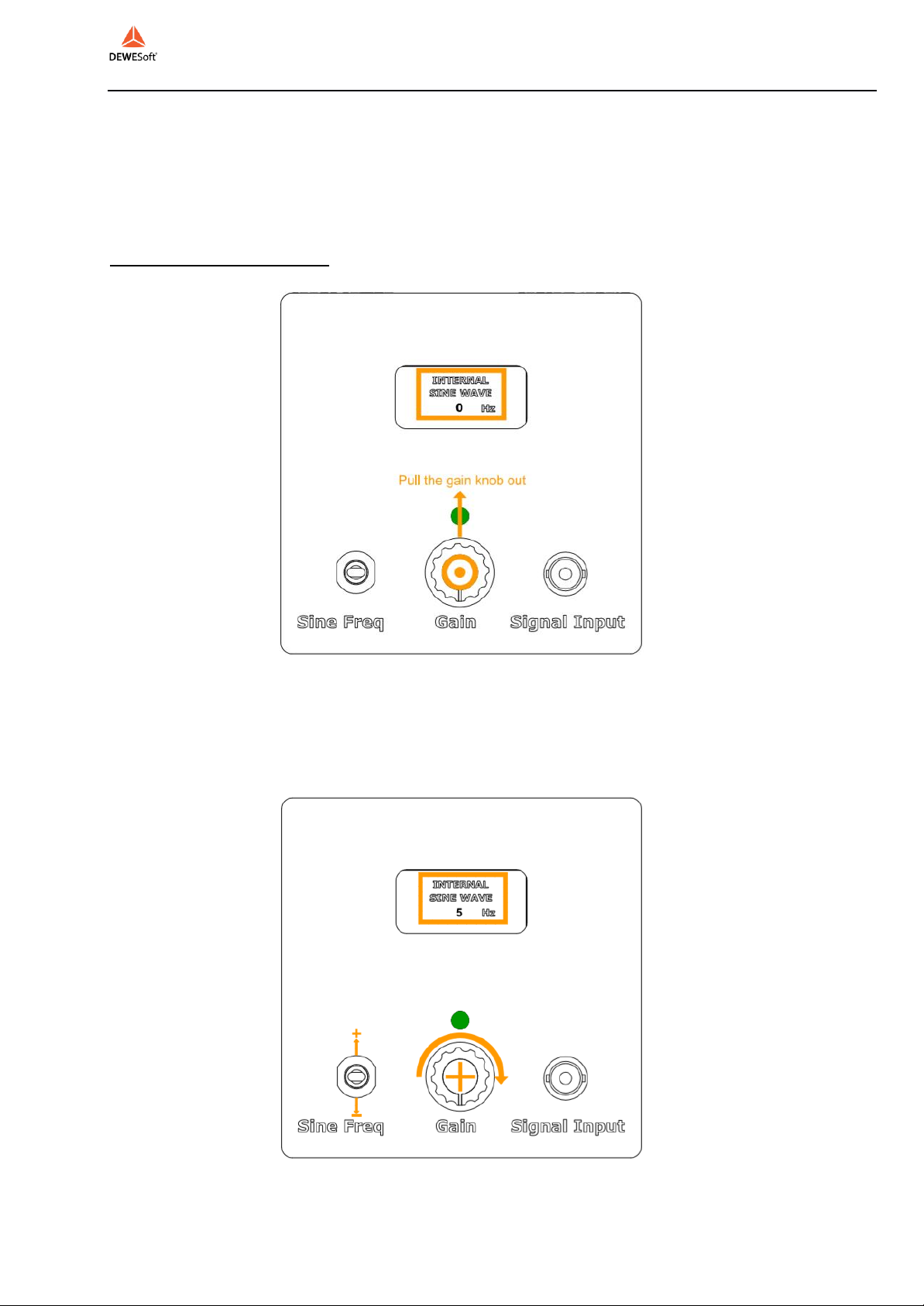
3.1.1-) External Signal Mode: ..........................................................................................................8
3.1.2-) Internal Signal Mode: ...........................................................................................................9
3.2) Power Requirements ...................................................................................................................10
3.3) Cooling........................................................................................................................................10
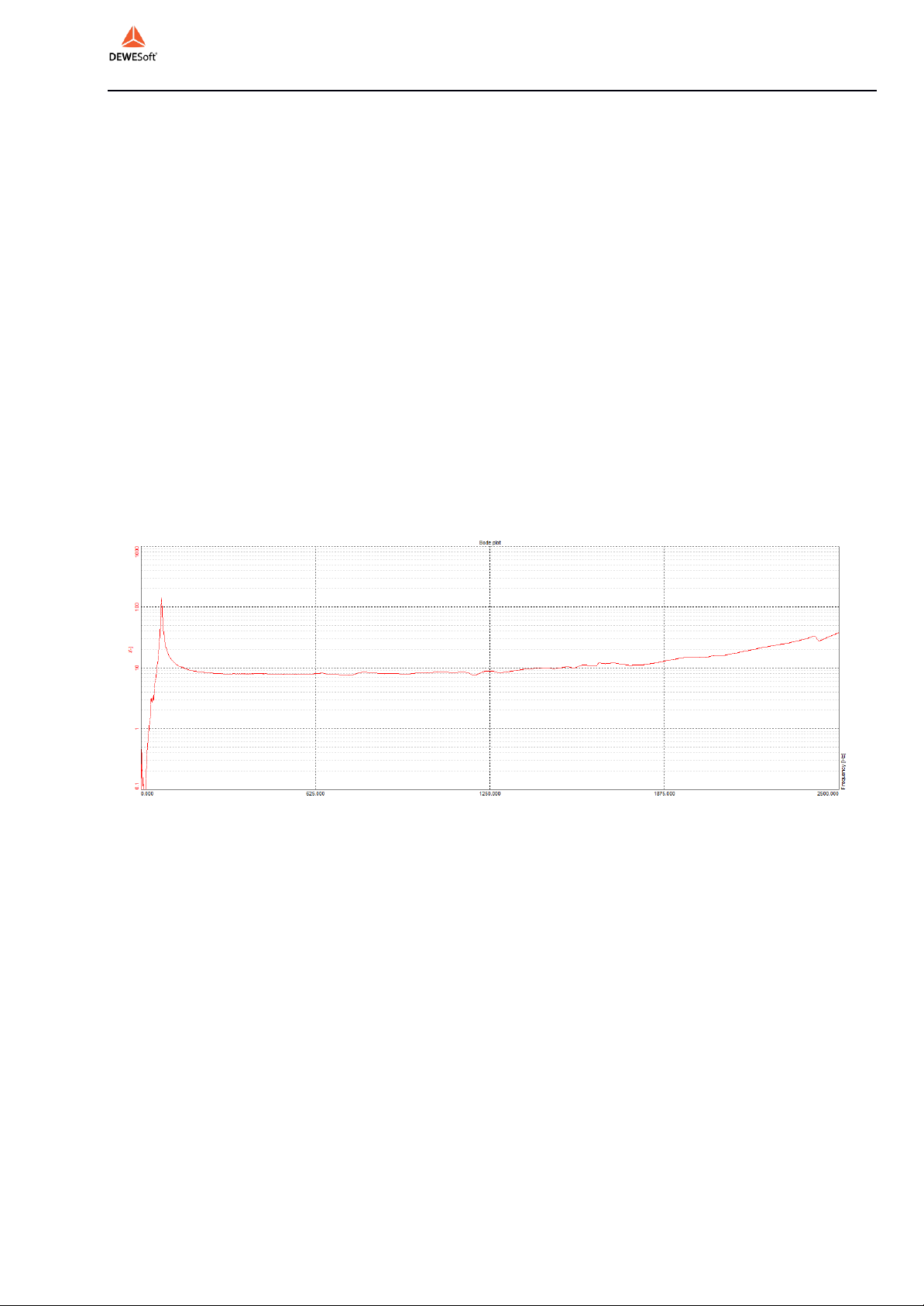
3.4) Frequency Response ...................................................................................................................10
3.5) Force Transducer Mounting........................................................................................................11
4) Maintenance and Troubleshooting.....................................................................................................14
5) Safety .................................................................................................................................................14

All rights reserved. Reproduction or issue to third parties in any form whatsoever is not permitted without written authority from the proprietors.
4
1) Introduction
The inertial shaker (DS-IS-5) is used for small structures requiring excitation
in low frequency bands. The shaker is directly connected to the structure and
the inertia motion of the shaker mass provides the necessary forces to the
structure. The shaker has a small, lightweight design that provides high
mobility. For this reason, it is suitable for use as a portable shaker.
2) General Information
2.1) Unpacking and Inspection
Dewesoft products provide adequate protection for undamaged products to be
transported. Document the damages that occur indirectly during the transport
and contact the customer representative. Check all components of the shaker.
If there is a defect, please contact us.
2.2) System Components
DS
-IS-5 has the following components:
-Electrodynamic Shaker
-Amplifier (DS-SA-150)
-Power Adapter
-Signal Cable
-Wrench
-User Manual
2.3) Theory of Operation
DS-IS-5 is an electromagnetic actuator. Electromagnetic actuators are
basically a voice coil consisting of magnet and coil. The moving element can
be a coil or magnet depending on the design requirements. The moving
element is usually suspended by an elastic spring. DS-IS-5 has a stationary
coil (drive coil) whose current is controlled to produce vibration. The
stationary magnetic field is produced by a magnet.

All rights reserved. Reproduction or issue to third parties in any form whatsoever is not permitted without written authority from the proprietors.
5
Item
Description
1
Shaker Head
2
Shaker Body
3
Signal Output
4
DC Power Input
5
Sine Freq
6
Gain Knob
7
External Signal Input
8
LCD Display

All rights reserved. Reproduction or issue to third parties in any form whatsoever is not permitted without written authority from the proprietors.
6
2.4) Specifications
Parameters
Specifications
Excitation Type
Vertical or Horizontal
Output Force (Sinus)
5 N
Frequency
10-1000 Hz
Displacement (Peak to Peak)
0.5 mm
Moving Mass
0.05 kg
Shaker Weight
0.06 kg
Suspension
Spring
Cooling System
Natural Convection
Operating Temperature Range
5-35 °C
Maximum Input Current
1A (RMS)
AMPLIFIER
EXTERNAL
Amplifier Weight
0.65 kg
Power Supply Voltage
19V DC
Power Supply Current
4.74 A
External Signal Voltage Level
1 VAC(PEAK)

All rights reserved. Reproduction or issue to third parties in any form whatsoever is not permitted without written authority from the proprietors.
7
2.5) Outline Drawing
The dimensional properties of DS-IS-5 shakers are given below. All
dimensions are in mm’s.

All rights reserved. Reproduction or issue to third parties in any form whatsoever is not permitted without written authority from the proprietors.
8
3) Operation and Installation
3.1) General
The general shaker connector configuration is given below.
The Gain Knob is a push-pull and rotational switch. The amplifier is in
External Signal Mode when the Gain Knob is pushed in and the amplifier is
in Internal Signal Mode when it is pulled out.
In order to protect the amplifier from electrical problems, it is advised to turn
the Gain Knob counter clockwise to the lowest gain position before
connecting the external signal cable or before changing operational modes.
3.1.1-) External Signal Mode:
Connect DC power source and drive signal to shaker power input and signal
input respectively. Start the external signal source. Adjust the Gain of the
amplifier by turning the Gain Knob clockwise.

All rights reserved. Reproduction or issue to third parties in any form whatsoever is not permitted without written authority from the proprietors.
9
3.1.2-) Internal Signal Mode:
The amplifier can generate sine signal from 1Hz to 15kHz with 1 Hz
increments that the user can adjust with the Sine Frequency Generator
Switch. Connect DC power source and drive signal to shaker power input.
Pull the Gain Knob out.
Raise or lower the Sine Frequency Generator Switch to the desired Sine
frequency. Adjust the Gain of the amplifier by turning the Gain Knob
clockwise. The frequency of the generated sine signal will be visible on the
LCD Screen.

All rights reserved. Reproduction or issue to third parties in any form whatsoever is not permitted without written authority from the proprietors.
10
3.2) Power Requirements
DS-IS-5 has an external power amplifier which is powered by its power
adaptor. Please note the output voltage and current ratings of the adaptor if
a replacement adaptor is to be used.
3.3) Cooling
DS-IS-5 does not require forced cooling. Air convection cooling is sufficient
for the force levels given in the specifications.
3.4) Frequency Response
The DS-IS-5 has a relatively flat force response of 5N after 140Hz and can
achieve 5N at approximately 50 Hz. The following figure shows the Force
(Newton) over applied Voltage (Volt) frequency response of DS-IS-5.
FOR FIXED FREQUENCY SINE TESTING, APPLICATION OF VOLTAGE
LEVELS ABOVE 0.5V FOR LONG DURATIONS (>1MIN) CAN
PERMANENTLY DAMAGE THE SHAKER.
THE SHAKER SUSPENSION NATURAL FREQUENCY IS ABOUT 74 HZ.
ESPECIALLY FOR FIXED FREQUENCY SINE TESTING, THE USER
SHOULD ALWAYS LOWER THE GAIN FOR THE FREQUENCY BAND OF 50-
170 HZ. OTHERWISE, DUE TO THE HIGH RESPONSE OF THE SHAKER
AROUND ITS RESONANCE FREQUENCY, VERY HIGH AMPLITUDES OF
VIBRATION (⁓70N) WILL OCCUR AND PERMANENTLY DAMAGE THE
SHAKER.
THE INTERNAL SINE SIGNAL GENERATOR SUPPLIES A CONSTANT
VOLTAGE OF 0.3VAC. PLEASE LOWER THE GAIN IN THE VICINITY OF
THE NATURAL FREQUENCY AS HIGHLIGHTED ABOVE.
N/V

All rights reserved. Reproduction or issue to third parties in any form whatsoever is not permitted without written authority from the proprietors.
11
3.5) Force Transducer Mounting
The DS-IS-5 has a 10-32 UNF screw interface for force transducer
mounting. Simply remove the Shaker Head by turning it counter clockwise
and mount the force transducer. In order to tighten the force transducer
properly, hold the flange of the screw with the supplied wrench or any other
tool available as shown.

All rights reserved. Reproduction or issue to third parties in any form whatsoever is not permitted without written authority from the proprietors.
12
NEVER APPLY FORCE ON THE SHAKER BODY TO REMOVE THE
SHAKER FROM THE MOUNTING SURFACE!

All rights reserved. Reproduction or issue to third parties in any form whatsoever is not permitted without written authority from the proprietors.
13
ALWAYS USE A WRENCH AT THE FORCE TRANSDUCER TO
REMOVE THE SHAKER FROM THE MOUNTING SURFACE!

All rights reserved. Reproduction or issue to third parties in any form whatsoever is not permitted without written authority from the proprietors.
14
4) Maintenance and Troubleshooting
The DS-IS-5 shaker is a sealed device requiring no maintenance if the
operating instructions described in this manual are followed. Repair of the
coil, exciter body or magnet core should not be attempted. Please return the
shaker to Dewesoft for proper repair.
Do not apply high levels of axial force on the shaker. The suspension spring
is designed to carry the shaker weight only.
Inadequate mounting of force transducers or shaker head can lead to
permanent damage to the shaker. If such a case happens please send the
shaker to Dewesoft for repair.
5) Safety
Please ensure that this manual section is reviewed and understood prior to
installation, operation or maintenance of the equipment. The danger of
electrical shock or fire always exists in electrical equipment. The DS-IS-5
Inertial Shaker is designed for safe operation. Safety features such as
electrical insulation on outer surfaces, shaker body grounding connection
are provided for safe operation of the shaker system. Always monitor the
applied voltage to the amplifier and shut down the shaker if the temperature
of the shaker body rises drastically or smoke is observed from the shaker
due to high voltage levels applied.
Table of contents
Other DEWESOFT Paint Sprayer manuals