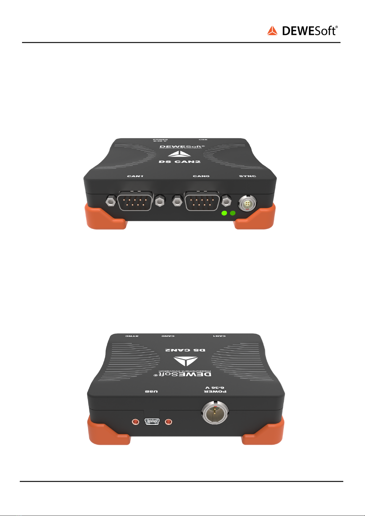
DEWESOFT DS-CAN2 Product manual

DS-CAN2
TECHNICAL REFERENCE MANUAL
DS-CAN2 V20-2
1

DS-CAN2
TECHNICAL REFERENCE MANUAL
1. Table of contents
1. Table of contents 2
2. About this document 3
2.1. Legend 3
3. Specifications 4
4. Device operation 5
4.1. Front and back side 5
4.2. Connectors 6
4.2.1: CAN connector 6
4.2.2. Power connector 6
4.2.3. Sync connector 7
5. Using DS-CAN2 in DewesoftX® 7
5.1. Hardware setup 7
5.1.1. Start up of the device 7
5.2. Losing USB connection 8
6. Firmware upgrade 9
7. DewesoftX® license information 9
8. Warranty information 11
8.1. Calibration 11
8.2. Support 11
8.3. Service/repair 11
8.4. Restricted Rights 11
8.5. Printing History 12
8.6. Copyright 12
8.7. Trademarks 12
9. Safety instructions 13
9.1. Safety symbols in the manual 13
9.2. General Safety Instructions 13
10.2.1. Environmental Considerations 13
10.2.2. Product End-of-Life Handling 13
10.2.3. System and Components Recycling 13
10.2.4. General safety and hazard warnings for all Dewesoft systems 14
11. Documentation version history 17
DS-CAN2 V20-2 2/17

DS-CAN2
TECHNICAL REFERENCE MANUAL
2. About this document
2.1. Legend
The following symbols and formats will be used throughout the document.
Important
It gives you important information about the subject.
Please read carefully!
Hint
It gives you a hint or provides additional information about a subject.
Example
Gives you an example of a specific subject.
DS-CAN2 V20-2 3/17

DS-CAN2
TECHNICAL REFERENCE MANUAL
3. Specifications
DS-CAN2 V20-2 4/17
DS-CAN2
SIRIUSim-4xCAN
SIRIUSi-8xCAN
SIRIUSif-8xCAN
SIRIUSiw-8xCAN
CAN specification
Number of ports
2
4
8 + 1
8 + 1
8 + 1
Interface type
CAN 2.0B
CAN 2.0B
CAN 2.0B
CAN 2.0B
CAN 2.0B
Interface data rate
up to 1 Mbit/sec
up to 1 Mbit/sec
up to 1 Mbit/sec
up to 1 Mbit/sec
up to 1 Mbit/sec
Special protocols
OBDII, J1939, CAN
out
OBDII, J1939, CAN out
OBDII, J1939, CAN
out
OBDII, J1939,
CAN out
OBDII, J1939, CAN
out
Sampling rate
> 10 kHz per channel
Software selectable
> 10 kHz per channel
Software selectable
> 10 kHz per channel
Software selectable
> 10 kHz per
channel
Software
selectable
> 10 kHz per
channel
Software
selectable
Galvanic isolation
(Sensor supply not
isolated)
Isolated
Isolated
Isolated
Isolated
Isolated
Bus pin fault
protection
±36 V
±36 V
±36 V
±36 V
±36 V
Power specification
Power supply
6 - 36 V DC
Startup voltage 7V
Max voltage 5.00 ±0.25 V
2x USB 2.0 powered
9 - 36 V DC
9 - 36 V DC
9 - 36 V DC
Maximum sensor
power
consumption
3 W max total
(max 2W on 15V)
2.5 W max
1 W per channel
1 W per channel
Maximum power
consumption
5.5 W
5 W
Combined device & sensor
consumption
6.5 W (instrument) +
8 W (sensor)
6.5 W
(instrument) + 8
W (sensor)
Environmental specification
Interface
USB 2.0
USB 2.0
USB 2.0
USB 2.0
USB 2.0
Connector type
9 pin D-SUB
9 pin D-SUB
9 pin D-SUB
9 pin D-SUB
9 pin D-SUB
Physical
dimensions
105 x 90 x 30 mm
3.94 x 3.54 x 1.18 inch
145 x 139 x 64mm
5.71 x 5.43 x 2.52 inch
266x139x64mm
10.47 x 5.43 x 2.52
inch
266x139x64mm
10.47 x 5.43 x 2.52
inch
282 x 135 x 70 mm
11.10 x 5.47 x 2.76
inch
Weight
Weight 230 g
0.51 lbs
Weight 800 g
1.76 lbs
1320 g
2.90 lbs
1320 g
2.90 lbs
1930 g
4.25 lbs
Operating
temperature
-20°C to +60°C
-10°C to +50°C
-10°C to +50°C
-10°C to +50°C
-40°C to +60°C
Storage
temperature
-40°C to +70°C
-40°C to +70°C
-40°C to
+70°C
-40°C to
+70°C
-40°C to
+70°C
Humidity
95% RH non
condensing @ 60°C
95% RH non condensing
@ 60°C
95% RH non
condensing @ 60°C
95% RH non
condensing @
60°C
IP protection
-
-
-
IP50
IP65 / IP67

DS-CAN2
TECHNICAL REFERENCE MANUAL
4. Device operation
4.1. Front and back side
Front connectors:
Image 1: Front connectors
Back connectors:
Image 2: Back connectors
DS-CAN2 V20-2 5/17

DS-CAN2
TECHNICAL REFERENCE MANUAL
4.2. Connectors
4.2.1: CAN connector
9-pin D-SUB male connector for CAN bus:
4.2.2. Power connector
2-pin LEMO connector (mating cable connector: FGJ.1B.302CLLD42Z)
DS-CAN2 V20-2 6/17
CAN connector: pin-out (DSUB-9 male)
Pin
Name
Description
1
+5V
5 V supply
max. current: 500 mA
2
CAN_LOW
CAN low
3
DGND
Digital Ground
4
RES
Reserved
5
RES
Reserved
6
DGND
Digital Ground
7
CAN_HIGH
CAN high
8
RES
Reserved
9
+12V
12 V supply
max. current: 200 mA
Power out connector: pin-out (2-pin LEMO female)
Pin
Name
Description
1
V+
Supply
2
V-
Ground

DS-CAN2
TECHNICAL REFERENCE MANUAL
4.2.3. Sync connector
4-pin LEMO connector (mating cable connector: FGG.00.304CLAD27Z)
5. Using DS-CAN2 in DewesoftX®
5.1. Hardware setup
5.1.1. Start up of the device
Please connect the device via USB to PC. Note that power supply is not needed unless you want to
power external devices from DS-CAN2 (like CPAD2 module). Then make sure that the device is
connected to the PC when starting up DewesoftX®.
The device will be automatically recognized and shown in the Device settings.
Image 3: DS-CAN in device settings
DS-CAN2 V20-2 7/17
Sync connector: pin-out (4-pin LEMO female)
Pin
Name
Description
1
CLK
Clock
2
Trigg
Trigger
3
GPS-PPS
GPS - PPS
4
DGND
Digital Ground

DS-CAN2
TECHNICAL REFERENCE MANUAL
You will see the device information such as serial number, HW number and FW number on the right
site of the Settings window.
The two CAN ports are shown under the CAN section. By pressing on the Tool button you can adjust the
CAN port settings:
●Default baud rate
●Operation mode
●CAN plugin
Image 4: Adjusting CAN settings
5.2. Losing USB connection
When acquiring data and the USB connection is lost, the acquisition will stop. In this case reconnect the
unit and restart the acquisition with the reconnect button.
In this case (if the data was being stored, the gap will be filled in with missing data).
Image 5: Gaps in the data file, due to disconnection of the device
DS-CAN2 V20-2 8/17

DS-CAN2
TECHNICAL REFERENCE MANUAL
6. Firmware upgrade
●Download the Dewesoft upgrade package (.dxu file) from the Dewesoft downloads page under
the section Drivers.
●Unzip the file and copy the *.dxu file into the Firmwares folder of your DewesoftX® installation
(e.g. D:\DewesoftX\System\\Firmwares).
●Connect the Dewesoft instrument to the PC and run DewesoftX®
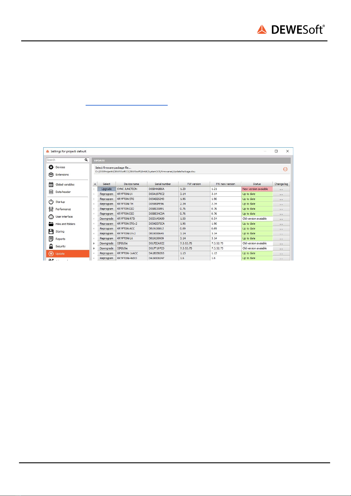
●Go to settings under the Update tab:
Image 6: Update options
●If the firmware package isn’t selected, select it by pressing the button and find the folder with
the firmware file in it.
●Select the device you want to upgrade and start the firmware upgrade by pressing the
“Upgrade” button.
7. DewesoftX® license information
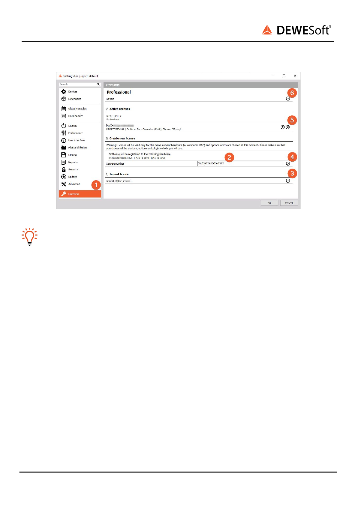
DS-CAN2 or any other Dewesoft device already comes with an embedded Dewesoft license. You can
check the license details with all the available options in the Licensing tab ❶by pressing the three
dotted buttons ❻. However if the user decides to upgrade the license with an additional extension,
DewesoftX® will require a new license registration. The registration can be made online ❷or offline by
importing an offline license ❸in case the system doesn’t have an internet connection. Offline license
can be pre-registered on a different PC with the internet connection. If needed, the license can also be
written on the actual device ❺.
Active and embedded licenses are seen under the Active licenses tab. If the license is recognized as
none active, it usually means that the wrong license was entered.
DS-CAN2 V20-2 9/17

DS-CAN2
TECHNICAL REFERENCE MANUAL
Image 7: Licensing options
Hint
All licenses regarding Krypton will only work when the Krypton system is connected to your PC
and the device has been activated in the hardware setup.
DS-CAN2 V20-2 10/17

DS-CAN2
TECHNICAL REFERENCE MANUAL
8. Warranty information
Notice
The information contained in this document is subject to change without notice.
Note:
Dewesoft d.o.o. shall not be liable for any errors contained in this document. Dewesoft MAKES NO
WARRANTIES OF ANY KIND WITH REGARD TO THIS DOCUMENT, WHETHER EXPRESS OR IMPLIED.
DEWESOFT SPECIFICALLY DISCLAIMS THE IMPLIED WARRANTIES OF MERCHANTABILITY AND
FITNESS FOR A PARTICULAR PURPOSE. Dewesoft shall not be liable for any direct, indirect, special,
incidental, or consequential damages, whether based on contract, tort, or any other legal theory, in
connection with the furnishing of this document or the use of the information in this document.
The copy of the specific warranty terms applicable to your Dewesoft product and replacement parts can
be obtained from your local sales and service office. To find a local dealer for your country, please visit
https://dewesoft.com/support/distributors.
8.1. Calibration
Every instrument needs to be calibrated at regular intervals. The standard norm across nearly every
industry is annual calibration. Before your Dewesoft data acquisition system is delivered, it is calibrated.
Detailed calibration reports for your Dewesoft system can be requested. We retain them for at least one
year, after system delivery.
8.2. Support
Dewesoft has a team of people ready to assist you if you have any questions or any technical difficulties
regarding the system. For any support please contact your local distributor first or Dewesoft directly.
Dewesoft d.o.o.
Gabrsko 11a
1420 Trbovlje Slovenia
Europe Tel.: +386 356 25 300
Web: http://www.dewesoft.com
The telephone hotline is available Monday to Friday from 07:00 to 16:00 CET (GMT +1:00)
8.3. Service/repair
The team of Dewesoft also performs any kinds of repairs to your system to assure a safe and proper
operation in the future. For information regarding service and repairs please contact your local
distributor first or Dewesoft directly on https://dewesoft.com/support/rma-service.
8.4. Restricted Rights
Use Slovenian law for duplication or disclosure. Dewesoft d.o.o. Gabrsko 11a, 1420 Trbovlje, Slovenia /
Europe.
DS-CAN2 V20-2 11/17

DS-CAN2
TECHNICAL REFERENCE MANUAL
8.5. Printing History
Version 2.0.0, Revision 217 Released 2015 Last changed: 23. July 2018 at 16:54.
8.6. Copyright
Copyright © 2015-2019 Dewesoft d.o.o. This document contains information which is protected by
copyright. All rights are reserved. Reproduction, adaptation, or translation without prior written
permission is prohibited, except as allowed under the copyright laws. All trademarks and registered
trademarks are acknowledged to be the property of their owners.
8.7. Trademarks
We take pride in our products and we take care that all key products and technologies are registered as
trademarks all over the world. The Dewesoft name is a registered trademark. Product families
(KRYPTON, SIRIUS, DSI, DS-NET) and technologies (DualCoreADC, SuperCounter, GrandView) are
registered trademarks as well. When used as the logo or as part of any graphic material, the registered
trademark sign is used as a part of the logo. When used in text representing the company, product or
technology name, the ® sign is not used. The Dewesoft triangle logo is a registered trademark but the ®
sign is not used in the visual representation of the triangle logo.
DS-CAN2 V20-2 12/17

DS-CAN2
TECHNICAL REFERENCE MANUAL
9. Safety instructions
Your safety is our primary concern! Please be safe!
9.1. Safety symbols in the manual
Warning
Calls attention to a procedure, practice, or condition that could cause the body injury or death
Caution
Calls attention to a procedure, practice, or condition that could possibly cause damage to
equipment or permanent loss of data.
9.2. General Safety Instructions
Warning
The following general safety precautions must be observed during all phases of operation, service, and
repair of this product. Failure to comply with these precautions or with specific warnings elsewhere in
this manual violates safety standards of design, manufacture, and intended use of the product.
Dewesoft GmbH assumes no liability for the customer’s failure to comply with these requirements.
All accessories shown in this document are available as an option and will not be shipped as standard
parts.
10.2.1. Environmental Considerations
Information about the environmental impact of the product.
10.2.2. Product End-of-Life Handling
Observe the following guidelines when recycling a Dewesoft system:
10.2.3. System and Components Recycling
Production of these components required the extraction and use of natural resources. The substances
contained in the system could be harmful to your health and to the environment if the system is
improperly handled at its end of life! Please recycle this product in an appropriate way to avoid
unnecessary pollution of the environment and to keep natural resources.
This symbol indicates that this system complies with the European Union’s requirements
according to Directive 2002/96/EC on waste electrical and electronic equipment (WEEE).
Please find further information about recycling on the Dewesoft web site
www.dewesoft.com
DS-CAN2 V20-2 13/17

DS-CAN2
TECHNICAL REFERENCE MANUAL
Restriction of Hazardous Substances
This product has been classified as Monitoring and Control equipment and is outside the scope of the
2002/95/EC RoHS Directive. However, we take care of our environment and the product is lead-free.
10.2.4. General safety and hazard warnings for all Dewesoft systems
Safety of the operator and the unit depend on following these rules.
●Use this system under the terms of the specifications only to avoid any possible danger.
●Read your manual before operating the system.
●Observe local laws when using the instrument.
●DO NOT touch internal wiring!
●DO NOT use higher supply voltage than specified!
●Use only original plugs and cables for harnessing.
●You may not connect higher voltages than rated to any connectors.
●The power cable and connector serve as Power-Breaker. The cable must not exceed 3 meters,
the disconnect function must be possible without tools.
●Maintenance must be executed by qualified staff only.
●During the use of the system, it might be possible to access other parts of a more comprehensive
system. Please read and follow the safety instructions provided in the manuals of all other
components regarding warning and security advice for using the system.
●With this product, only use the power cable delivered or defined for the host country.
●DO NOT connect or disconnect sensors, probes or test leads, as these parts are connected to a
voltage supply unit.
●Ground the equipment: For Safety Class 1 equipment (equipment having a protective earth
terminal), a non-interruptible safety earth ground must be provided from the main power source
to the product input wiring terminals.
●Please note the characteristics and indicators on the system to avoid fire or electric shocks.
Before connecting the system, please read the corresponding specifications in the product
manual carefully.
●The inputs must not, unless otherwise noted (CATx identification), be connected to the main
circuit of category II, III and IV.
●The power cord separates the system from the power supply. Do not block the power cord, since
it has to be accessible for the users.
●DO NOT use the system if equipment covers or shields are removed.
●If you assume the system is damaged, get it examined by authorized personnel only.
●Adverse environmental conditions are Moisture or high humidity Dust, flammable gases, fumes
or dissolver Thunderstorm or thunderstorm conditions (except assembly PNA) Electrostatic
fields, etc.
●The measurement category can be adjusted depending on module configuration.
●Any other use than described above may damage your system and is attended with dangers like
short-circuiting, fire or electric shocks.
●The whole system must not be changed, rebuilt or opened.
●DO NOT operate damaged equipment: Whenever it is possible that the safety protection
features built into this product have been impaired, either through physical damage, excessive
moisture, or any other reason, REMOVE POWER and do not use the product until the safe
operation can be verified by service-trained personnel. If necessary, return the product to
Dewesoft sales and service office for service and repair to ensure that safety features are
maintained.
DS-CAN2 V20-2 14/17

DS-CAN2
TECHNICAL REFERENCE MANUAL
●If you assume a more riskless use is not provided anymore, the system has to be rendered
inoperative and should be protected against inadvertent operation. It is assumed that a more
riskless operation is not possible anymore if the system is damaged obviously or causes strange
noises. the system does not work anymore. The system has been exposed to long storage in
adverse environments. the system has been exposed to heavy shipment strain.
●Warranty void if damages caused by disregarding this manual. For consequential damages, NO
liability will be assumed!
●Warranty void if damage to property or persons caused by improper use or disregarding the
safety instructions.
●Unauthorized changing or rebuilding the system is prohibited due to safety and permission
reasons (CE).
●Be careful with voltages >25 VAC or >35 VDC! These voltages are already high enough in order to
get a perilous electric shock by touching the wiring.
●The product heats during operation. Make sure there is adequate ventilation. Ventilation slots
must not be covered!
●Only fuses of the specified type and nominal current may be used. The use of patched fuses is
prohibited.
●Prevent using metal bare wires! Risk of short circuit and fire hazard!
●DO NOT use the system before, during or shortly after a thunderstorm (risk of lightning and high
energy over-voltage). An advanced range of application under certain conditions is allowed with
therefore designed products only. For details please refer to the specifications.
●Make sure that your hands, shoes, clothes, the floor, the system or measuring leads, integrated
circuits and so on, are dry.
●DO NOT use the system in rooms with flammable gases, fumes or dust or in adverse
environmental conditions.
●Avoid operation in the immediate vicinity of high magnetic or electromagnetic fields,
transmitting antennas or high-frequency generators, for exact values please refer to enclosed
specifications.
●Use measurement leads or measurement accessories aligned with the specification of the
system only. Fire hazard in case of overload!
●Do not switch on the system after transporting it from a cold room to a warm room and vice
versa. The thereby created condensation may damage your system. Acclimatise the system
unpowered to room temperature.
●Do not disassemble the system! There is a high risk of getting a perilous electric shock.
Capacitors still might be charged, even if the system has been removed from the power supply.
●The electrical installations and equipment in industrial facilities must be observed by the security
regulations and insurance institutions.
●The use of the measuring system in schools and other training facilities must be observed by
skilled personnel.
●The measuring systems are not designed for use in humans and animals.
●Please contact a professional if you have doubts about the method of operation, safety or the
connection of the system.
●Please be careful with the product. Shocks, hits and dropping it from already- lower level may
damage your system.
●Please also consider the detailed technical reference manual as well as the security advice of the
connected systems.
●This product has left the factory in safety-related flawlessness and in proper condition. In order to
maintain this condition and guarantee safety use, the user has to consider the security advice
and warnings in this manual.
DS-CAN2 V20-2 15/17

DS-CAN2
TECHNICAL REFERENCE MANUAL
EN 61326-3-1:2008
IEC 61326-1 applies to this part of IEC 61326 but is limited to systems and equipment for industrial
applications intended to perform safety functions as defined in IEC 61508 with SIL 1-3.
The electromagnetic environments encompassed by this product family standard are industrial, both
indoor and outdoor, as described for industrial locations in IEC 61000-6-2 or defined in 3.7 of IEC 61326-1.
Equipment and systems intended for use in other electromagnetic environments, for example, in the
process industry or in environments with potentially explosive atmospheres, are excluded from the
scope of this product family standard, IEC 61326-3-1.
Devices and systems according to IEC 61508 or IEC 61511 which are considered as “operationally
well-tried”, are excluded from the scope of IEC 61326-3-1.
Fire-alarm and safety-alarm systems, intended for the protection of buildings, are excluded from the
scope of IEC 61326-3-1.
DS-CAN2 V20-2 16/17

DS-CAN2
TECHNICAL REFERENCE MANUAL
11. Documentation version history
DS-CAN2 V20-2 17/17
Version
Date
Notes
V20-2
12.10.2020
Small cosmetic updates
V20-1
31.8.2020
New Template
Table of contents
Popular Recording Equipment manuals by other brands

Axxess
Axxess AXDSPX-BM1 installation instructions

auray
auray iso-armor owner's manual

SMC Networks
SMC Networks EX180-SDN4 Series Installation & maintenance manual

TC Electronic
TC Electronic Multi-effects Processor G-Natural user manual

Symetrix
Symetrix SX208 user manual

ETC
ETC Echo Integration Interface installation guide