DF ROBOT URM37V4.0 User manual
URM37V4.0UltrasonicSensor(SKU:SEN0001)
URM37 V4.0 Ultrasonic Sensor
Contents
1Introduction
2Specification
3PinOut
4Tutorial
4.1 Button for RS232/TTL Choosing
4.2 Test on Software
4.3 Othere Setting address in EEPROM
4.4 The factory default settings
4.5 Three Measure Modes
4.5.1 PWM trigger mode
4.5.2 Auto Measure Mode
4.5.3 Serial Passive Mode
4.6 Servo Rotation Reference Table
5Protocol
6Trouble shooting
7More
Introduction
URM37 V4.0 Ultrasonic Sensor uses an industrial level AVR processor as the main processing unit.
It comes with a temperature correction which is very unique in its class. URM37 V3.2 (last version)
has already been a very good realization of ultrasonic switch and serial (TTL and RS232 level
optional), pulse output function, the module can also control a servo rotation to realize a spatial
ultrasound scanner. On this basis we have to upgrade the function. URM37 V4.0, the current version

has better intelligence capabilities, meanwhile, mechanical dimensions and pin interface and
communication commands are compatible with V3.2, V3.2 has been reversed based on the following
changes:
Serial level selected from the skipped stitches to button, user can easily select RS232 or TTL-level
output level output by pressing the settings( after reboot ).
Modified the algorithm, so dead zone was reduced and enhance accuracy.
Analog voltage output, voltage and the measured distance is proportional.
Wide voltage support +3.3V-5.0V.
Power reverse protection.
Automatic measurement of time interval can be modified.
Modify a servo controlled angle of 0-180, compatible with the most of the servos on the market.
Measuring time is 100ms.
Specification
Power: +3.3V~+5.0V
Current: <20mA
Working temperature: -10~+70
Detecting range: 5cm-500cm
Resolution: 1cm
Interface: RS232 (TTL), PWM
Size: 22mm × 51 mm
Weight: 25g
PinOut

Tutorial
Congratulations to you who bought our URM37 V4.0 Ultrasonic Sensor3, you now have the historical
most powerful ultrasonic ranging module.
First we have to understand this module basic function, there are three modes:
1. PWM triggered measurement mode
2. Automatically measure mode
3. Serial passive measurement
Then it also supports:
Simulation volume output (proportional with measurement distance, 6.8mV/cm )
Temperature read
Serial level choose(TTL or RS232 level)
Internal EEPROM without losing data
Serial EEPROM data read
The products have been conducted a set of rigorous tests by us, when you get your purchase, you
can do some setting according to your demands, firstly, you may have to set the serial port-level (or
RS232 TTL level), then we can access to the module through the serial port, then set the range
mode (0x02 writes data on the internal EEPROM address), after that, you can access to ultrasound
module through MCU or PC.
To begin with this Ultrasonic Sensor, there is a software could help to make it a lot of easier. And
there are some paramenters you may want to reverse to meet more situations.
NumLabel Description
1 VCC Power input (reference +5V)
2 GND Ground
3 NRST Reset
4 ECHO Measured distance presented by the Data Output 0-25000US by PWM pulse
width, 1 CM / 50US representative
5 MOTO Control the servo rotation angle
6 COMP/TRIG
COMP:On/OFF mode, when the detecting distance is smaller than a pre-set
value, this pin pulls low./TRIG:PWM mode trigger input
7 DAC
A
nalog voltage output ( each 6.8mV represents 1 cm )
8 RXD RS232/TTL mode
9 TXD RS232/TTL mode

ButtonforRS232/TTLChoosing
The vesy fisrt basic step to communicate with the model is to choose the serial level_TTL(default) or
RS232.We step forward over the last version3.2 which by jumper, now we could do it by pressing
the only one button on the board for 1 second, after the light turn off from state-on, release the
botton.Repower again,he Indicator appears to flash like once long and once short -present TTL
level output, once long and twice short flash presenting RS232 level.
Do not connect to TTL MCU when the output mode is set to RS232, doing so will permanently
damage the unit.
TestonSoftware
This feature is only available for Rev2 and after. If there are no jumpers, or no button on the back of
the sensor, the sensor should be Rev1 and hence not supporting this feature.

TTL Mode Connection Diagram
RS232 Mode Connection Diagram
Power on the sensor, read the blink of the LED(active) to get the serial level(see above), wire
according to the above picture.After this,you can use our "URMV3.2HelpMate" to test the module.
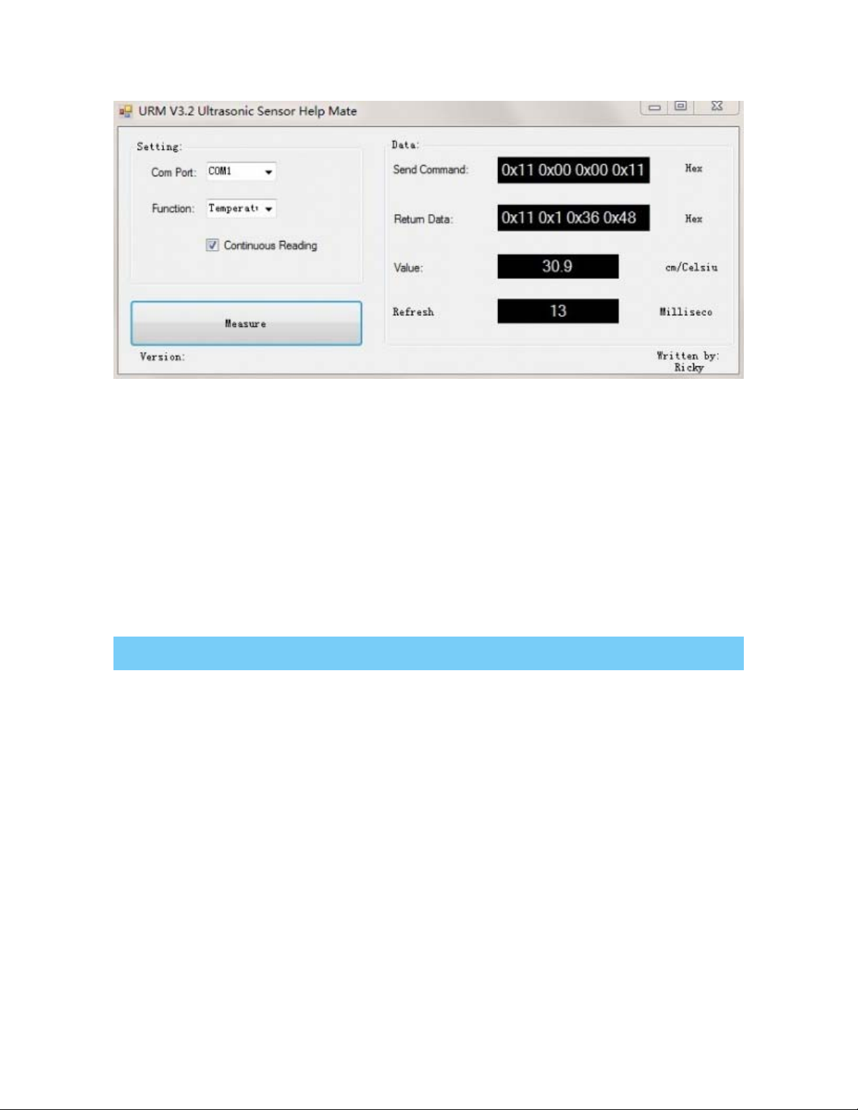
The usage of the software is very simple: ensure that there is no other software on the computer
occupied the serial port, and then run Mate.exe, select the COM Port, and choose the parameter
what you want to measure, and choose the "Continuous Reading ". Click "Measure" it will measure
the temperature and the distance.
OthereSettingaddressinEEPROM
Here, we are talking about the meaning of the data in EEPROM several addresses.(For more
details, can be found in the [Serial control protocol] part)
Address Meaning
0x00 larger than set distance
0x01 less than set distance
0x02 measure mode(write 0xaa present automatically measure mode, other data except
0xaa present PWM Passive measurement mode )
0x03 Serial level mode(TTL/RS232)(write 0x00 present TTL mode, 0x01 present RS232
mode, other data will be modified to 0x00)
0x04 automatically measure time span(default set is the lowest 25ms, witting format is 8-
bit 16 binary, e.g. Write 64 means 100ms)
Thefactorydefaultsettings
Serial TTL level
Measure mode: PWM trigger
Comparison of distance : 0
Automatically measure interval time:25ms
Internal EEPROM Data are all 0x00
the EEPROM address are unavailable: 0x00~0x04, please do not try to modify the data.
ThreeMeasureModes
PWM trigger mode
In PWM trigger mode, pin COMP/TRIG produces a low level of triggered pulse signal starting
distance measurement operation once.
Upload the code below to your arduino board, wire the devices together, then you can realize the
distance measurement.
URM37 V4.0 Ultrasonic Sensor
demo code

1
2 // # Editor : ZRH from DFRobot
3 // # Date : 29.08.2014
4
5 // # Product name: URM V4.0 ultrasonic sensor
6 // # Product SKU : SEN0001
7 // # Version : 1.0
8
9 // # Description:
10 // # The Sketch for scanning 180 degree area 3-500cm detecting range
11 // # The sketch for using the URM37 PWM trigger pin mode from DFRobot
12 // # and writes the values to the serialport
13 // # Connection:
14 // # Vcc (Arduino) -> Pin 1 VCC (URM V4.0)
15 // # GND (Arduino) -> Pin 2 GND (URM V4.0)
16 // # Pin 3 (Arduino) -> Pin 4 ECHO (URM V4.0)
17 // # Pin 5 (Arduino) -> Pin 6 COMP/TRIG (URM V4.0)
18 // # Pin A0 (Arduino) -> Pin 7 DAC (URM V4.0)
19 // # Working Mode: PWM trigger pin mode.
20
21 #define Measure 1 //Mode select
22 int URECHO = 3; // PWM Output 0-25000US,Every 50US represent 1cm
23 int URTRIG = 5; // PWM trigger pin
24 int sensorPin = A0; // select the input pin for the potentiometer
25 int sensorValue = 0; // variable to store the value coming from the sen
sor
26
27 unsigned int DistanceMeasured= 0;
28
29 void setup()
30 {
31 //Serial initialization
32 Serial.begin(9600); // Sets the baud rate to 9600

33 pinMode(URTRIG,OUTPUT); // A low pull on pin COMP/TRI
G
34 digitalWrite(URTRIG,HIGH); // Set to HIGH
35 pinMode(URECHO, INPUT); // Sending Enable PWM mode co
mmand
36 delay(500);
37 Serial.println("Init the sensor");
38
39 }
40 void loop()
41 {
42 PWM_Mode();
43 delay(100);
44 }
45
46 void PWM_Mode() // a low pull on pin COMP/TRI
G triggering a sensor reading
47 {
48 Serial.print("Distance Measured=");
49 digitalWrite(URTRIG, LOW);
50 digitalWrite(URTRIG, HIGH); // reading Pin PWM will output
pulses
51 if( Measure)
52 {
53 unsigned long LowLevelTime = pulseIn(URECHO, LOW) ;
54 if(LowLevelTime>=45000) // the reading is invalid.
55 {
56 Serial.print("Invalid");
57 }
58 else{
59 DistanceMeasured = LowLevelTime /50; // every 50us low level stands
for 1cm
60 Serial.print(DistanceMeasured);
61 Serial.println("cm");
62 }
63

64 }
65 else {
66 sensorValue = analogRead(sensorPin);
67 if(sensorValue<=10) // the reading is invalid.
68 {
69 Serial.print("Invalid");
70 }
71 else {
72 sensorValue = sensorValue*0.718;
73 Serial.print(sensorValue);
74 Serial.println("cm");
75 }
76 }
77 }
result
Open the IDE serial port, the distance is display on it.

URM37 V4.0 Ultrasonic Sensor
In the above code, you may not get the distance like 500cm, for we just set it like 450cm.This is just
a basic demo, after this, we will dive deeper to find more about it. Note: reverse the code”#define
Measure 1 ” to “#define Measure 0”, and it can read the distance by analog value.
NOTE: PWM trigger mode support multiple parallel modules.
Auto Measure Mode
By means of the computer software or MCU Module, write 0xAA to 0x02 address to switch to
automatic measurement mode. Writting a 8-bit 16 binary data to 0x04 address to reverse the
measure time interval.
This module measures distance automatically every 25 ms (Settable) , then compare the data with
the set value, if equal to or less than the set value, COMP/TRIG pin output low. In addition, in every
measure,the PWM Terminal will read the distance as a low level pulse, 50uS represents 1 cm.
Tips:if you have set the Compare value, you could use this module as a Ultrasonic Switch.

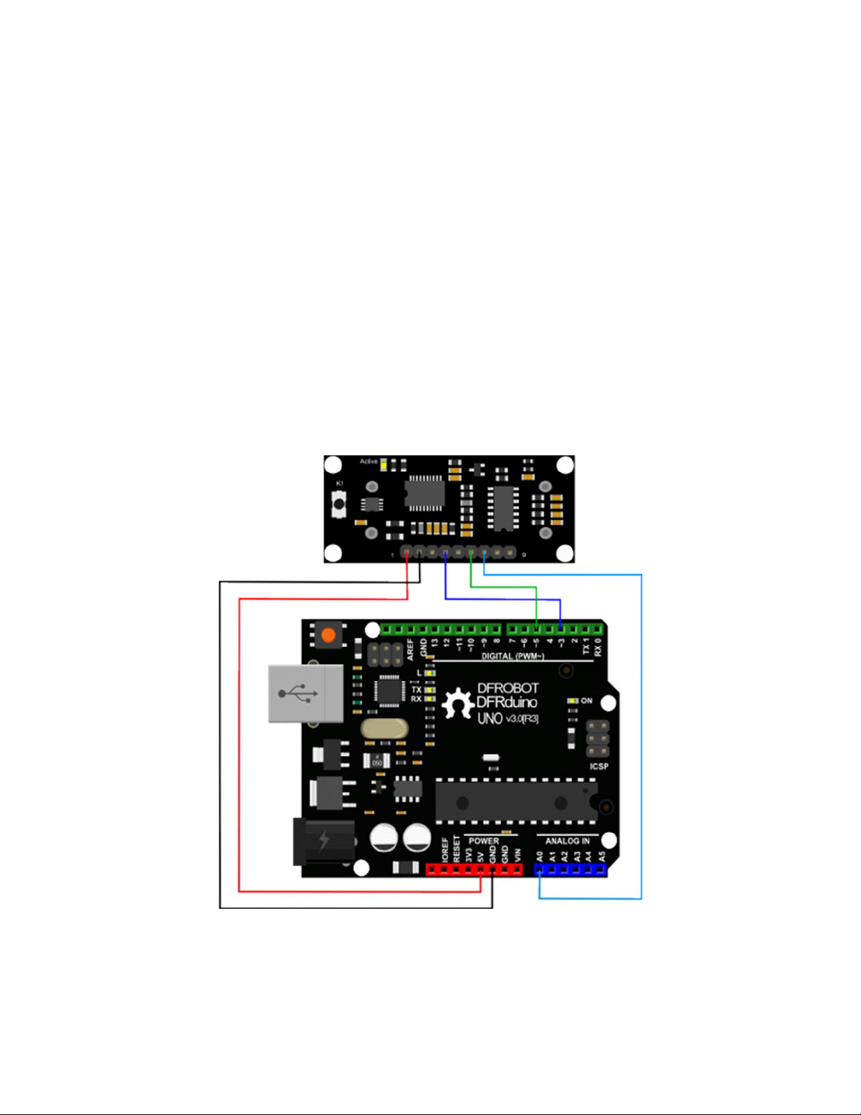
Download the sample code to the Arduino board, then wire as shown modules and Arduino
connected on ultrasonic distance measurement can be achieved.Note:download first before connect
the Arduino TX/RX, or download will failed.
Demo Code
1 //Put your code here
2
3 // # Editor :Zrh from DFRobot
4 // # Data :29.08.2014
5 // # Product name:ultrasonic scanner
6 // # Product SKU:SEN0001
7 // # Version : 1.0
8
9 // # Description:
10 // # The sketch for using the URM37 autonomous mode from DFRobot
11 // # and writes the values to the serialport

12
13
14 // # Connection:
15 // # Vcc (Arduino) -> Pin 1 VCC (URM V4.0)
16 // # GND (Arduino) -> Pin 2 GND (URM V4.0)
17 // # Pin 3 (Arduino) -> Pin 4 ECHO (URM V4.0)
18 // # Pin TX1 (Arduino) -> Pin 8 RXD (URM V4.0)
19 // # Pin RX0 (Arduino) -> Pin 9 TXD (URM V4.0)
20 // # Working Mode: autonomous mode.
21
22 int URECHO = 3; // PWM Output 0-25000US,Every 50US represent 1cm
23
24 unsigned int Distance=0;
25 uint8_t EnPwmCmd[4]={0x44,0x02,0xaa,0xf0}; // distance measure command
26
27 void setup(){ // Serial initialization
28 Serial.begin(9600); // Sets the baud rate to 960
0
29 AutonomousMode_Setup();
30 }
31
32 void loop()
33 {
34 AutonomousMode();
35 delay(100);
36 } //PWM mode setup function
37
38 void AutonomousMode_Setup(){
39 pinMode(URECHO, INPUT); // Sending Enable PWM mode
command
40 for(int i=0;i<4;i++){
41 Serial.write(EnPwmCmd[i]);
42 }
43 }

44 void AutonomousMode(){
45 unsigned long DistanceMeasured=pulseIn(URECHO,LOW);
46 if(DistanceMeasured>=45000){ // the reading is invalid.
47 Serial.print("Invalid");
48 }
49 else{
50 Distance=DistanceMeasured/50; // every 50us low level stan
ds for 1cm
51 Serial.print("Distance=");
52 Serial.print(Distance);
53 Serial.println("cm");
54 }
55
56 }
result
Arduino send the distance information to the computer through serial.

Serial Passive Mode
In this mode, actually, as long as you wire the module TX & RX with the MCU, just as we did in the
[test on software],you are using this mode.By serial, you have all authority to access to the sensor
such as: ultrasonic distance measurement, temperature measurement, the distance changes,
automatic measurement intervals set, serial port set(RS232 or TTL, reboot to take effect).
e.g.
1. Read the temperature data command:0x11 0x00 0x00 0x11
2. Read the distance data command:0x22 0x00 0x00 0x22
3. Read EEPROM data command:0x33 0x00 0x00 0x33
4. Write EEPROM data command:0x44 0x02 0x00 0x46
Download the code below to your uno board(if you use the leonardo,please modify the code for the
serial problem, help on arduino.cc ), then wire the TX/RX,5V,GND.Follow [test on software].Here,we
use the sensor to read the tempreture.
Demo Code

1
2 // # Editor : ZRH from DFRobot
3 // # Date : 29.08.2014
4
5 // # Product name: URM V4.0 ultrasonic sensor
6 // # Product SKU : SEN0001
7 // # Version : 1.0
8
9 // # Description:
10 // # The sketch for using the URM37 Serial mode from DFRobot
11 // # and writes the values to the serialport
12
13 // # Connection:
14 // # Vcc (Arduino) -> Pin 1 VCC (URM V4.0)
15 // # GND (Arduino) -> Pin 2 GND (URM V4.0)
16 // # Pin TX1 (Arduino) -> Pin 8 RXD (URM V4.0)
17 // # Pin RX0 (Arduino) -> Pin 9 TXD (URM V4.0)
18 // # Working Mode: Serial Mode.
19
20 uint8_t EnTempCmd[4]={0x11,0x00,0x00,0x11}; // temperature measure comm
and
21 uint8_t TempData[4];
22 unsigned int TempValue=0;
23 void setup()
24 {
25 Serial.begin(9600);
26 delay(100);
27 Serial.println("Init the sensor");
28 }
29 void loop()
30 {
31 SerialCmd();
32 delay(200);
33 }

34 void SerialCmd()
35 {
36 int i;
37 for(i = 0;i < 4;i++){
38 Serial.write(EnTempCmd[i]);
39 }
40 while (Serial.available() > 0) //if serial receive any data
41 {
42 for(i = 0;i < 4;i++){
43 TempData[i] = Serial.read();
44 }
45 TempValue = TempData[1]<<8;
46 TempValue =TempValue+TempData[2];
47 Serial.print("temperature : ");
48 Serial.print(TempValue,DEC);
49 Serial.println(" oC");
50 }
51 }
result
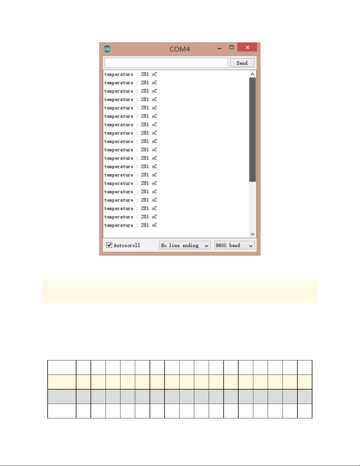
NOTE: This temperature was magnified 10 times, in the test, actual tempreture is 28.1 degrees
Celsius.
ServoRotationReferenceTable
Servo control command reference table:
DEC 0 1 2 3 4 5 6 7 8 9 10 11 12 13 14 15
HEX 0 01 02 03 04 05 06 07 08 09 0A 0B 0C 0D 0E 0F
Degree 0 6 12 18 24 29 35 41 47 53 59 65 70 76 82 88
DEC 16 17 18 19 20 21 22 23 24 25 26 27 28 29 30 31

HEX 10 11 12 13 14 15 16 17 18 19 1A 1B 1C 1D 1E 1F
Degree 94 100 106 112 117 123 129 135 141 147 153 159 164 170 176 182
DEC 32 33 34 35 36 37 38 39 40 41 42 43 44 45 46
HEX 20 21 22 23 24 25 26 27 28 29 2A 2B 2C 2D 2E
Degree 188 194 200 206 211 217 223 229 235 241 247 252 258 264 270
Arduino Sketch
NOTE: Please put the sensor jumpers to TTL mode. See above for a picture indicating TTL mode
// # Editor : Jiang from DFRobot
// # Data : 24.07.2012
// # Product name:ultrasonic scanner Kit
// # Product SKU:SEN0001

// # Version : 0.2
// # Description:
// # The Sketch for scanning 180 degree area 4-500cm detecting range
// # Connection:
// # Pin 1 VCC (URM V3.2) -> VCC (Arduino)
// # Pin 2 GND (URM V3.2) -> GND (Arduino)
// # Pin 4 PWM (URM V3.2) -> Pin 3 (Arduino)
// # Pin 6 COMP/TRIG (URM V3.2) -> Pin 5 (Arduino)
// # Pin mode: PWM
// # Working Mode: PWM passive control mode.
// # If it is your first time to use it,please make sure the two jumpers to t
he right hand
// # side of the device are set to TTL mode. You'll also find a secondary jum
per on
// # the left hand side, you must break this connection or you may damage you
r device.
#include <Servo.h> // Include Servo library
Servo myservo; // create servo object to
control a servo
int pos=0; // variable to store the
servo position
int URPWM=3; // PWM Output 0-25000us,e
very 50us represent 1cm
int URTRIG=5; // PWM trigger pin
boolean up=true; // create a boolean varia
ble
unsigned long time; // create a time variable
unsigned long urmTimer = 0; // timer for managing th
e sensor reading flash rate
unsigned int Distance=0;
uint8_t EnPwmCmd[4]={0x44,0x22,0xbb,0x01}; // distance measure comma
nd
This manual suits for next models
1
Table of contents
Popular Accessories manuals by other brands

Primrose
Primrose Drop Arm Awning instructions

Veris
Veris TW2 Protocol Series installation guide

ORION TELESCOPES & BINOCULARS
ORION TELESCOPES & BINOCULARS 8743 manual

Stahl
Stahl SolConeX 8570/16 Series operating instructions

Leviton
Leviton Renu RUAA1 Series quick start guide

Sandberg Active
Sandberg Active 10400 quick guide


