DF ROBOT DFR0004 User manual

(/wiki/index.php/File:RomeoV11.jpg)
DFRduinoRoMeoV1.1
DFRduinoRomeoAllinoneController
V1.1(SKU:DFR0004)
Contents
1 Introduction
2 Specification
3 DFRduinoRoMeoPinout
4 Beforeyoustart
4.1 ApplyingPower
4.2 Software
5 RomeoConfiguration
5.1 ServoPowerSelectJumper
5.2 MotorControlPinJumper
6 Tutorial
6.1 ButtonPress
6.2 ExampleuseofButton15
7 DualDCMotorSpeedControl
7.1 HardwareSetting
7.2 PinAllocation
7.3 PWMControlMode
7.4 PLLControlMode
8 Schematics
Introduction
RoMeoisanAllinOnemicrocontrollerespeciallydesignedforroboticsapplication.Benefit
fromArduinoopensourceplatform,itissupportedbythousandsofopensourcecodes,and
canbeeasilyexpandedwithmostArduinoShields.Theintegrated2wayDCmotordriverand
wirelesssocketgivesamucheasierwaytostartyourroboticproject.
Note:
A.Pleasereadthismanualcarefullybeforeapplyingpoweronthedevice.
B.Donotusethisdeviceformilitaryormedicalpurposeastheyarenotdesignedto.
Specification
Atmega168/328
14ChannelsDigitalI/O
6PWMChannels(Pin11,Pin10,Pin9,Pin6,Pin5,Pin3)
8Channels10bitAnalogI/O
USBinterface
Autosensing/switchingpowerinput
ICSPheaderfordirectprogramdownload
SerialInterfaceTTLLevel
SupportAREF
SupportMaleandFemalePinHeader
IntegratedsocketsforAPC220RFModuleandDFBluetoothModule
FiveI2CInterfacePinSets

TwowayMotorDrivewith2Amaximumcurrent
5keyinputs
DCSupply:USBPoweredorExternal7V~12VDC。
DCOutput:5V/3.3VDCandExternalPowerOutput
Dimension:90x80mm
DFRduinoRoMeoPinout
(/wiki/index.php/File:Romeo_v1.1_pinout_Diagram.png)
Fig1:RomeoPinOut
ThepictureaboveshowsalloftheI/OlinesandConnectorsontheRomeo,whichincludes:
OneRegulatedMotorPowerInputTerminal(6vto12v)
OneUnregulatedServoPowerInputTerminal(yousupplyregulated4vto7.2v)
OneServoinputpowerselectionjumper
OneSerialInterfaceModuleHeaderforAPC220/BluetoothModule
TwoDCMotorTerminals–Handlesmotorcurrentdrawupto2A,eachterminal
OneI2C/TWIPort–SDA,SCL,5V,GND
OneAnalogPortwith8analoginputs–Analoginput7willbeoccupiedwhenconnecting
"A7"jumper
OneGeneralPurposeI/OPortwith13I/Olines–4,5,6,7canbeusedtocontrolmotors
OneResetButton
JumperbanktoEnable/DisableMotorControl
Beforeyoustart
ApplyingPower

ApplyingPower
ThisisoneofthemostimportantstepsingettingtheRomeoupandcommunicatingwithyour
hostcontroller.YouMUSTmakesurethatyouapplypowertothePowerTerminalusingthe
correctpolarity.ReversePolaritywilldamagetheRomeo.Wearenotresponsibleforsuch
damage,nordowewarrantyagainstsuchdamage.Makesureyoutaketimetoapplypower
correctly.Otherwise,itcouldgetcostlyforyou!
PowerfromUSB:SimplyplugUSBcable,andtheRomeoisabletowork.Pleasenoticethat
theUSBcanonlysupply500mAcurrent.Itshouldbeabletomeetthemostrequirementsfor
LEDlitapplication.HoweveritisnotenoughtopowerDCmotorsorservo.
PowerfromMotorPowerInput:Simplyconnectthegroundwirefromyoursupplytothe
screwterminallabeled“GND”,andthenconnectthepositivewirefromyoursupplytothescrew
terminallabeled“VIN".
NOTE:Maximumsupplyvoltagecannotexceed14VDC.
Software
RoMeocanbeprogrammedbyArduinoIDE0022andabove.Itcanbedownloadedat
Arduino.cc(http://arduino.cc/en/Main/Software),Pleaseselect“ArduinoUNO”asthehardware.
RomeoConfiguration
ServoPowerSelectJumper
AsmostservosdrawmorecurrentthantheUSBpowersourcecansupply.Aseparateservo
powerterminalisprovidedtopowertheservoindividually.ThisoptioncanbeEnabled/Disabled
bytheServoPowerSelectJumper.
WhentheServoPowerSelectJumperisapplied,theservoispoweredbyinternal5V.
WhentheServoPowerSelectJumperisnotapplied,theservoispoweredbyexternalpower
source.
TheRomeoV1.0usesanautomaticswitcherforthepowersourceselection.Whentheexternal
powersourcehasbeenapplied,theservowillbeautomaticallypoweredbytheexternalpower
insteadofUSBpower.
MotorControlPinJumper
ApplyingtheMotorControlPinJumperswillallocatePin5,6,7,8formotorcontrol.
RemovingthejumperswillreleasetheabovePins,andthemotorcontrollerwillbedisabled.
Tutorial
ButtonPress
RoMeohas5buildinbuttonsS1S5(Figure2).S1S5useanaloginput7,
"ButtonPinMap"
Pin Function
AnalogPin7 ButtonS1S5


charmsgs[5][15]={
"RightKeyOK",
"UpKeyOK",
"DownKeyOK",
"LeftKeyOK",
"SelectKeyOK"};
charstart_msg[15]={
"Startloop"};
intadc_key_val[5]={
30,150,360,535,760};
intNUM_KEYS=5;
intadc_key_in;
intkey=‐1;
intoldkey=‐1;
voidsetup(){
pinMode(13,OUTPUT);//we'llusethedebugLEDtooutputaheartbeat
Serial.begin(9600);
/*Printthatwemadeithere*/
Serial.println(start_msg);
}
voidloop()
{
adc_key_in=analogRead(7);//readthevaluefromthesensor
digitalWrite(13,HIGH);
/*getthekey*/
key=get_key(adc_key_in);//convertintokeypress
if(key!=oldkey){//ifkeypressisdetected
delay(50);//waitfordebouncetime
adc_key_in=analogRead(7);//readthevaluefromthesensor
key=get_key(adc_key_in);//convertintokeypress
if(key!=oldkey){
oldkey=key;
if(key>=0){
Serial.println(adc_key_in,DEC);
Serial.println(msgs[key]);
}
}
}
digitalWrite(13,LOW);
}
//ConvertADCvaluetokeynumber
intget_key(unsignedintinput)
{
intk;
for(k=0;k<NUM_KEYS;k++)
{
if(input<adc_key_val[k])
{
returnk;
}
}
if(k>=NUM_KEYS)
k=‐1;//Novalidkeypressed
returnk;
}
DualDCMotorSpeedControl
HardwareSetting

ConnectfourmotorwirestoMotorTerminal.Andapplypowerthroughmotorpowerterminal
(Figure4).
(/wiki/index.php/File:RomeoSample.png)
Fig3:RomeoMotorConnectionDiagram
PinAllocation
"PWMMode"
Pin Function
Digital4 Motor1Directioncontrol
Digital5 Motor1PWMcontrol
Digital6 Motor2PWMcontrol
Digital7 Motor2Directioncontrol
"PLLMode"
Pin Function
Digital4 Motor1Enablecontrol
Digital5 Motor1Directioncontrol
Digital6 Motor2Directioncontrol
Digital7 Motor2Enablecontrol
PWMControlMode
(/wiki/index.php/File:RomeoMotorJmp.png)
Fig4:PWMMotor
ControlPin
Allocation

ThePWMDCmotorcontrolisimplementedbymanipulatingtwodigitalIOpinsandtwoPWM
pins.Asillustratedinthediagramabove(Figure5),Pin4,7(7,8foroldRomeoversion)are
motordirectioncontrolpins,Pin5,6(6,9foroldRomeoversion)aremotorspeedcontrolpins.
ForpreviousRomeoboard,thepinsusedtocontrolthemotorisPin7,8(Direction),Pin6,9
(Speed).YoucanfindtheinformationattherightsideoftheMotorControlPinJumpers.
SampleCode:

//StandardPWMDCcontrol
intE1=5;//M1SpeedControl
intE2=6;//M2SpeedControl
intM1=4;//M1DirectionControl
intM2=7;//M1DirectionControl
///ForpreviousRomeo,pleaseusethesepins.
//intE1=6;//M1SpeedControl
//intE2=9;//M2SpeedControl
//intM1=7;//M1DirectionControl
//intM2=8;//M1DirectionControl
voidstop(void)//Stop
{
digitalWrite(E1,LOW);
digitalWrite(E2,LOW);
}
voidadvance(chara,charb)//Moveforward
{
analogWrite(E1,a);//PWMSpeedControl
digitalWrite(M1,HIGH);
analogWrite(E2,b);
digitalWrite(M2,HIGH);
}
voidback_off(chara,charb)//Movebackward
{
analogWrite(E1,a);
digitalWrite(M1,LOW);
analogWrite(E2,b);
digitalWrite(M2,LOW);
}
voidturn_L(chara,charb)//TurnLeft
{
analogWrite(E1,a);
digitalWrite(M1,LOW);
analogWrite(E2,b);
digitalWrite(M2,HIGH);
}
voidturn_R(chara,charb)//TurnRight
{
analogWrite(E1,a);
digitalWrite(M1,HIGH);
analogWrite(E2,b);
digitalWrite(M2,LOW);
}
voidsetup(void)
{
inti;
for(i=4;i<=7;i++)
pinMode(i,OUTPUT);
Serial.begin(19200);//SetBaudRate
Serial.println("Runkeyboardcontrol");
}
voidloop(void)
{
if(Serial.available()){
charval=Serial.read();
if(val!=‐1)
{
switch(val)
{
case'w'://MoveForward
advance(255,255);//moveforwardinmaxspeed
break;
case's'://MoveBackward
back_off(255,255);//movebackinmaxspeed
break;

case'a'://TurnLeft
turn_L(100,100);
break;
case'd'://TurnRight
turn_R(100,100);
break;
case'z':
Serial.println("Hello");
break;
case'x':
stop();
break;
}
}
elsestop();
}
}
PLLControlMode
TheRomeoalsosupportsPLLPhaselockedloop(/wiki/index.php/Phase_locked_loop)control
mode.
(/wiki/index.php/File:Romeov11xxx.png)
Fig5:PLLMotor
ControlPin
Allocation
Configuration
SampleCode:

//StandardDLLSpeedcontrol
intE1=4;//M1SpeedControl
intE2=7;//M2SpeedControl
intM1=5;//M1DirectionControl
intM2=6;//M1DirectionControl
///ForpreviousRomeo,pleaseusethesepins.
//intE1=6;//M1SpeedControl
//intE2=9;//M2SpeedControl
//intM1=7;//M1DirectionControl
//intM2=8;//M1DirectionControl
//Whenm1p/m2pis127,itstopsthemotor
//whenm1p/m2pis255,itgivesthemaximumspeedforonedirection
//Whenm1p/m2pis0,itgivesthemaximumspeedforreversedirection
voidDriveMotorP(bytem1p,bytem2p)//DriveMotorPowerMode
{
digitalWrite(E1,HIGH);
analogWrite(M1,(m1p));
digitalWrite(E2,HIGH);
analogWrite(M2,(m2p));
}
voidsetup(void)
{
inti;
for(i=6;i<=9;i++)
pinMode(i,OUTPUT);
Serial.begin(19200);//SetBaudRate
}
voidloop(void)
{
if(Serial.available()){
charval=Serial.read();
if(val!=‐1)
{
switch(val)
{
case'w'://MoveForward
DriveMotorP(0xff,0xff);//Maxspeed
break;
case'x'://MoveBackward
DriveMotorP(0x00,0x00);
;//Maxspeed
break;
case's'://Stop
DriveMotorP(0x7f,0x7f);
break;
}
}
}
}
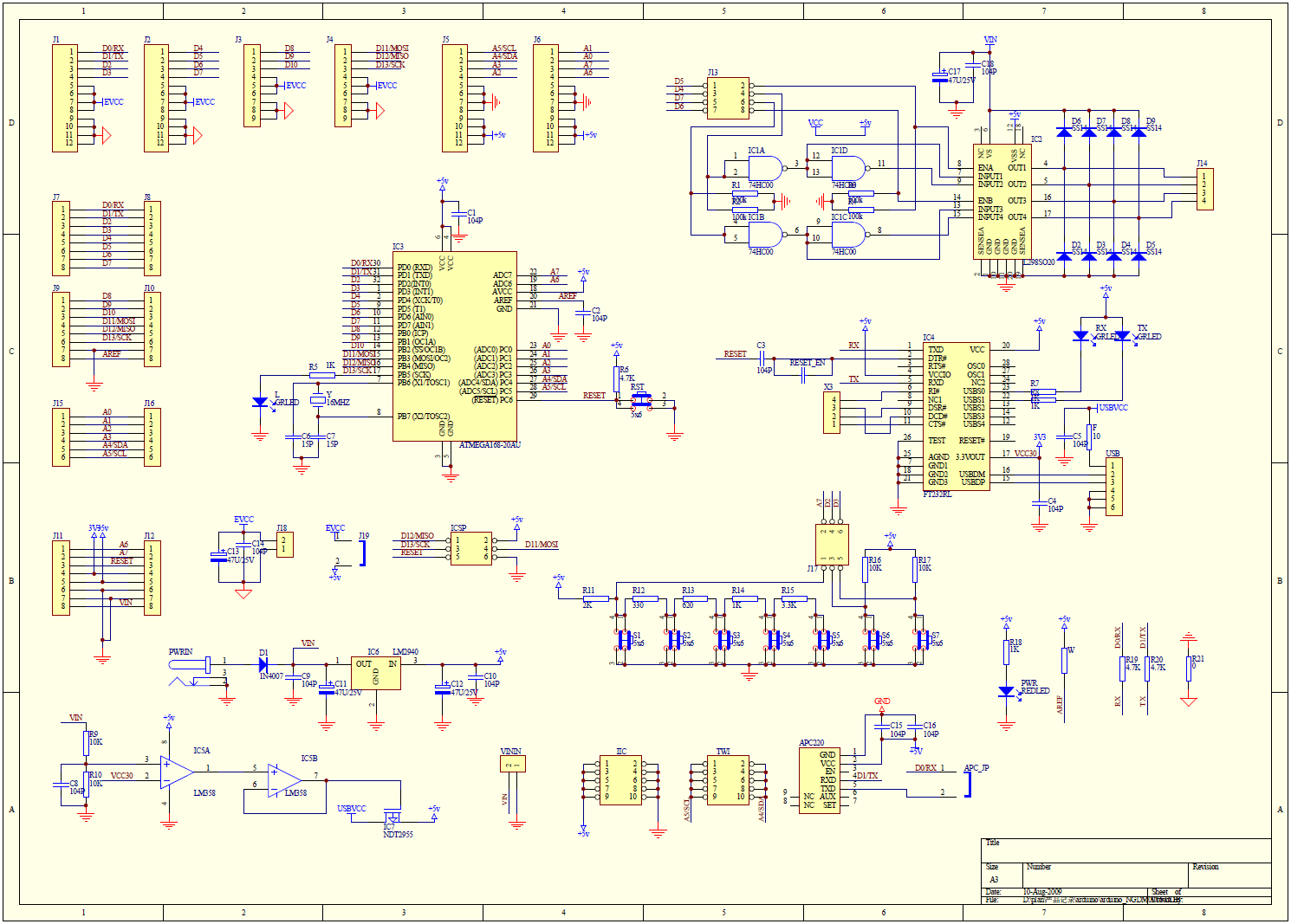
Schematics
schematic(http://www.dfrobot.com/image/data/DFR0004/RoMeo%20V1.1%20sch.pdf)
RomeoSchematicV1.0
(http://www.dfrobot.com/image/data/DFR0004/RoMeo_Schematic_V1.pdf)
RomeoSchematicV0.9(http://www.dfrobot.com/wiki/images/a/a0/RoMeo_Schematic.png)
Other manuals for DFR0004
1
Table of contents
Other DF ROBOT Controllers manuals


Popular Controllers manuals by other brands

Digiplex
Digiplex DGP-848 Programming guide

YASKAWA
YASKAWA SGM series user manual

Sinope
Sinope Calypso RM3500ZB installation guide

Isimet
Isimet DLA Series Style 2 Installation, Operations, Start-up and Maintenance Instructions

LSIS
LSIS sv-ip5a user manual

Rockwell Automation
Rockwell Automation 1769-L31 installation instructions


