DFE TI-11 User manual

INSTRUCTION MANUAL
MODEL TI-11
DOC 801-0545 R2

217 Pickering Road
Rochester, NH 03867-4630 U.S.A.
For assistance, please call:
TECHNICAL SERVICE - Installations, Start-Up, Troubleshooting, Repairs, Field
Service, Returns.
CUSTOMER SERVICE - Replacement Parts, Individual Products, Questions
about Orders, Manuals.
SALES - Product Information, Systems Application Questions,
Placing orders for standard products and special
systems.
Telephone: (603) 332-6150 Fax: (603) 332-3758
E-mail: info@dfe.com Internet: www.dfe.com
©2003 Dover Flexo Electronics, Inc. All rights reserved. Dover Flexo Electronics has made reasonable effort to ensure accuracy of this
document. However NO WARRANTY, whether expressed or implied, is given regarding the completeness or correctness of information in
this document. Dover Flexo Electronics shall not be liable for damages of any kind arising from the use or misuse of this document. Dover
Flexo Electronics reserves the right to make changes, additions, and deletions to this document without notice and without obligation.

TABLE OF CONTENTS
SECTION ONE DESCRIPTION PAGE
1.1 General Description 1
1.2 Outputs 1
1.3 TI-11 Exploded View 1
1.4 Specifications 2
1.5 Standard Features
0-10 Volt Tension Output 2
Meter Damping 2
Power Voltage Selection 2
4-20ma Tension Output 2
0-1mA Tension Output 2
Status Lights 2
Diagnostic Connector 2
1.6 Options
230 Volt Power 2
Extended Range 2
0-100mv Tension Output 2
0 to -10V Tension Output 2
Isolation From Earth Ground 3
1.7 Accessories 3
1.8 Front Panel 3
SECTION TWO INSTALLATION
2.1 Dimensions 4
2.2 Installing the Circuit Card 5
2.3 Electrical Connections 6
2.4 Electrical Connections to Plug-in Adapter 6
SECTION THREE CALIBRATION AND SETUP
3.1 Mechanically Zero The Tension Meter 7
3.2 Calibrate The Meter For Accuracy 7
3.3 The TI-11 Circuit Card 8
3.4 Power Voltage Selection 8
3.5 Tension Meter Outputs 9
3.6 4-20mA Current Outputs 9
3.7 High Voltage Outputs 9
3.8 Meter Damping 9
3.9 Extended Range 9
3.10 Isolation From Earth Ground 9
SECTION FOUR OPERATING INSTRUCTIONS 10
SECTION FIVE CARE & MAINTENANCE 11

SECTION SIX TROUBLESHOOTING GUIDE
6.1 Troubleshooting Procedure 12
6.2 Diagnostic Connector 12
SECTION SEVEN REPLACEMENT PARTS 13
APPENDICES
APC Board and DIP Switch Settings 14
BElectrical Connections 15
CTransducer Electrical Connections 16
DTypical Tensions 20
TERMS AND CONDITIONS OF SALE 21
DECLARATION OF CONFORMITY 22
INDEX 23
LIST OF ILLUSTRATIONS
FIGURE DESCRIPTION PAGE
1 TI-11 Exploded View 1
2 Front Panel 3
3 Dimensions 4
4 Optional Plug-in Adapter Dimensions 4
5 Optional Analog Meter Dimensions 5
6 Meter Mounting Dimensions 5
7 Electrical Connections 6
8 Electrical Connections to Plug-in Adapter 6
9 Web Path 7
10 TI-11 Circuit Card 8
11 Power Selection Switch 8
12 Diagnostic Connector 12
13 TI-11 PC Board 14
14 Electrical Connections, Standard 15
15 Optional Electrical Connections 15
16 Transducer Wiring, Models C and UPB 16
17 Transducer Wiring, Model RF 17
18 Transducer Wiring, Models TR and NW 18
19 Transducer Wiring, Model LT 19
1
SECTION 1 DESCRIPTION
1.1 GENERAL DESCRIPTION
The TI-11 dual tension indicator is a device to output and display tension measurements. It can be used
with any type of DFE tension transducer to display actual web tension on an analog or digital meter for
reference by the machine operator. It also has voltage and current outputs that are proportional to tension,
and which can be connected to tension recorders, variable speed drive systems, computers, and other
devices for tension control or display purposes. The TI-11 contains two independent tension indicator
circuits on one card. Each has its own calibration adjustments and outputs. The card is an
IEC/ANSI/IEEE type 2 plug-in unit for installation in a standard size 3U 19 inch rack.
1.2 OUTPUTS
Each tension indicator circuit has three outputs.
A. 0 to 1mA (standard) or 0 to 100mV, selectable. Usually used for a tension indicating meter.
B. 4 to 20 mA
C. 0 to +10 Vdc (standard) or 0 to -10 Vdc, selectable and adjustable for 3.5 to 12 Vdc
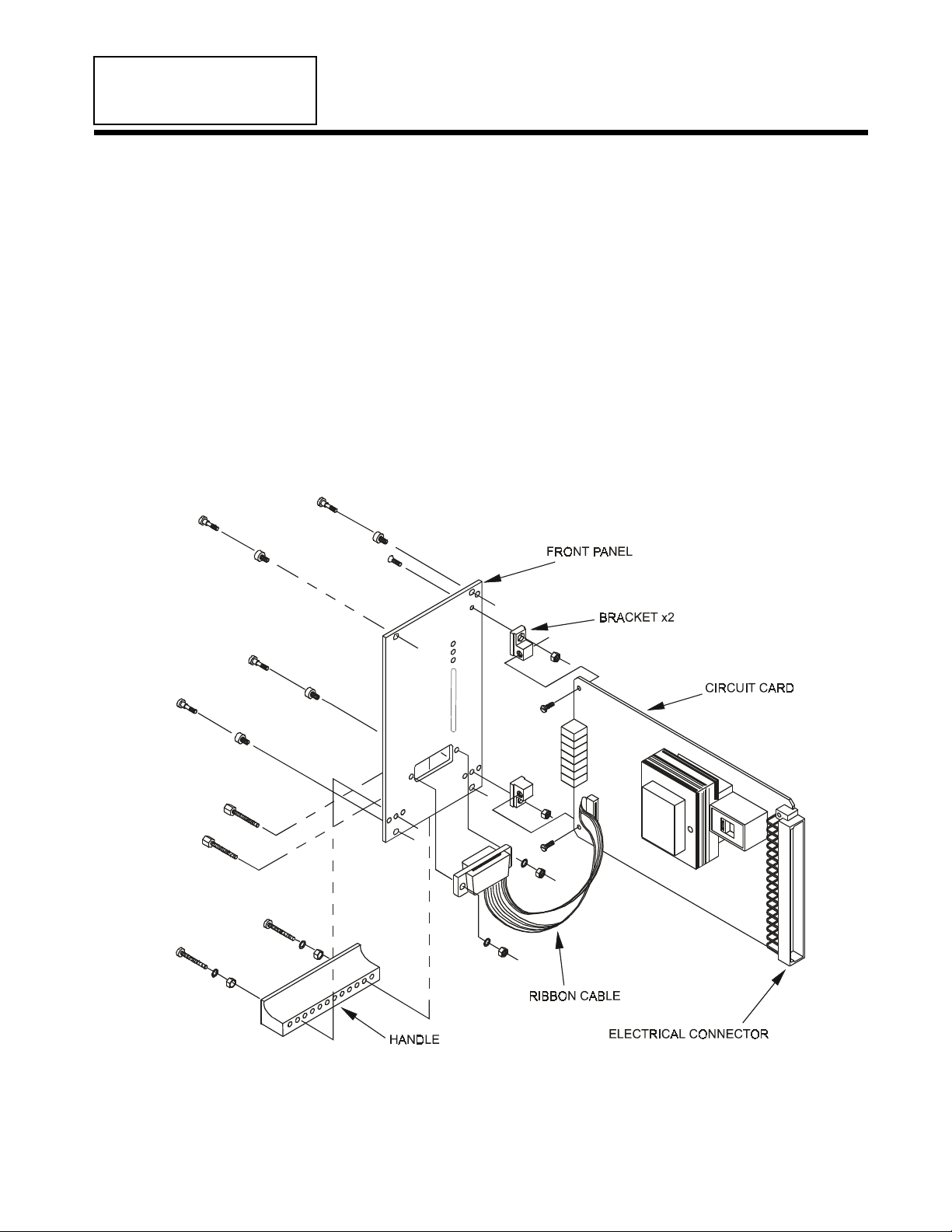
1.3 TI-11 INDICATOR EXPLODED VIEW
Figure 1 - TI-11 INDICATOR- EXPLODED VIEW

2
1.4 SPECIFICATIONS
Power Input . . . . . . . . ................... 115 Volts 60/50Hz single phase @ 1 Amp
230 Volts 60/50Hz single phase @ 1/2 Amp
Earth Ground Connection ................. Circuit-commonconnected to earth ground by the AC
power ground connection.
TensionSignalOutputs .................. 0to+10Vdc@2mAOR4-20mA
. [ or 0 to -10 Vdc @ 2mA Optional]
TensionMeterOutputs ................... 0to1mA
[ or 0 to 100mV @ 10mA , or 0 to +10Vdc @ 2mA
Optional]
Weight ............................ 1.15 lbs. (0.5 Kg)
TransducerSignalIn..................... 500 mVdc at rated load
TransducerExcitation.................... 5Vdc (10VdcwithXRoption)
MatingCircuitCardConnector ............ VERO#17-2873H or equivalent
MatingDiagnosticConnector.............. MaleDB15. AMP #745494-6 or equivalent
Zero(Tare)Range ...................... 95%oftransducerrating,minimum
CalibrationRange....................... 25:1
TemperatureRange...................... 32°Fto104° F (0° C to 40° C)
SystemAccuracy ....................... 1-3%typical
TensionMeter(optional) ................. Analog,2%,1mA,48ohm
StandardTensionMeterScales ............ 0-1,5,10, 25, 50, 100, 150, 250, 500, 1000
(tension meter is optional)
1.5 STANDARD FEATURES
SOME OF THESE FUNCTIONS REQUIRE CONFIGURING OR EXTERNAL WIRING. REFER TO
SECTION 3 FOR CONFIGURING AND SECTION 2 FOR WIRING.
•0 to +10 Volt dc Tension Output. Proportional to web tension. Used as an input to other control
systems, computers or data collection devices. Adjustable.
•Meter Damping. Minimizes vibration of the optional analog tension meter needle.
•Power Voltage Selection. The TI-11 Indicator is designed to operate on two ranges of AC power;
115 Volts 60/50 Hz, and 230 Volts 60/50 Hz. A switch on the circuit board selects between the two.
•4-20mA Tension Output. Used as an input to control systems, computers, or data collection devices.
•0-1mA Tension Output.Typically used for an input to a tension readout meter.
•Status Lights. Shows status of power supplies.
•Diagnostic Connector. Located on front panel. Permits inputs and outputs to be checked easily.
1.6 OPTIONS (The option code is shown in parentheses)
SOME OF THESE OPTIONAL FUNCTIONS REQUIRE CONFIGURING OR EXTERNAL WIRING.
REFER TO SECTION 3 FOR CONFIGURING AND SECTION 2 FOR WIRING.
•230 Volt Power (230V). 230 volt 50/60 Hz power input.
•Extended Range (XRE). 10Vdc excitation for transducers. Allows measurement of much lower
tension than usual. Transducers must also have the XR option. WARNING! If one tension indicator
circuit requires XR, then the other must use it too. Both circuits must use the same transducer voltage.
Both sets of transducers must have the XR option even if only one requires it for tension range.
•0-100 mV Tension Output (100MV). Alternate to the standard 0-1mA meter output.
•0 to 10 Vdc Tension Output (10V).Alternate to the standard 0-1mA meter output.
•0 to -10 Vdc Tension Output (-10V). Replaces the standard 0 to +10 Volt dc output.
3
•Isolation From Earth Ground (IFEG). Removal of a jumper allows the TI-11 to float at a variable
electrical potential above earth ground. The jumper disconnects the circuit- common pc board trace
from the earth-grounded pin on the electrical connector. This can eliminate ground-loop problems or
output polarity contentions between the TI-11 and devices connected to its outputs. However, if the
jumper is removed, one of the devices connected to the TI-11 outputs MUST be grounded. This will
prevent the TI-11 from floating far enough above ground potential to cause problems. If no ground
connection exists, it is possible that the transducers may short-circuit to ground at the strain gages. The
result being electrical failure of the transducers. Must apply to both indicator circuits.
1.7 ACCESSORIES
•Analog Tension Meter (AM). 1mA, 48 Ohm movement. Must be remotely installed. A separate
meter is required for each tension circuit. DFE part #722-1385.
•Nonstandard Meter Scale (NMS). Any nonstandard analog meter scale. See Specifications, page 2,
for standard scales.
•Type 5 Plug-in Adapter. Plug the TI-11 into this adapter instead of a 19 inch rack. Terminal strips for
hard-wired connections. Install the unit in your own enclosure.
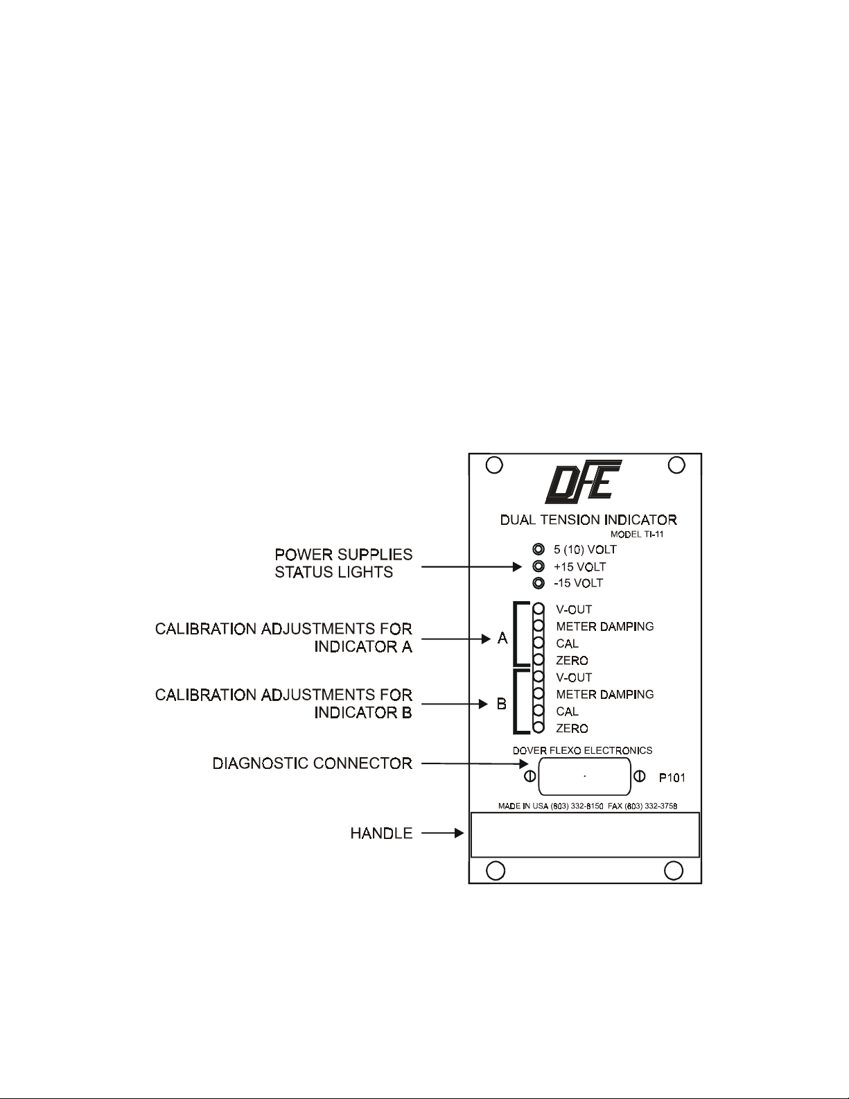
1.8 FRONT PANEL
Figure 2 - FRONT PANEL
4
SECTION 2 INSTALLATION
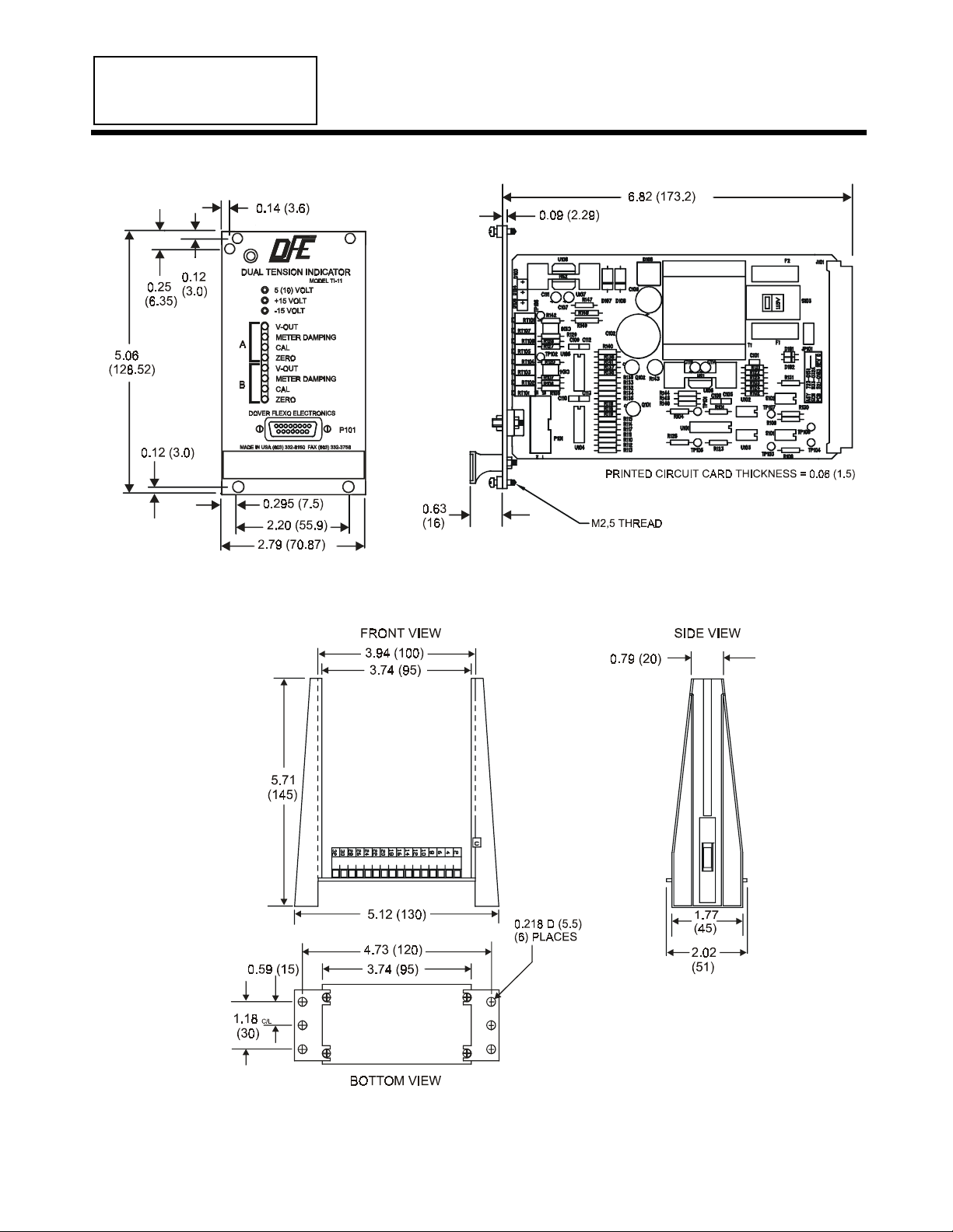
2.1 DIMENSIONS inches (mm)
Figure 3 - DIMENSIONS
DIMENSIONS OF OPTIONAL PLUG-IN ADAPTER inches (mm)
Figure 4 - OPTIONAL PLUG-IN ADAPTER

5
DIMENSIONS OF OPTIONAL ANALOG TENSION METER inches (mm)
Figure 5 - OPTIONAL ANALOG METER
MOUNTING DIMENSIONS FOR ANALOG METER inches (mm)
Figure 6 - METER MOUNTING DIMENSIONS
2.2 INSTALLING THE CIRCUIT CARD
The TI-11 is plugged into a standard 19 inch rack having an opening 3U high by 14HP wide. The
optional plug-in adapter may also be used.
Note: The TI-11 has been tested to meet the EMC directive, and for that compliance, the unit must be
installed in a shielded enclosure and used with shielded cables (Dover cables are shielded).

6
2.3 ELECTRICAL CONNECTIONS
Refer to the drawing below for electrical connections to the rear connector of the TI-11.
Figure 7 - ELECTRICAL CONNECTIONS
2.4 ELECTRICAL CONNECTIONS TO PLUG-IN ADAPTER
Figure 8 - ELECTRICAL CONNECTIONS TO PLUG-IN ADAPTER

7
SECTION 3 CALIBRATING AND SETUP
The TI-11 has two independent tension indicating circuits. Each must be calibrated properly so the
outputs accurately represent actual web tension. The best way to do this is to attach the optional tension
meter (having a 1mA, 48 ohm movement) to the 0-1mA output and follow the procedure below.
Optionally, use the diagnostic connector pin 11 for the common and pin 2(+) for circuit A, and pin 11(-)
to pin 1 (+) for circuit B. Zero at zero volts, cal to a proportional value of 10 volts = max. tension value.
Actual voltage is determined by the weight you hang in step E. So, to cal for 0-50 lbs. using a 25 lb.
weight, set the cal pot for a 5.0 volt reading. (25 lb. wt. is 1/2 of the 50 lb. max. desired, 5V is 1/2 of the
10V full out pot reading) Start with tension indicator circuit A.
3.1 MECHANICALLY ZERO THE TENSION METER
This step is only necessary if the tension meter needle does not rest on 0 when the power is turned off.
Turn off power to the TI-11. Turn the adjustment screw on the rear of the meter as required to set the
meter needle at 0 on the scale.
3.2 CALIBRATE THE METER FOR ACCURACY (Refer to Fig. 2 or 10 for adjustment pots.)
1. Find an object of known weight at least as heavy as 25% of the tension meter full scale number. (a
spring scale can also be used). Get a length of rope, wire or cable about 15 ft.(3M) long.
2. Turn on power to the TI-11.
3. Turn the CAL pot. clockwise 5 turns (This makes the ZERO pot. setting more accurate). Turn the
ZERO pot. as required to set the meter needle at 0.
4. Fasten one end of the rope in the machine and thread the other end around the transducer roll in
exactly the same path as the web will take. Be sure it does not pass around any driven rolls, drag bars,
or anything else that can affect tension. Refer to Figure 9 below.
Figure 9 - WEB PATH FOR METER CALIBRATION
5. Attach the weight to the free end of the rope as shown above. Adjust the CAL pot. as required to
set the meter needle at the value of the weight.
6. Remove the weight and observe the tension meter. If the needle is not on 0, adjust the ZERO pot. as
needed.
7. Repeat steps 5 and 6 if needed.
8. The adjustable 0-10 volt output is factory pre-set at 10 volts out with full scale meter deflection. If
the V-out setting has been altered or if you desire a different value range, set the zero pot to give
full scale reading on the tension meter, then adjust the V-out pot to achieve the desired maximum
output (normally 10 volts). Re-set the zero pot to a zero reading on the tension meter.
9. The 4-20mA output is automatically calibrated along with the 0-1ma output. No additional action
need be taken.
10. Adjust the METER DAMPING pot. while the machine is running to minimize meter needle
movement.
8
Now use the same procedure to calibrate tension indicator circuit B using pins 9 and 5 on the
Diagnostic Connector to measure the 10 volt output.
NOTE: If only one tension indicator circuit is used, it is not necessary to calibrate the other.
TENSION METER CALIBRATION IS COMPLETED.
Your TI-11 Dual Tension Indicator has been properly configured to your order at the factory. It should
not be necessary to make any changes. Use the following sections only to verify the configuration or to
reconfigure the indicator if your application requirements change.
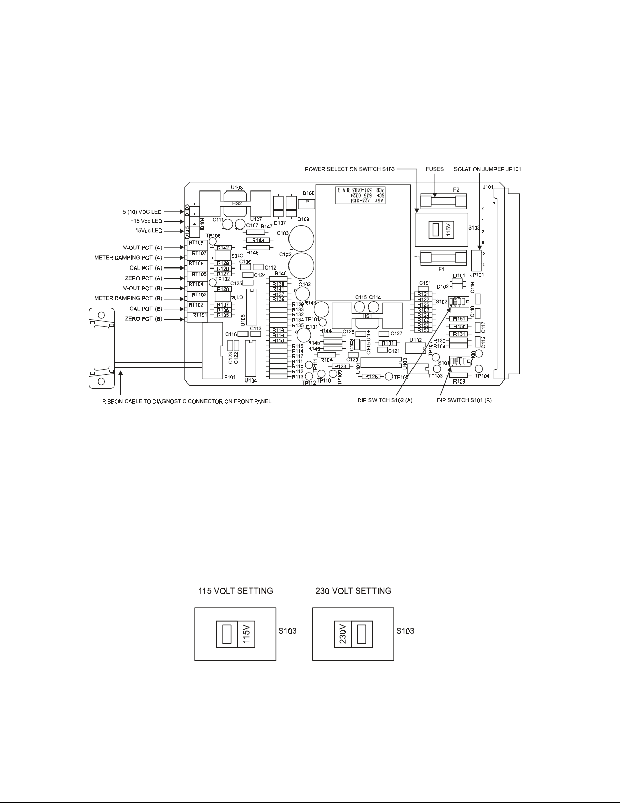
3.3 THE TI-11 CIRCUIT CARD
Figure 10 - TI-11 CIRCUIT CARD
3.4 POWER VOLTAGE SELECTION (See Figure 10, above)
The TI-11 indicator is designed to operate on either 115V-60Hz or 230V-50/60Hz power. Check to
confirm correct voltage selection on the S103 switch. Also check fuses for correct values:
1/4 A/250V for 115V 1/8 A/250V for 230V
Warning! Equipment must be disconnected from the HAZARDOUS LIVE voltage before changing the
fuses. To reduce the risk of fire, replace fuses only with the same type and rating.
CAUTION! The wrong selection will damage the Indicator!
Figure 11 - POWER SELECTION SWITCH S103

9
3.5 TENSION METER OUTPUTS (See Figure 10 above for switch locations)
Select the 0-1mA current outputs by setting switches on S101 (Indicator B) and S102 (Indicator A) DIP
switches. CAUTION - Do not operate with both switches 1 and 2 closed.
SWITCHES S101 AND S102
OUTPUT1234
0-1ma OPEN OPEN - -
0-100mV OPEN CLOSED --
0-10V CLOSED OPEN --
3.6 4-20 mA CURRENT OUTPUTS
No special set up is required. If the tension meter output is calibrated properly, this output will produce
4mA when the meter reads 0, and 20mA when the meter reads its full scale value.
3.7 HIGH VOLTAGE TENSION OUTPUTS
Select between 0 to +10 Vdc output and 0 to -10Vdc output by setting the appropriate switches on S101
(Indicator B) and S102 (Indicator A).
SWITCHES S101 AND S102
OUTPUT1234
0 to +10V
0 to -10V
-
-
-
-
-
-
CLOSED
OPEN
3.8 METER DAMPING (See Page 2 for description, Figure 10 for adjustment)
This adjustment steadies the analog tension meter needle. Turn the METER DAMPING pot. CW to
stabilize the meter reading. This only affects the meter. The tension output signals are not damped.
3.9 EXTENDED RANGE (See Page 2 for description)
Select between 5V and 10V excitation for the tension transducers. 10 Volts provides a wider operating
range. CAUTION - The transducers MUST have the XR option if you select 10 Volts! Otherwise
they will be damaged.
SWITCHES S101 AND S102
OUTPUT1234
5V
10V
-
-
-
-
CLOSED
OPEN
-
-
NOTES:
1. If either switch S101-3 or S102-3 is closed, transducer excitation is 5Vdc for both Indicator A and B.
2. If 10Vdc excitation is chosen for either Indicator, it is also applied to the other Indicator. Therefore if
only one Indicator requires transducers with the XR option, the other one must also use transducers
with the XR option.
3.10 ISOLATE FROM EARTH GROUND (See Page 3 for description and cautions)
Refer to Figures 10 and 7. Remove jumper JP101 to isolate the TI-11 from earth ground. One of the
devices connected to a TI-11 output must be grounded to prevent the TI-11 from floating too far above
ground potential. Otherwise, both sets of transducers may short-circuit to ground through the strain
gages.

10
SECTION 4 OPERATING INSTRUCTIONS
Your tension interface / indicator will indicate tension in your system without any further operator
intervention. It is a good idea to make a check at roughly one month intervals to verify that the output
returns to zero when no web is touching the transducer.

11
SECTION 5 CARE AND MAINTENANCE
It is not necessary to perform any type of maintenance on the indicator. However you may find it
worthwhile to observe whether there is a buildup of dust, debris, or moisture on or near the unit after a
period of time. If so, you may consider putting the unit in a more appropriate enclosure.

12
SECTION 6 TROUBLESHOOTING GUIDE
6.1 TROUBLESHOOTING PROCEDURE
1. Most problems are caused by incorrect installation and misapplication of the equipment. So it is very
important to be sure these factors are correct before making any changes to potentiometer and switch
settings.
If you would like assistance evaluating your installation, please call Technical service at (603) 332-
6150 (Fax: (603) 332-3758). We have experienced technicians whose responsibility it is to make
sure you are satisfied with your DFE equipment. They will be pleased to help.
2. The most common source of improper operation of tension equipment is incorrect installation of the
tension transducers or using transducers of the wrong load rating. Refer to your transducer
instruction manual and check the sizing and installation procedures to verify the installation.
NOTE: Avoiding pre-loading is very important for the "C" and "UPB" type transducers.
3. Verify the electrical connections to the TI-11 indicator. Refer to Appendices B and C. Also Section
2 or 3. Check fuses. If they need to be replaced, use the correct values listed below:
115V Operation = 0.25mA, 250V Slo Blo 230V Operation = 0.125mA, 250V Slo Blo
Warning! Equipment must be disconnected from the HAZARDOUS LIVE voltage before changing
the fuses. To reduce the risk of fire, replace fuses only with the same type and rating.
4. Proper calibration of the tension meter is very important to the operation of the indicator. Be sure
the calibration is correct. Refer to Section 3. Improper calibration may cause unstable operation if
the TI-11 output is connected to a drive system.
5. If the above steps are not successful, or if you get unexpected results in any step, call Technical
Service at (603) 332-6150 for assistance.
6.2 DIAGNOSTIC CONNECTOR
The diagnostic connector mounted on the front panel is used to check the TI-11 inputs and outputs
without having to use an extender board to access the test points on the circuit card.
Figure 12 - DIAGNOSTIC CONNECTOR

13
SECTION 7 REPLACEMENT PARTS
7.1 REPLACEMENT PARTS
DFE Part Number
Legend plate 323-0283
Handle and Fastener Kit 126-0006
Bracket Kit 126-0004
Tension meter, analog (option) 722-1385 (specify scale)
Plug-in adapter (option) 143-0000
Fuses: 115V = 1/4 A/250V Slo Blo 108-0046 *
230V = 1/8 A/250V Slo Blo 108-0045 *
Fuse cover 108-0005
Ribbon cable 721-1125
Instruction Manual 801-0545 R2
* To reduce the risk of fire, replace fuses only with the same type and rating.

14
Appendix A: PC Board & DIP Switches
Figure 13 - TI-11 PC BOARD
SWITCHES S101 AND S102
OUTPUT 1234
METER 10-1mA
0-100mv (Opt.)
0-10v (Opt.)
OPEN
OPEN
CLOSED
OPEN
CLOSED
OPEN
--
TRANSDUCER
EXCITATION 2, 3, 4
5V
10V
- - CLOSED
OPEN
-
HIGH POWER
OUTPUT
0 to +10V
0 to -10V
-
-
-
-
-
-
CLOSED
OPEN
NOTES: 1. Do not operate with switches 1 and 2 both closed. Damage may result.
2. If either switch S101-3 or S102-3 is closed, transducer excitation is 5V for both Indicators.
3. 10V transducer excitation requires that the transducers have the XR option.
4. If one Indicator requires transducers with the XR option, the other Indicator must also use
transducers with the XR option. There is only one power supply to excite both sets of
transducers.
STANDARD SETTINGS
The standard settings are: 0-1ma, 5V, and 0 to +10V. Any other settings are optional.
15
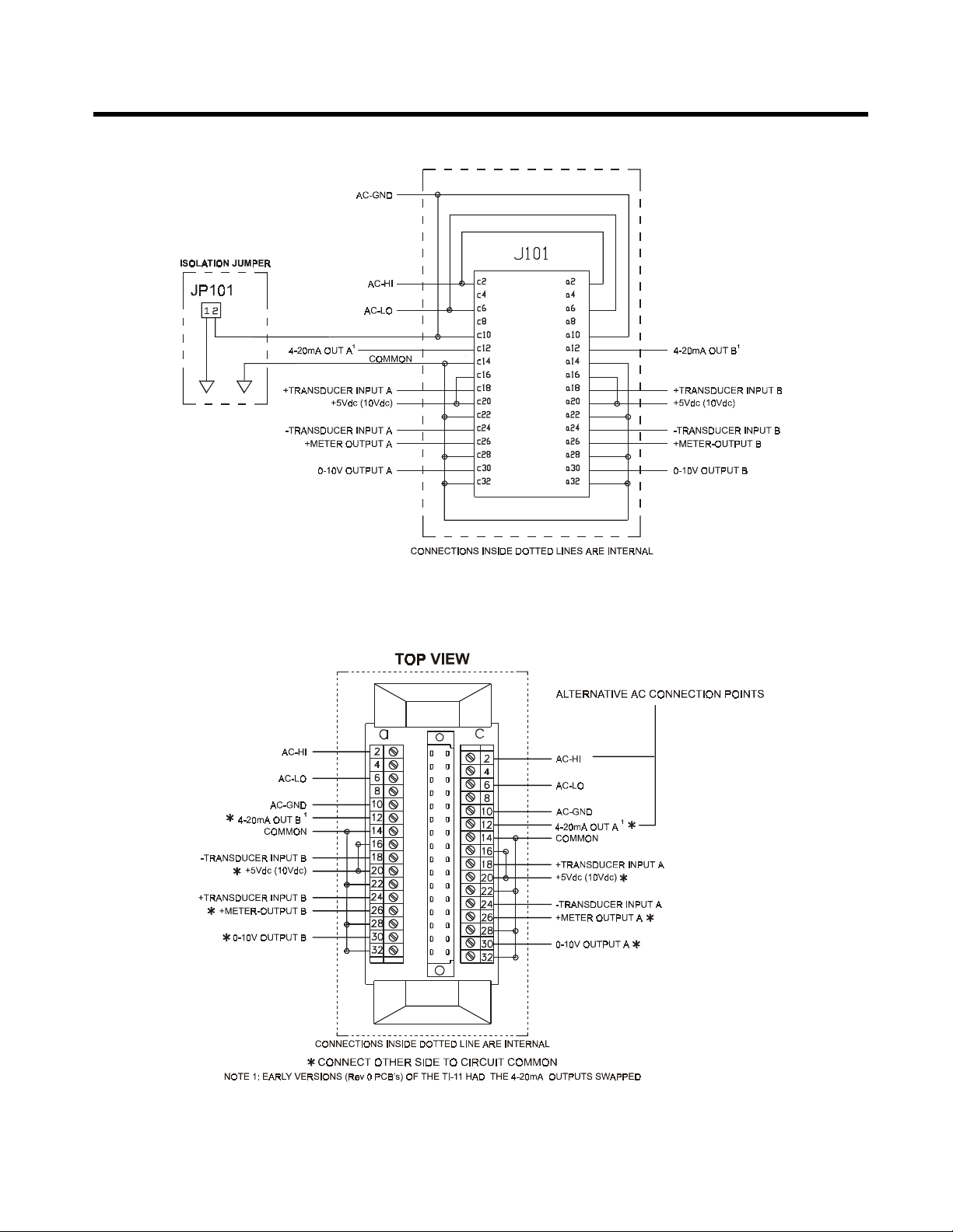
Appendix B: Electrical Connections
STANDARD ELECTRICAL CONNECTIONS
Figure 14 - STANDARD ELECTRICAL CONNECTIONS
OPTIONAL PLUG-IN ADAPTER ELECTRICAL CONNECTIONS
Figure 15 - OPTIONAL ELECTRICAL CONNECTIONS
16
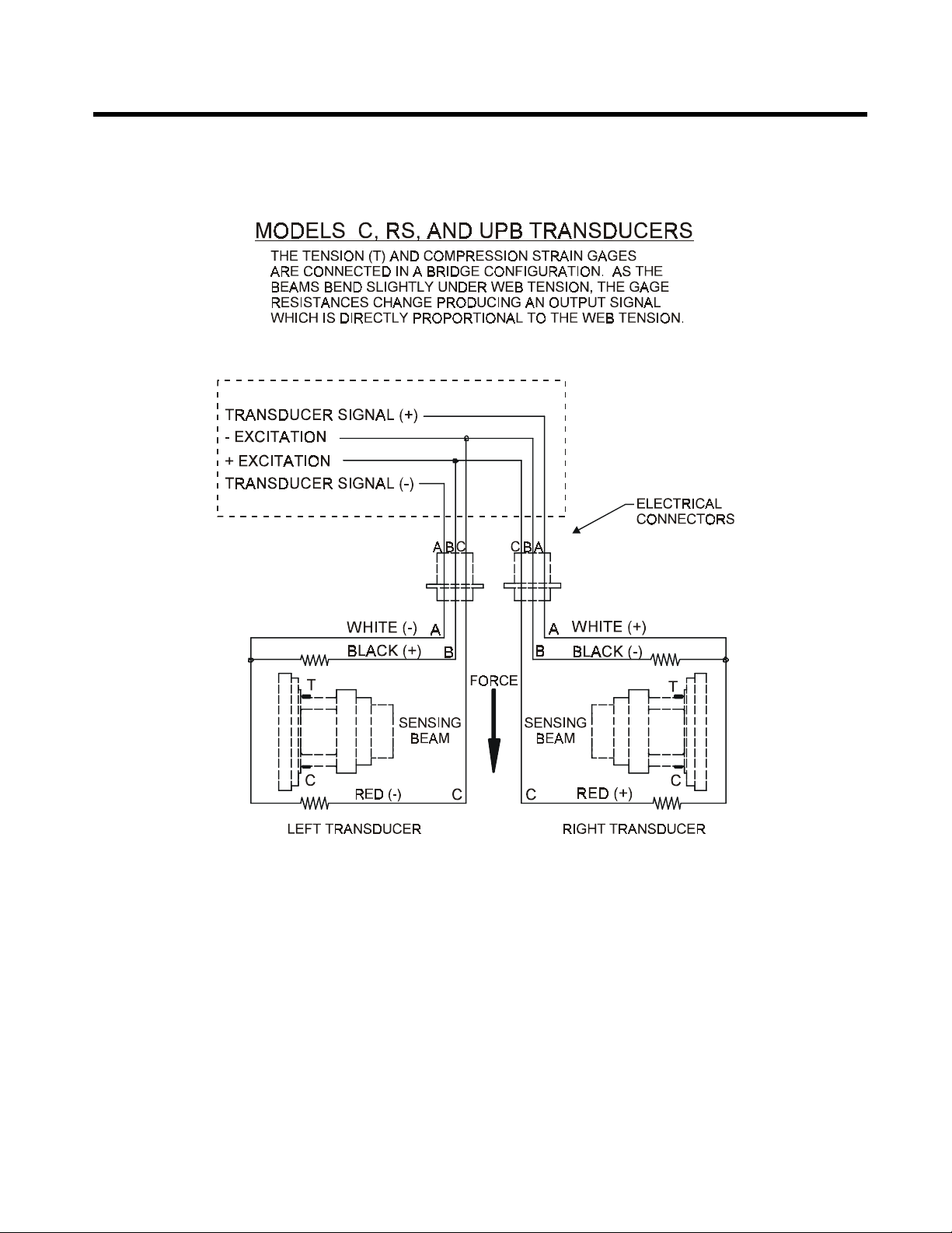
Appendix C: Transducer Electrical Connections
Figure 16 - MODELS C & UPB TRANSDUCER WIRING
Table of contents
Other DFE Measuring Instrument manuals


