DFI DUS R-50S User manual

User Manual
Urine Chemistry Analyzer
DU(V5). 2019.11

2
Contents
1. Introduction
2. System Description
2.1 Principles of Measurement
2.2 Components and Functions
2.3 Technical Information
2.4 Interfacing System
3. Instrument Installation
3.1 The instrument and parts
3.2 Optional accessories
3.3 Environmental & Storage Requirements
3.4 Cautions & Warnings
4. How to operate instrument
5. How to Use
6. Table Result
7. How to Clean the Strip Loading Plate after Use
8. Quality Control
9. Troubleshooting &Maintenance
Appendix A. Safety Information

3
WARNING
Please read the User’s Manual before you operate this instrument.
1) Never use the bent strip and make sure to remove excess urine in the
strip by using a clean absorbent soft tissue paper.
2) Clean instrument daily to prevent malfunction.
ToClean the instrument, Refer to 7. How to Clean the Strip Loading
Plate after Use.
3) If the equipment is used in a manner not specified by the
manufacturer, the protection provided by the equipment may be
impaired.
BIOHAZARD: Wear personal protective equipment. Use
universal precautions. Refer to Appendix A for recommended
precautions when working with biohazardous materials.

4
1.
Introduction
Urine test strips simplify diagnosis of disease through ease of use, high
sensitivity and specificity. These benefits allow you to identify pathological
changes in the urine quick and reliably. The addition of the Urine Analyzer
to the urinalysis process allows for standardization and efficiency of urine
test by eliminating potential sources of error associate with the visual
reading of test strips, such as improper lighting at the workplace, or
different color discrimination by the user or different timing when the
values are read. The urine test strips that shall be used with the instrument
are multi parameter strips for the determination of specific gravity, pH,
leukocytes, nitrite, protein, glucose, ketones, urobilinogen, bilirubin, blood,
microalbumin, creatinine and so on in urine.
2.
System Description
2.1 Principles of Measurement
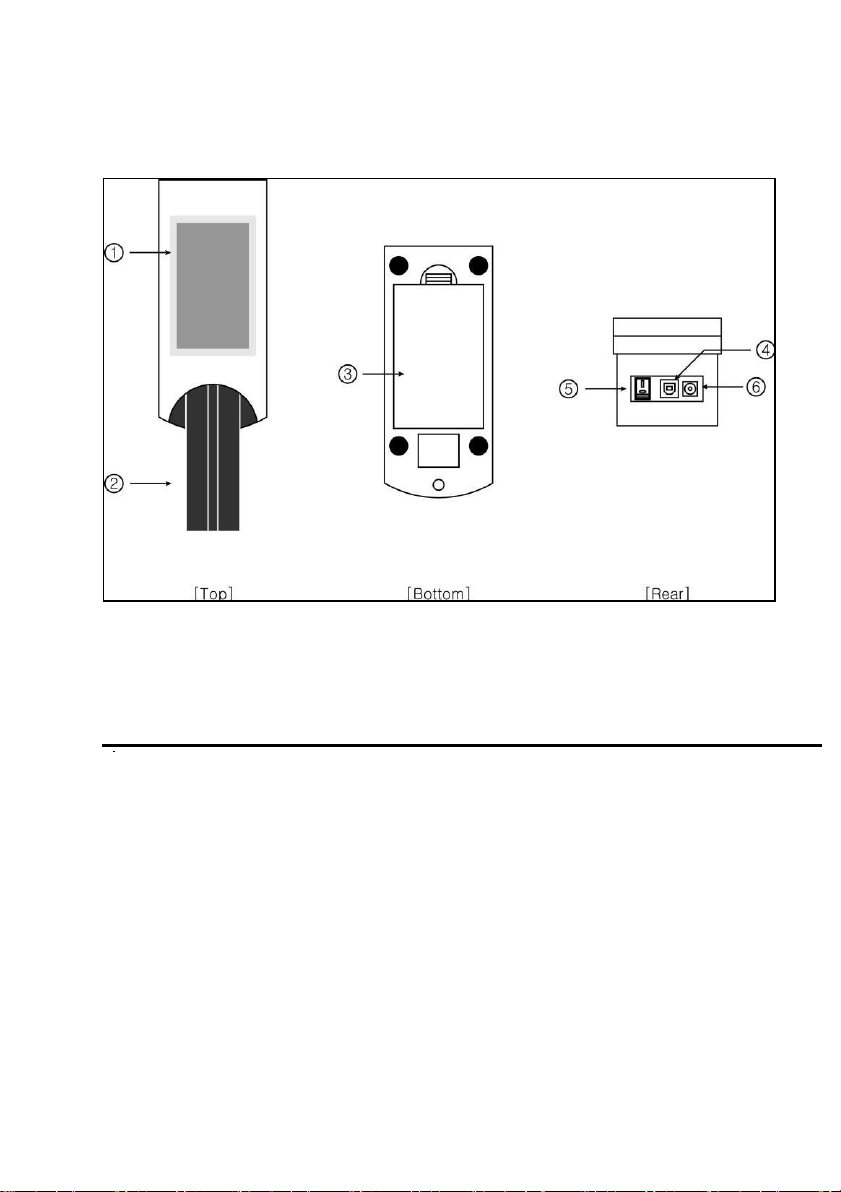
The DUS R-50S is a urine strip analyzing device. The reader is
semiautomatic but the forwarding, reading and evaluating are automated.
The only thing that the operator need to do is to dip the strip into the urine
sample and place it on the Strip Loading Plate.
The DUS R-50S is a reflectance photometer. The strip is illuminated by
white light and the reflected light from the strip is detected by the Sensor.
The RGB signals are digitized and this digitized image is interpreted by the
processor. The intelligent image analyzer SW locates the strip and the pads,
and based on these color data the parameter values are determined. The
results including the date and time of the measurement, sequence number
and ID are stored.

5
2.2 Components and Functions
View from above View of rear
Component Function
①Full-color ‘touch-screen’ TFT LCD: Displays the result and the
process of test
②Strip Loading Plate: Moves the test strip to the measuring position
③Battery cover
④USB Port: Serial interface port for connection to a PC or central
laboratory (host) computer or to the optional thermal printer
⑤Power Button: Turns on/off the system
⑥Power Connector: Socket used to connect the analyzer to the external
power supply

6
2.3 Technical Information
Measurement Method
Reflectance Photometer
Wave Length
470, 530, 626 nm
Dimensions
Width(188mm), Depth(74mm), Height(77mm)
Weight
400g
Power Supply
Input: 100-240V / Output: DC 12V, 3.33A
Battery
AAA 1.5V * 8ea
Throughput
40-50 / Hour (120 tests/hour under ‘Quick’
mode)
Memory
Up to 2000 samples
Operating Conditions
Temperature (2℃-30℃) / Humidity(10%-70%)
Serial Communication
USB Port
Options
External Printer
2.4 Interfacing System
Users can interface DUS R-50S to Host computer through the USB port.
Baud Rate: 38400, Data bit : 8, Parity: none

7
3.
Instrument Installation
3.1 The instrument and parts
DUS R-50S: 1EA
Strip Loading Plate: 1EA
AC adapter 100-240V / 12V DC 3.33A : 1EA
Power Cable: 1EA
Operating Manual
USB cable
3.2 Optional accessories
External Printer for exclusive use with DUS R-50S analyzer
Supplied with printer are:
-2paper print rolls.
-DC cord for power supply between printer and reader
To install the paper roll, open the cover of the printer and insert the roll so
that 1cm comes over the edge of the cutting teeth. Make sure to insert the
paper in the right direction. The printer can only print on one side of the
paper.
The correct driver software for operation with reader has already been
installed on the printer. To start operation with the instrument, connect USB

8
cable and power cords as follows:
3.3 Environmental & Storage Requirements
3.3.1 Environmental Requirements
As with all sensitive electronic instruments, prolonged exposure to
excessive humidity and temperature should be avoided. Place the
instrument where it will not be subjected to extreme temperature variations.
Avoid proximity to open windows, direct sunlight, ovens, hot plates, open
burners, radiators, and dry ice baths.

9
3.3.2 Storage and Handling
Avoid following locations to prevent malfunctioning of the analyzer
•
High humidity, high-temperature, and low-temperature storage places
•
Dusty places
•
Veryhot places near heating appliances, etc.
Do not leave the instrument exposed to direct sunlight for long periods of
time. This may deform or discolor the instrument body and cause
malfunctioning. Do not touch the power-plug with a wet hand. It causes
an electric shock. Use a dry towel after cleaning by a neutral detergent or
water. Do not use benzene, thinner, gasoline, etc. to clean the instrument
body. This may discolor the body of instrument.
3.4 Cautions & Warnings
3.4.1 AC adaptor
(AC CORD Type, Input Voltage: AC 100~240V, 50/60Hz, 1.2A Output
Voltage: DC 12V/3.33A)
Handle the AC adaptor carefully. Improper handling is dangerous.
•Do not touch it with wet hands.
•Do not place heavy objects on top of it.
Be sure to connect only the AC adaptor provided with the
instrument
Disconnect the AC adaptor from the power outlet if the instrument
is not going to be used for a long time.
3.4.2 Instrument
No altering or remodeling. This can cause malfunction.
No dropping or strong impacts. This can damage the instrument.

10
Do not forcibly pull/push the Strip Loading Plate. It may cause
malfunction.
Be sure to read carefully user’s manual before operating the
instrument.
3.4.3 Batteries
The instrument also runs on batteries: 8pieces, type AAA 1.5V
Insert them in the correct way in the empty space below the bottom panel
of the instrument.
In order to print results through the external printer, the instrument and the
print should be connected through the power cord. Printing on the external
printer is not possible when using batteries.

11
4.
How to operate instrument
Turn ON the power button in the rear of instrument. Automatically the
reader executes System Initialize [Fig 1.1] and then the ‘Standby’ mode
shall be shown as [Fig.1.2].
[Fig.1.1] System Initialize [Fig.1.2] Standby mode
4.1 Strip type Selection
Touch the strip type in order to change the strip to be
tested. Use the up(▲) and down(▼) symbol to scroll
through the list until the strip type you want to use is
searched.
Touch the strip type to confirm and the selected strip
type color change from black to blue. Touch Test and
return to the Standby mode screen.
Do not use any reagent strip product other than
what is shown on the display. Using the wrong
reagent strip will give you incorrect results.

12
[Fig. 1.2.1] Strip Selection
4.2 Seq (Sequence)
[Fig. 1.2.2] Set Seq
The test sequence numbers run from 1 to 2000
and can be reset.
Use the move left key(◀) or C (clear) to erase
the existing sequence number.
Touch Test to confirm the reset or to leave the screen
if you have not selected the option to reset the number.
Youwill return to the Standby mode screen .
4.3 ID No
Input patient/sample’s ID number (Max. 16 numbers)
by touching number keypad of display.
Use the move left key (◀) or C (clear) to erase the
existing ID number.
Touch Test when you finish inputting the ID to return
to the Standby mode screen.
[Fig. 1.2.3] Set ID No

13
4.4 Color
The urine sample must be visually observed and then
the appropriate color must be selected.
Touch the color name to confirm, then the selected
color name area change from black to blue color.
Touch Testto return to the Standby mode screen.
This field is for information purposes only and will not
influence diagnosis of the patient sample. It will only
contribute to a more complete patient test report.
[Fig. 1.2.4] Color Selection
4.5 Turbidity
The urine sample must be visually observed and then
the appropriate Turbidity must be selected.
Touch Turbidity name to confirm, then the selected
turbidity name color change from black to blue.
Touch Test to return to the Standby mode screen.
This field is for information purposes only and will
not influence diagnosis of the patient sample. It will
only contribute to a more complete patient test report.
[Fig. 1.2.5] Turbidity Selection

14
4.6 Menu
[Fig. 1.3] Menu
4.6.1 Date/Time
The date and time are displayed on the Select screen
and are recorded with test results. If the date and time
values are incorrect, change it by touching number key
on the display.
Date: YY/MM/DD
Time: 24hour setting
Touch Test to return to the Standby mode screen.
Touch Menu to return to the Menu screen.
[Fig. 1.3.1] Date/Time

15
4.6.2 System Check
Touch Test Calibration progress Calibration Result
[Fig. 1.3.2] System Check
System Check is used for checking aging processes of the optical system
and variation of other internal conditions of instrument.
At installation, after moving the instrument or in case of error, the system
check and calibration have to be performed before starting measurement.
If the values are within the normal range values on the result, “Success”
message will be displayed.
Touch Test to return to the Standby mode screen.
Touch Menu to return to the Menu screen.
If the values are not within the normal range values on the result, “Fail”
message is displayed.
If Fail message is displayed. Please retry for System Check !!

16
4.6.3 Memory
[Fig. 1.3.3] Memory
This allows managing the result data saved in the
memory, touch Memory on the MENU.
Touch Test to return to the Standby mode screen.
Touch Menu to return to the Menu screen.
4.6.3.1 View Data
This allows seeing the saved result selectively
Input SEQ No Result Data
[Fig. 1.3.4] View Data
After selecting the Seq. number, touch <View> to see the saved result. The
data of the selected SEQ number shows on the screen.
If you press <Send>, the result will either be transferred to:
External printer / PC software

17
4.6.3.2 Send Data
[Fig. 1.3.5] Send Data
4.6.3.3 Delete Data
This allows sending the saved data to PC.
After selecting the Start-number and End-number of
the result data's Seq., touch the Send icon, then the
selected data is sent to PC.
Confirm the condition of connecting
communication with PC before performing the
command.
This allows deleting the saved data selectively.
After selecting the Start-number and End-number of
the result data's Seq., touch the Delete icon, then part
of saved data is deleted.
[Fig. 1.3.6] Delete Data

18
4.6.4 Instrument Setting
It has a series of screen to control & change the
Result format, System Setting and %R value.
Touch Test to return to the Standby mode screen.
Touch Menu to return to the Menu screen.
[Fig. 1.3.7] Instrument Setting
4.6.4.1 Result Format
This allows selection and change of the result display
format.
[Fig. 1.3.8] Result Format
Unit: Select the result format (Conv. / SI)
Mark Plus: inclusion of arbitrary results
Select <Enable> if you wish to make plus symbol (+) instead of clinical
units such as mg/dl or mmol/L shown in the results.
Select <Disable> if you wish to express the result only in Conventional or

19
SI units, as selected in the <Unit> area (see above).
Mark Positive: Allows you to choose whether the positive results are
highlighted in red color. (Yes/No)
Select <Yes> to make a distinction between positive(red) and normal(blue)
results.
Select <No> if you wish to express all results in the same color.
4.6.4.2 System Setting
This allows selecting the measurement Speed, Sound
and Baud rate.
[Fig. 1.3.9] System Setting
Speed: To select the measurement speed. Default speed is <General>.
The <General> mode includes an incubation time inside the instrument. So
after handling, you can place the strip on the loader and the strip will be
read at the correct time.
<General>mode = 60seconds of operation by the instrument
By using the <Quick> mode, the analyzer immediately reads the strip
without the incubation time. This implies that the soaked strip should be
incubated at room temperature for 30 seconds prior to launching
analysis(=outside of the reader).

20
<Quick>mode = 30seconds of operation by the instrument
Sound: To select the audible tones while operating reader.
(Enable/Disable)
Baud rate: To select the speed rate of transferring data with each other
between the reader and PC. (9600/38400/19200)
Make sure that the baud rate of the instrument and the used PC are always
the same. Baud rate of the instrument can easily be changed in this menu.
Baud rate of the PC is usually fixed at 38400.
4.6.4.3 Change %R
Password Input Item Selection Grade Selection Change Value
[Fig. 1.3.10] Change %R
This allows changing the %R value of each parameter’s concentration value
limit. Select the parameter and the value change by using Direction key. (◀
▶)
This menu is password-protected and only accessible for the manufacturer.
Table of contents