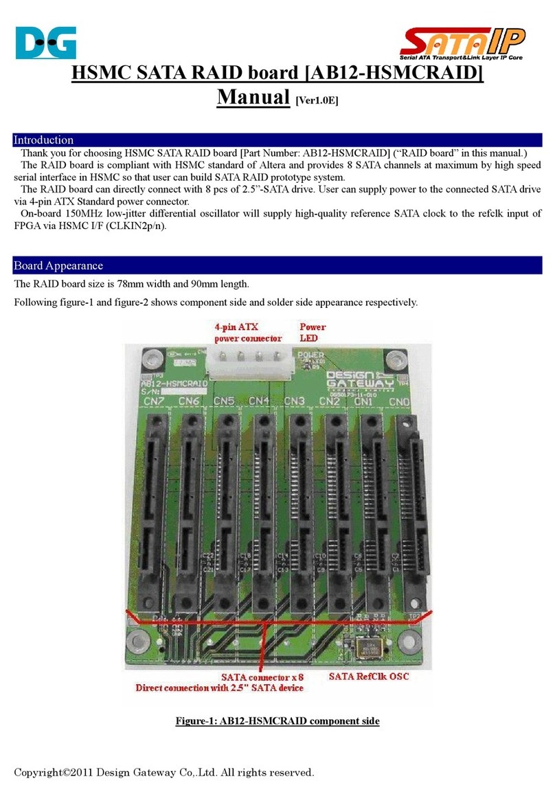
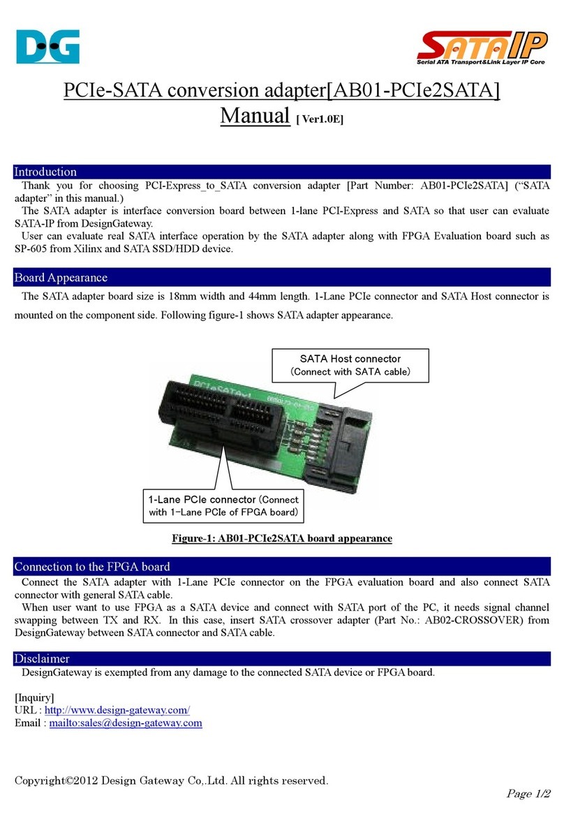
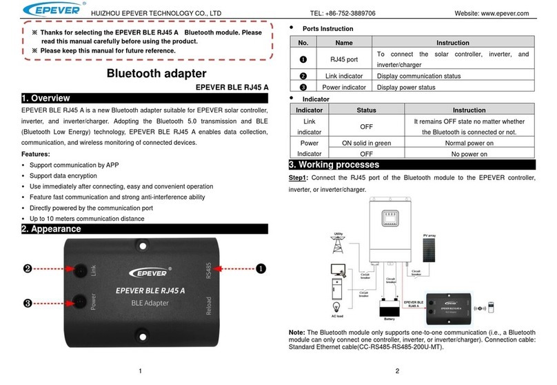
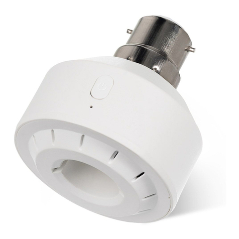
DG AB19-M2PCI User manual

Copyright©2023 Design Gateway Co,.Ltd. All rights reserved.
Page 1/
M.2-PCIe adapter board [AB19-M2PCI]
Manual [ Rev. 1.0E]
Introduction
Thank you for choosing M.2 – PCIe conversion adapter board [Part Number: AB19-M2PCI] (“adapter
board” in this manual). This adapter board converts 16-lane PCI Express interface to four 4-lane PCI standard
M.2 interfaces. This adapter can be applied to standard Intel or Xilinx FPGA evaluation board so that user can
evaluate NVMe series IP-Core operation and can use for prototype development platform.
Four M.2 connectors are mounted on the component side of the adapter board to accommodate up to four
M.2 SSDs up to 2280 size. On the solder side, 16-lane PCIe (PCI Express) connectors are mounted, and
lanes 0-3/4-7/8-11/12-15 connect to the SSDs mounted on CN1/CN2/CN3/CN4, respectively.
The adapter includes a low-jitter clock generator and reset circuitry to provide clock and reset signals to
PCIe and M.2 SSDs. Power for the adapter and M.2 SSDs is provided by a standard 6-pin type PCI Express
auxiliary power supply. A 12V cooling fan connector is provided for use with fan coolers or other devices that
require forced cooling of the SSD.
The product comes with a supporting accessory to prevent this adapter from tilting when connected to the
FPGA board's PCIe, and can be adjusted with wing nuts to ensure that the adapter is always in the correct
vertical orientation.
This adapter and supporting accessories connected to the FPGA board are shown in Figure 1 below.
Figure-1: AB19-M2PCIe adapter with supporting accessory
The features of this adapter are shown below.
Expansion adapter board for M.2 SSD with 16-Lane PCI Express support
Normal access between FPGA and M.2 SSD in PCIe Gen5, confirmed in actual device operation
Up to four M.2 SSDs up to 2280 size can be installed simultaneously
Power is supplied at +12V from a standard external 6-pin PCIe auxiliary power supply
DC/DC converter inside the adapter generates up to 20A of +3.3V power
Power supply to the adapter and M.2 SSD can be controlled ON/OFF with a switch
Four 12V connectors for SSD cooling fans
PCIe standard 100MHz low-jitter clock source mounted on the adapter
Supplies 100MHz differential clock signals of the same phase to PCIe and four SSDs
Reset is selectable between PCIe-SSD direct connection and reset output on the adapter board via
jumper socket
AB19-M2PCI
Adapter
Supporting
Accessory
FPGA board
Adjustable
wing nut
4 x M.2 SSD
Connect aux. PCIe
6pin power cable

Copyright©2023 Design Gateway Co,.Ltd. All rights reserved.
Page 2/
Adapter outline
The board size of this adapter is 125 mm wide and 115 mm long. The component side and the solder side
of the board are shown in Figure 2 and Figure 3 below, respectively. The distance between adjacent SSDs is
27mm, so please pay attention to the width size when attaching a heat sink for SSD cooling.
Figure-2: adapter board component side
Figure-3: adapter board solder side
Reset setting
Jumper header
Reset switch
Power switch
Power LED
6pin aux. PCIe
power conn.
16Lane PCIe socket
Fan power conn. x 4
Cut-hole to fix support accessory
by M3 screw (inner 2 holes)
27mm

Copyright©2023 Design Gateway Co,.Ltd. All rights reserved.
Page 3/
Supporting Accessory
This product includes following accessories.
[Accessories].
support board: 1pcs
wing nut: 2 pcs
M3 spacer (male/female): 2 pcs.
M3 screw: 2 pcs.
Assemble the support accessory to the adapter board as shown in Figure 4. When the adapter board is
connected to the FPGA board, use wing nut so that adapter is properly oriented vertically. The spacer should
be screwed on from the solder side of the adapter using M3 screws through the inner side holes.
Figure-4: adapter with supporting board assembly
Fix spacer by M3 screw from
solder side of the adapter
Adjustable wing nut
on male thread side
30mm length male-female type M3 spacer

Copyright©2023 Design Gateway Co,.Ltd. All rights reserved.
Page 4/
Power Supply
This adapter power is supplied by +12V from a 6-pin type PCIe auxiliary power supply as shown in Figure 5.
The power switch controls the power supply to the adapter and the installed SSD. The power-on status can
be checked with the LED next to the power switch.
The +12V power supply is used to generate a +3.3V power supply with a DC/DC converter inside the
adapter, which has a maximum supply capacity of 20A. The current consumption of the adapter itself is as low
as 100mA, so even when four M.2 SSDs are installed, the power supply can supply approximately 5A per
SSD.
Figure-5: Power switch, PCIe auxiliary power supply, and its pin assignment
Connector for Cooling Fan
When continuously operating the latest high-speed SSDs, it is necessary to cool the heated SSDs using a
heat sink with a fan, etc. This adapter is equipped with four fan connectors that supply +12V for cooling fans
at the positions shown in Figure 6. The pin assignment of each connector is as follows.
[Connector for cooling fan J2-J5 pin assignment]
Pin#1: GND
Pin#2: +12V
Pin#3: (No Connect)
Figure-6: Four connectors for Cooling Fan
Pin#1
GND
Pin#2
+12V
Pin#3
(N.C)

Copyright©2023 Design Gateway Co,.Ltd. All rights reserved.
Page 5/
Access Indicator LED
There is an SSD access LED near each M.2 connector as shown in Figure 7, which emits light when the
respective M.2 connector pin 10 (DAS/DSS signal) is at a Low level.
Figure-7: Access Indicator LED for each SSD
Clock circuit
The adapter is equipped with a clock generator that complies with the PCI Express Gen5 standard and
provides 100MHz differential clocks in the same phase for all PCIe clock and all 4 channels of M.2 SSDs
system clock. The clock frequency is fixed at 100 MHz and cannot be changed.
Reset circuit
The adapter contains a reset IC that generates reset signals for PCIe and M.2, a reset switch for manually
generating a reset signal, and 2x2 jumper headers for selecting each reset system.
The reset IC constantly monitors the voltage level of the +3.3V power supply and outputs a low active reset
signal when the voltage level falls below approximately 3.0V. It also generates a reset signal pulse of about
100msec when the reset switch is pressed.
The reset signal connection can be set as shown below by inserting a socket into the 2 x 2 4-pin header JP1
shown in Figure 8. (The factory default socket settings are the connections between 1-3 and between 2-4 as
shown in Figure 8.)
Short between 1 and 3: Connects the reset IC output to the reset of all 4 M.2 SSDs.
Short between 2 and 4: Connects the reset IC output to the PCI Express reset
Short between 1-2: Connects PCI Express reset to all 4 M.2 SSD resets.
Figure-8: Reset switch (SW1) and pin header (JP1) for reset connection settings

Copyright©2023 Design Gateway Co,.Ltd. All rights reserved.
Page 6/
Connection between PCIe and each M.2 SSD
The connection between each lane of the PCIe socket and the four M.2 SSDs attached to CN1-CN4 in this
adapter is as follows
PCIe Lane# (signal direction) PCIe signal name PCIe Pin# M.2 Conn. M.2 Pin#
Lane0 Tx (FPGA->PCIe->M.2) PERp0/PERn0 A16/A17 CN1 49/47
Lane0 Rx (FPGA<-PCIe<-M.2) PETp0/PETn0 B14/B15 CN1 43/41
Lane1 Tx (FPGA->PCIe->M.2) PERp1/PERn1 A21/A22 CN1 37/35
Lane1 Rx (FPGA<-PCIe<-M.2) PETp1/PETn1 B19/B20 CN1 31/29
Lane2 Tx (FPGA->PCIe->M.2) PERp2/PERn2 A25/A16 CN1 25/23
Lane2 Rx (FPGA<-PCIe<-M.2) PETp2/PETn2 B23/B24 CN1 19/17
Lane3 Tx (FPGA->PCIe->M.2) PERp3/PERn3 A29/A30 CN1 13/11
Lane3 Rx (FPGA<-PCIe<-M.2) PETp3/PETn3 B27/B28 CN1 7/5
Lane4 Tx (FPGA->PCIe->M.2) PERp4/PERn4 B33/B34 CN2 49/47
Lane4 Rx (FPGA<-PCIe<-M.2) PETp4/PETn4 A35/A36 CN2 43/41
Lane5 Tx (FPGA->PCIe->M.2) PERp5/PERn5 B37/B38 CN2 37/35
Lane5 Rx (FPGA<-PCIe<-M.2) PETp5/PETn5 A39/A40 CN2 31/29
Lane6 Tx (FPGA->PCIe->M.2) PERp6/PERn6 B41/B42 CN2 25/23
Lane6 Rx (FPGA<-PCIe<-M.2) PETp6/PETn6 A43/A44 CN2 19/17
Lane7 Tx (FPGA->PCIe->M.2) PERp7/PERn7 B45/B46 CN2 13/11
Lane7 Rx (FPGA<-PCIe<-M.2) PETp7/PETn7 A47/A48 CN2 7/5
Lane8 Tx (FPGA->PCIe->M.2) PERp8/PERn8 B50/B51 CN3 49/47
Lane8 Rx (FPGA<-PCIe<-M.2) PETp8/PETn8 A52/A53 CN3 43/41
Lane9 Tx (FPGA->PCIe->M.2) PERp9/PERn9 B54/B55 CN3 37/35
Lane9 Rx (FPGA<-PCIe<-M.2) PETp9/PETn9 A56/A57 CN3 31/29
Lane10 Tx (FPGA->PCIe->M.2) PERp10/PERn10 B58/B59 CN3 25/23
Lane10 Rx (FPGA<-PCIe<-M.2)
PETp10/PETn10 A60/A61 CN3 19/17
Lane11 Tx (FPGA->PCIe->M.2) PERp11/PERn11 B62/B63 CN3 13/11
Lane11 Rx (FPGA<-PCIe<-M.2) PETp11/PETn11 A64/A65 CN3 7/5
Lane12 Tx (FPGA->PCIe->M.2) PERp12/PERn12 B66/B67 CN4 49/47
Lane12 Rx (FPGA<-PCIe<-M.2)
PETp12/PETn12 A68/A69 CN4 43/41
Lane13 Tx (FPGA->PCIe->M.2) PERp13/PERn13 B70/B71 CN4 37/35
Lane13 Rx (FPGA<-PCIe<-M.2)
PETp13/PETn13 A72/A73 CN4 31/29
Lane14 Tx (FPGA->PCIe->M.2) PERp14/PERn14 B74/B75 CN4 25/23
Lane14 Rx (FPGA<-PCIe<-M.2)
PETp14/PETn14 A76/A77 CN4 19/17
Lane15 Tx (FPGA->PCIe->M.2) PERp15/PERn15 B78/B79 CN4 13/11
Lane15 Rx (FPGA<-PCIe<-M.2)
PETp15/PETn15 A80/A81 CN4 7/5
Table-1: Connection between each PCIe lane and four M.2 SSDs

Copyright©2023 Design Gateway Co,.Ltd. All rights reserved.
Page /
Disclaimer
Any damage to the FPGA evaluation board or SSD device caused by misuse of this adapter will be
exempted from any and all liability. In addition, this adapter board is for evaluation purposes only, and may
not operate properly depending on the characteristics of the FPGA evaluation board or the SSD device to
which it is connected, but this is an exemption from liability except for manufacturing defects in the adapter
board.
[Contact]
URL : http://www.dgway.com
Email : info@dgway.com
Revision History
Revision Date Description
1.0E Apr-15th-2023 English manual first release
Table of contents
Other DG Adapter manuals
