7 ENGLISH( )
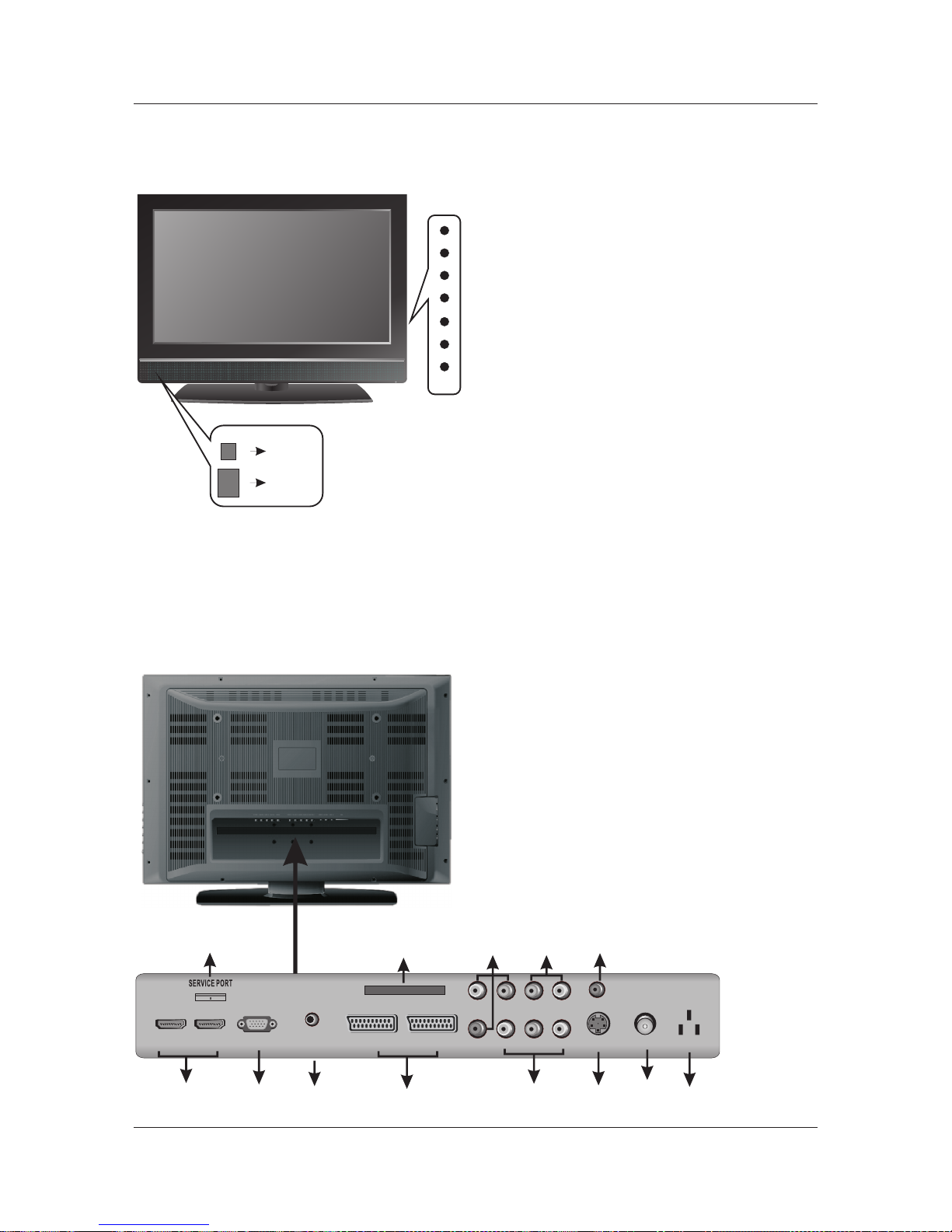
4 Front Controls and Rear Connections.
1. Power. Switches Tv from Standby to operate
and back to standby.
2. V+/V- Increases and Decreases volume level..
3. P+/P-. Selects TV channels up and down.
4. Menu. Selects operational menu’s.
5. Source. Selects input source.
6 Led Indicator. Displays status of Tv. Red in .
standby, Green in operation.
7. IR. Infrared receiving window for Remote
Control.
RF IN
S-VIDEO
HDMI2 PC
AUDIO
PC IN
Pb
Y
Pr
VIDEO
HDMI1
L
R
L
R
SCART1 SCART2
4
3
21
11 12
5 6
13
7
8
AC IN
CI PORT
109
13.COAX: Connect the audio
amplifier.
MENU
POWER
SOURCE
V-
V+
P-
P+
IR
ON/OFF
LED
Back View and Control Connections
Front View
COAX
5.
VCR.
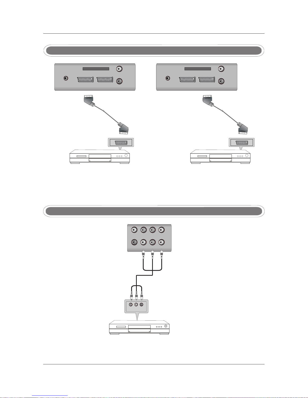
VIDEO: Connect the Video output jack of DVD or
7. RF IN: Connect the antenna
and HD DVB-T digital TV signal input.
. It supports analog
1. HDMI: Connect the HDMI output jack of DVD.
2. PC IN: Connect the PC-RGB output jack of PC .
11. YPbPr: Connect the YPbPr output jack of DVD or VCR.
6. S-VIDEO: Connect the S-VIDEO output jack of
DVD or VCR .
8. AC IN: Main power input.
9. SERVICE Port: For factory uses only.
10. CI Port: Connect the CI CARD.
3. PC AUDIO: Connect the Audio output jack of PC.
4. SCART: Connect the SCART output jack of VCR or DVD.
12. Audio L/R Y Pb Pr Audio input: