DGS 101 Instruction Manual

TECHNOLOGIES
Technical Sheet
ref C1540 J
GDS 101
SINGLE POINT GAS ALARM
Operation
A fixed single point alarm unit that meets the requirements for continuous economic and reliable monitoring of gas levels in a
wide range of environments from commercial premises through to heavy industrial applications that may require hazardous
area sensing. The GDS101 may be utilised as a standalone unit or as an addressable sensor forming part of the GDS Combi
CANbus addressable network system and therefore offering the features of our most advanced system.
Typical monitor locations are – public buildings, boiler plant rooms, swimming pools, water treatment works, H&V control
systems, manufacturing and process plants.
Installation
CONTROL UNIT: The control unit should be mounted in a position which is
accessible and in the field of vision.
Mains should be from a fused supply.
SENSORS: The positioning of sensors depends upon the type of gas to be
monitored and its density with respect to air.
HEAVY GASES (LPG, Propane, Butane, Refrigerant Gases) – locate at 15
to 20 cm from the floor.
LIGHTER GASES (Methane, Natural Gas, Town Gas) –
locate at 5 to 10cm from the ceiling.
CARBON MONOXIDE – locate at 1.5 metres above floor level.
All equipment should be mounted away from direct heat and in
accordance with its IP rating.
Initial Set–up Procedure
Having terminated all cables switch on the power and wait for the 1 minute
stabilisation period to complete, this is indicated by the power and inhibit
indicator changing from flashing to a steady state, a reduced power mode
feature is activated one hour following any operator activity, this state is
indicated by a screen power reduction of approximately 50%, pressing
any button will return the screen to full display.
The alarm panel may have been supplied without a sensor and a customer
supplied device is to be used, in this case the following adjustments should
be carried out. Adjust jumpers as follows:
For 24DC (+ sig –) 4~20mA sensor devices connect jumpers
J5/11 Position A, J12 Off, J14 link B.
For catalytic sensors (W Y P) J5/11 Position B, J12 On, J14 Link A.
(Caution reset link J14 to position A before connecting the sensor
as damage will occur requiring sensor replacement).
Sensor supply may be measured between the two sensor voltage test pins,
adjust as required using the sensor supply adjustment potentiometer. See
sensor cell supply table.
Test pins TP6/TP7 may be used to check 4~20mA sensor input signals 4mV
= 4mA.
Measuring across TP8/TP9 will allow the 4~20mA output signal to be
checked 4mV = 4mA. Output for pellistor (flammable) can be adjusted
using 4+20mA pots.
Changes to gas type and range can be made by connecting GDS RS232
pod to J3 and using a PC running hyper terminal at 4800 baud.
The Hyper Terminal output screen shows continuous data output/
commands and allows input from the PC keyboard pressing ‘C’ enters
calibration mode, press ‘G’ to change the gas type to match the cell being
used. Note – the range of the new gas has a default value but can be
adjusted by pressing ‘R’.
For catalytic sensors course zero adjustment is achieved by turning the zero
potentiometer (10 turn) until the zero LED just turns off.
Access to the Menu
The GDS101 is supplied with factory set default settings which may be
re-adjusted from the front screen and push buttons:
Press 2 to access the menu followed by 231, menu entry will be at level 5
(Exit), pressing 1 or 3 will enable travel through the sub menus 1–9 and
adjustment of settings, pressing 2 enables access into each sub menu and
on completion pressing 2 will confirm your selection and move to the next
setting.
1. Zero/Span – In clean air Zero display – apply test gas at the peak
reading and adjust the span.
2. Alarm Levels – 3 alarm levels. Pressing 1+3 together will cycle through
rising and falling alarms and latched (L) or unlatched (U) (auto reset)
relays in following order
() L, ( ) U, ( ) U, ( ) L. Default setting latched.
3. Alarm Delay – Time to alarm in seconds
(default setting 2 seconds) maximum 255 seconds.
4. Inhibit Alarm – Isolate alarm functions – maintenance and test periods.
Second part of this menu allows YES/NO selection of sounder alert for
alarm A1.
5. Exit Press 2 – Entry and Exit point of menu.
6. L.C.D Brightness – Adjustment of display brightness.
7. L.E.D/Relay Test – Turns indicators and relays ON.
8. Auto Zero – Use only when very low alarm levels are required
(<10% of scale).
9. Sensor Address – Used when connecting to a GDS
Combi system.
A. 4~20mA output adjust (Tox/O2only). Pressing 1 or 3 will allow for
output to be adjusted to 4mA and 20mA as measured on test pins 8+9.
B. To set A1 alarm relay to become a global sounder relay with a 10min
time delay after alarm condition ends. Press 1 to active or press 3 to
deactivate.
C. To delay relay deactivation after alarm condition has ceased, press
2 to cycle through alarms A1,A2 and A3. when the required alarm is
displayed press 1 to increase the delay and 3 to decrease the delay.
D. Allows relay A3 to change from alarm relay to valve timer central relay
E. Relay on time, minimum 2 minutes maximum 200 mins.
F. Relay off time, minimum 2 minutes maximum 200 mins.
GDS TECHNOLOGIES LTD |FUSION POINT |ASH LANE |GARFORTH |LEEDS |LS25 2GA |UK www.gds-technologies.co.uk

TECHNOLOGIES
GDS TECHNOLOGIES LTD |FUSION POINT |ASH LANE |GARFORTH |LEEDS |LS25 2GA |UK www.gds-technologies.co.uk
This document is not contractual and the equipment specification may be modified at any time without prior notice.
Technical Sheet
ref C1540 J
Mains Version
230/115v AC 50/60 Hz
DC Version 24v DC ± 15%
Power 4w
Outputs
Alarms 1, 2, 3 relays – S.P.C.O. ND (NE option)
Fault Relay – S.P.C.O. ND (NE option)
normaly latched (unlatched option)
Relay contacts rated 3A/230v AC
CANbus – see Combi alarm system
4~20mA analogue output
Sensor Cell Supply Table
Indicators
Power Green L.E.D
Alarms 1, 2, 3 Red L.E.D’s
Fault Amber L.E.D
Display 2 line alpha–numeric
Audible Alarm
Gas/Fault mutable: 85dB@10cm
Environmental
Operating temperature: 15 to +50°C
Storage temperature: 5 to +55°C
Humidity 5–95% RH non condensing
Protection IP65
Sensor Cable
3 core 1.5mm screened →1.5km
SPECIFICATION
4–20
OV
Lo
Hi
24V
NO C
AL3
NC NO C
NCNO C
AL2
NCNO C
AL1
NC
W
+
Y
sig
P
–
SENSOR FAULT
+ –
4–20mA
Output
PC comms via
hyperterminal
Sensor
Voltage
test pins
Zero LED
4mA
J28
20mA
Zero
Gain
J3
J29
J 11
J18 J17 J16
J15
J19
J1
TP3
A B
A
B
A
B
TP11
TP12
TP6TP7
TP13
TP8 TP9 TP2
TP4
TP1
Contrast
J6
J20
J5
J4 J7
J 12
J 13 J 14
J8
J9
x fault
Inhibit Ov 24v J1 CANbus – EOL – see Combi
J4/7 For Semiconductor sensors
J5/11 Sensor (B–catalytic A–4~20mA)
J6/20 Sink/Source 4~20mA output
J8 Gain – factory set
J9 Normally fitted 4~20mA out
J12 Bridge fault enable fit for catalytic sensor
J13 See J8
J14 Sensor supply selector
A for catalytic sensor
B for 4~20mA sensor
J15 Sounder mute
J16 N/E – A3 relay link on
J17 N/E – A2 relay link on
J18 N/E – A1 relay link on
J19 N/E – fault relay link on
J28 Reset processor
J29 Address change enable – see Combi
C1529
A
B
4~20mA In
Sensor
supply
adjust
4~20mA
Output
CAT300A 2v/300mA
CAT170A 2v/175mA
SEM–1 5v/170mA
SEM–1 4v/170mA Ammonia
GDS PRIME 4v/70mA
F6–170 2v/175mA
CAT335C 2.5v/335mA
THE300A 2v/300mA
SS10 2v/175mA
CAT335A 2.5v/335mA
CAT335B 2.5v/335mA
CAT100A 2v/100mA
3 wire
GDS 101 Sensor
+24
0v
4~20mA
+ s
Y PW
–
+24
Hi
Lo
0v
4~20mA
2 wire
GDS 101 Sensor
+24
0v
4~20mA
+ s
Y PW
–
Popular Security System manuals by other brands

Concoa
Concoa Advantium 1 Plus Installation and operating instructions

Avitech
Avitech Rainier-4a user manual
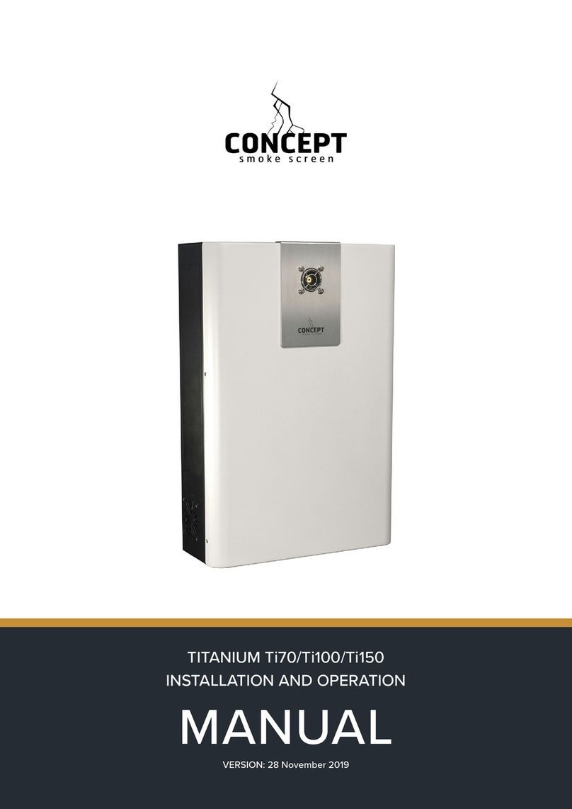
Concept Smoke Screen
Concept Smoke Screen TITANIUM Ti70 Installation and operation manual
Radio Shack
Radio Shack Self-Stick Door/Window Alarm owner's manual

Paso
Paso PAW5500-VES Series quick start guide
Vestil
Vestil BOL-G-24-3.5 Use and maintenance instructions
Bosch
Bosch FMC-210-DM-G-B installation instructions
Alderon Industries
Alderon Industries Versa'larm VA02A Operation, maintenance and installation manual
Trigon
Trigon 301A operating instructions
Imrita
Imrita IMT-P-ZL6 installation instructions

Viper
Viper 3606V owner's guide
PNI
PNI SafeHouse HS650 user manual
