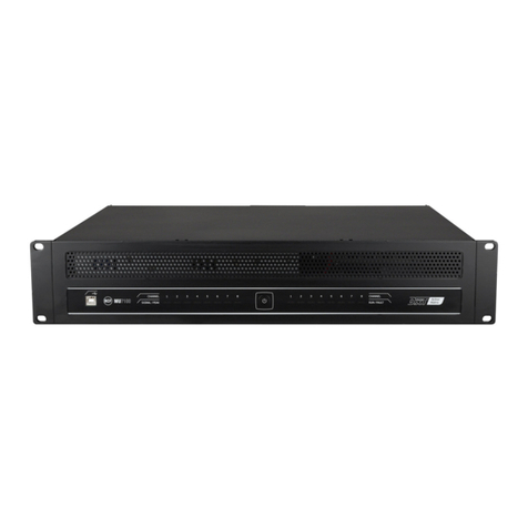
RCF MU 7100EN User manual

OWNER’S MANUAL
MANUALE UTENTE
MU 7100EN MKII
DXT 7000EN VOICE ALARM SYSTEM AMPLIFIED MASTER UNIT


3
CONTENTS
ENGLISH
CONTENTS ..................................................................................................................................................................................... 3
SAFETY PRECAUTIONS AND GENERAL INFORMATION .................................................................................................................... 4
DESCRIPTION ................................................................................................................................................................................. 6
FRONT PANEL ................................................................................................................................................................................ 7
REAR PANEL .................................................................................................................................................................................. 8
OTHER SYSTEM COMPONENTS..................................................................................................................................................... 10
MU 7100EN MKII OPERATION AND USE ....................................................................................................................................... 12
MAINTENANCE ............................................................................................................................................................................ 22
ITALIANO
AVVERTENZE PER LA SICUREZZA ................................................................................................................................................. 23
DESCRIZIONE ............................................................................................................................................................................... 26
PANNELLO FRONTALE .................................................................................................................................................................. 27
PANNELLO POSTERIORE ............................................................................................................................................................... 28
ALTRI COMPONENTI DEL SISTEMA ............................................................................................................................................... 30
MU 7100EN MKII FUNZIONAMENTO ED USO ............................................................................................................................ 32
MANUTENZIONE .......................................................................................................................................................................... 42
DIMENSIONS ................................................................................................................................................................................ 43
SPECIFICATIONS ........................................................................................................................................................................... 44

4
SAFETY PRECAUTIONS AND GENERAL INFORMATION
The symbols used in this document give notice of important
operating instructions and warnings which must be strictly
followed.
CAUTION
Important operating
instructions: explains hazards
that could damage a product,
including data loss.
WARNING
Important advice concerning the
use of dangerous voltages and
the potential risk of electric
shock, personal injury or death.
IMPORTANT
NOTES
Helpful and relevant
information about the topic.
SUPPORTS,
TROLLEYS
AND CARTS
Information about the use of
supports, trolleys and carts.
Reminds to move with extreme
caution and never tilt.
WASTE
DISPOSAL
This symbol indicates that this
product should not be disposed
with your household waste,
according to the WEEE directive
(2012/19/EU) and your national
law.
IMPORTANT NOTES
This manual contains important information about the correct
and safe use of the device. Before connecting and using this
product, please read this instruction manual carefully and
keep it on hand for future reference. The manual is to be
considered an integral part of this product and must
accompany it when it changes ownership as a reference for
correct installation and use as well as for the safety
precautions. RCF S.p.A. will not assume any responsibility for
the incorrect installation and / or use of this product.
SAFETY PRECAUTIONS
1. All the precautions, in particular the safety ones, must be
read with special attention, as they provide important
information.
2. Power supply from mains
a. The mains voltage is sufficiently high to involve a risk of
electrocution; install and connect this product before
plugging it in.
b. Before powering up, make sure that all the connections
have been made correctly and the voltage of your mains
corresponds to the voltage shown on the rating plate on
the unit, if not, please contact your RCF dealer.
c. The metallic parts of the unit are earthed through the
power cable. An apparatus with CLASS I construction shall
be connected to a mains socket outlet with a protective
earthing connection.
d. Protect the power cable from damage; make sure it is
positioned in a way that it cannot be stepped on or
crushed by objects.
e. To prevent the risk of electric shock, never open this
product: there are no parts inside that the user needs to
access.
f. Be careful: in the case of a product supplied by
manufacturer only with POWERCON connectors and
without a power cord, jointly to POWERCON connectors
type NAC3FCA (power-in) and NAC3FCB (power-out), the
following power cords compliant to national standard
shall be used:
-EU: cord type H05VV-F 3G 3x2.5 mm2 - Standard IEC
60227-1
-JP: cord type VCTF 3x2 mm2; 15Amp/120V~ -
Standard JIS C3306
-US: cord type SJT/SJTO 3x14 AWG; 15Amp/125V~ -
Standard ANSI/UL 62
3. Make sure that no objects or liquids can get into this
product, as this may cause a short circuit. This apparatus
shall not be exposed to dripping or splashing. No objects
filled with liquid, such as vases, shall be placed on this
apparatus. No naked sources (such as lighted candles)
should be placed on this apparatus.
4. Never attempt to carry out any operations, modifications
or repairs that are not expressly described in this manual.
Contact your authorized service centre or qualified
personnel should any of the following occur:
-The product does not function (or functions in an
anomalous way).
-The power cable has been damaged.
-Objects or liquids have got in the unit.
-The product has been subject to a heavy impact.
5. If this product is not used for a long period, disconnect the
power cable.
6. If this product begins emitting any strange odours or
smoke, switch it off immediately and disconnect the power
cable.
7. Do not connect this product to any equipment or
accessories not foreseen.
For suspended installation, only use the dedicated anchoring
points and do not try to hang this product by using elements
that are unsuitable or not specific for this purpose. Also check
the suitability of the support surface to which the product is
anchored (wall, ceiling, structure, etc.), and the components
used for attachment (screw anchors, screws, brackets not
supplied by RCF etc.), which must guarantee the security of
the system / installation over time, also considering, for
example, the mechanical vibrations normally generated by
transducers. To prevent the risk of falling equipment, do not

5
stack multiple units of this product unless this possibility is
specified in the user manual.
8. RCF S.p.A. trongly recommend thi product i
only in talled by profe ional qualified in taller
(or peciali ed firm ) who can en ure correct
in tallation and certify it according to the
regulation in force. The entire audio y tem mu t
comply with the current tandard and regulation
regarding electrical y tem .
9. Supports, trolleys and carts.
The equipment should be only used on supports,
trolleys and carts, where necessary, that are recommended
by the manufacturer. The equipment / support / trolley /
cart assembly must be moved with extreme caution.
Sudden stops, excessive pushing force and uneven floors
may cause the assembly to overturn. Never tilt the
assembly.
10.There are numerous mechanical and electrical factors to
be considered when installing a professional audio system
(in addition to those which are strictly acoustic, such as
sound pressure, angles of coverage, frequency response,
etc.).
11.Hearing loss. Exposure to high sound levels can cause
permanent hearing loss. The acoustic pressure level that
leads to hearing loss is different from person to person and
depends on the duration of exposure. To prevent
potentially dangerous exposure to high levels of acoustic
pressure, anyone who is exposed to these levels should
use adequate protection devices. When a transducer
capable of producing high sound levels is being used, it is
therefore necessary to wear ear plugs or protective
earphones. See the manual technical specifications to
know the maximum sound pressure level.
OPERATING PRECAUTIONS
-Place this product far from any heat sources and always
ensure an adequate air circulation around it.
-Do not overload this product for a long time.
-Never force the control elements (keys, knobs, etc.).
-Do not use solvents, alcohol, benzene or other volatile
substances for cleaning the external parts of this product.
IMPORTANT NOTES
To prevent the occurrence of noise on line signal cables, use
screened cables only and avoid putting them close to:
-Equipment that produce high-inten ity
electromagnetic field
-Power cable
-Loud peaker line
WARNING! CAUTION! To prevent
the ri k of fire or electric hock, never expo e thi
product to rain or humidity.
WARNING! To prevent electric hock
hazard, do not connect to main power upply
while grille i removed.
WARNING! to reduce the ri k of electric
hock, do not di a emble thi product unle you
are qualified. Refer ervicing to qualified ervice
per onnel.
CORRECT DISPOSAL OF THIS PRODUCT
This product should be handed over to an authorized
collection site for recycling waste electrical and electronic
equipment (EEE). Improper handling of this type of waste
could have a possible negative impact on the environment and
human health due to potentially hazardous substances that
are generally associated with EEE. At the same time, your
cooperation in the correct disposal of this product will
contribute to the effective usage of natural resources. For
more information about where you can drop off your waste
equipment for recycling, please contact your local city office,
waste authority or your household waste disposal service.
CARE AND MAINTENANCE
To ensure a long-life service, this product should be used
following these advices:
-If the product is intended to be set up outdoors, be sure it
is under cover and protected to rain and moisture.
-If the product needs to be used in a cold environment,
slowly warm up the voice coils by sending a low-level
signal for about 15 minutes before sending high-power
signals.
-Always use a dry cloth to clean the exterior surfaces of the
speaker and always do it when the power is turned off.
CAUTION: to avoid damaging the exterior
fini he do not u e cleaning olvent or abra ive .
WARNING! CAUTION! For powered
peaker , do cleaning only when the power i
turned off.

6
DESCRIPTION
MU 7100EN MKII is the main unit of the innovative RCF DXT 7000EN system, which has been designed to fulfil all requirements of
EN 54-16 and EN 60849 standards.
RCF DXT 7000EN sound system is suitable for different purposes, such as evacuation, paging and background music.
Typical targets are halls, schools, shopping centres, hospital, railway stations, hotels, etc.
Up to 64 MU 7100EN MKII can be linked together to get an extended system including many paging stations and up to 512 speaker
lines / paging zones.
The main unit can play all necessary evacuation and alarm messages previously stored to its digital memory.
It is possible to control, manage and monitor MU 7100EN MKII over TCP/IP based Local Area Network.
The 8 digital internal amplifiers are reliable and their efficiency is excellent (> 90%), that means less heat dissipation and smaller
capacity requirement for unbreakable power supply sources (UPS) and batteries used in sound evacuation systems.
The whole signal path from paging microphones to speaker lines is completely and automatically monitored against faults.
All properties and functions of the system are specified with Windows® based DXT 7000EN configuration software and loaded to the
master unit through either LAN network or its USB port.
MAIN FEATURES
•
In compliance with EN 54-16 and EN 60849 standards (voice evacuation system)
•
Link of up to 64 MU 7100EN MKII main units (up to 512 paging zones)
•
8 independent 80W RMS (on a 8-ohm load) amplifiers
•
7-input x 8-output digital audio matrix
•
7 analogue audio inputs, mic/line level
•
8 I²S digital audio inputs (two ports)
•
Built-in message player
•
Messages stored on USB flash drives
•
Internal timer
•
Phantom voltage for electret microphones
•
8 control (logic) inputs
•
8 control (logic) outputs
•
System connection through 'System Bus' and 'Local Bus' (or redundant system bus)
•
Wiring with CAT5/6/7 cable
•
Internal digital signal processor (DSP)
•
Volume and source controls on user panels

7
FRONT PANEL
[1] USB (B) port for PC link. Used for system programming, monitoring and administration.
[2] Input signal indicators (one per channel). A blue LED indicates the audio signal presence in the respective channel, a red LED
instead indicates a too high input signal level.
BUS indicator LED is active if the spare master change-over feature is activated. Blue indicates that the master unit is commanding
the system, red instead indicates that the spare master is active.
[3] Status indicator: in normal operation (without any system faults), the four blue corner LEDs are steady lit. Dim blue light indicates
that the device is powered but not in its active state.
When the system is in stand-by mode, the blue LEDs are blinking.
When the system is fault monitored and one or more faults are detected, the blue LEDs are turned off and four orange LEDs start
blinking.
When one or more system faults have been detected, orange LEDs are steady lit and the blue ones are blinking.
When all system faults are cleared, orange LEDs are turned off.
Faults can be cleared through paging consoles having proper rights or alternatively by using a PC connected to a master unit. The
triggering of the control input function 'No monitoring' also clears faults. All faults (but the system fault) are cleared automatically if
the fault cause disappears.

8
[4] Amplifier output / speaker line fault indicators.
Each blue LED indicates the audio signal presence (or monitoring pilot tone) in its respective speaker line. Note: the indicator operation
has been made slow intentionally; in case of signal absence, a blue LED may still glow for several seconds.
If the amplifier and loud peaker line monitoring i in u e, a po ible fault in any amplifier or peaker line i indicated
by an orange LED.
If no audio signals are present on outputs, amplifier or speaker line monitoring sequence can be seen by active blue LED running
slowly channel by channel.
[5] Top cover fan. There are two temperature-controlled fans inside the unit, one on the back and another one placed on the top
cover.
At least 25 mm free space must be left above each MU 7100EN MKII unit to ensure proper cooling.
REAR PANEL
[1] IEC connector for power cord (to be connected to a mains earthed electric socket only).
[2] Fuses: 2 pcs. of T3.15A (5x20mm). Always use suitable fuses only. Before changing a fuse, the power cord must be detached from
the mains socket.
[3] RS-232 serial port for service purpose.

9
[4] Output connectors for either loudspeakers or a LT 7208EN MKII 'line transfer unit'. Connectors are removable screw terminal
strips, max. wire section is 2.5 mm². Minimum load impedance is 8 Ω.
[5] I2S digital audio inputs (two connectors: CH 1-4 and CH 5-8).
[6] 24 V power supply output, max. 1 A. This output can be linked to LT 7208EN MKII power supply input.
[7] Dual 48 V dc input (2 x 7 A) for secondary power supply (batteries / power supply units).
[8] LAN connector (Ethernet).
[9] System bus override audio output (0 dB) with volume control and relay contacts.
[10] Local bus override audio output (0 dB) and volume control and relay contacts.
[11] CTRL LT 7208: control output for LT 7208EN MKII 'line transfer unit'.
[12] Analogue audio input 1 - 7 connectors.
Note: Audio input +48 V dc Phantom on/off dip-switches are on the lateral side [21].
[13] Gain trimmers for analogue audio inputs 1-7.
Input sensitivity can be adjusted from 45 dBu to +6 dBu.
[14] 8 DIP-switches for digital address setting of each MU 7100EN MKII.
[15] Connector with 8 control (logic) inputs that can be activated by external dry contacts.
[16] Connector with 8 control (logic) outputs.
[17] USB (A) port for USB flash drives.
[18] LOCAL BUS connector (for DXT 7000EN product family devices and mountings).
[19] SYSTEM BUS connector (for DXT 7000EN product family devices and mountings).
Furthermore, system bus can be used to connect main units together.
[20] LINK system bus connector (second system bus port).
[21] +48 V dc Phantom on/off dip-switches of analogue audio input 1 - 7 [12].

10
OTHER SYSTEM COMPONENTS
LT 7208EN MKII – LINE TRANSFORMER UNIT
FRONT VIEW
REAR VIEW
It turns 8 Ω outputs of MU 7100EN MKII into either 70 V or 100 V (factory setting) constant voltage lines for speakers with
transformers.
Output power alternatives: 8 x 80W, 4 x 160 W and 2 x 320W or any combination from these.
It includes also line specific 24V dc outputs for override relays.
BM 7608DFM – FIREMEN PAGING CONSOLE
•High quality handheld monitored microphone
•8 zone / function buttons
•Audio input (3.5 mm TRS jack socket) for an external
program source
•Connection through CAT5/6/7 cable to local or system bus
•Up to 32 paging consoles linked to the system bus and 8
to the local bus
•Backlit LCD
•Numeric keyboard
•Menu based user interface

11
BM 7624D – PAGING CONSOLE
•Flexible gooseneck with monitored microphone
•24 zone / function buttons
•Audio input (3.5 mm TRS jack socket) for an external
program source
•Connection through CAT5/6/7 cable to local or system bus
•Up to 32 paging consoles linked to the system bus and 8
to the local bus
•Backlit LCD
•Numeric keyboard
•Menu based user interface
AC 7212 – SPARE AMPLIFIER CHANGE-OVER BOARD FOR LT 7208EN MKII
AC 7212 is a board to insert a spare amplifier for 2 outputs of the LT 7208EN MKII unit. Each board has 2 main speaker line inputs,
spare amplifier input and output, 2 relays.
AC 7212 shall be directly connected to a pair of LT 7208EN MKII 70-100 V speaker outputs.
A board can control 2 outputs (in pairs: 1-2, 3-4, 5-6 or 7-8).
The LT 7208EN MKII override voltage output is used to activate the AC 7212 relay in case of the main amplifier is faulty and switch
the spare amplifier output to the respective speaker line.
MT 7308 – UNIVERSAL MONITORING UNIT
MT 7308 universal monitoring unit makes it possible to
integrate external (constant voltage) amplifiers into the
monitored DXT 7000EN voice evacuation system. Any
professional single / multichannel amplifier equipped with a 0 ÷
6 dBu balanced audio input and 70/100 V constant voltage
output(s) can be used. One or two MT 7308 can be linked to
each MU 7100EN MKII main unit. An unit can be used for up to
eight external amplifiers (and its speaker line monitoring).
Max. power for each external amplifier: 500 W.
The eighth amplifier can be set as spare that automatically
replaces a faulty one.

12
EL 7001 – END OF LINE UNIT
'End of line' units need to be added when speaker line
monitoring is required.
A unit shall be installed at the end of each line, near the last
installed speaker.
It is suitable for 70 100 V speaker lines (not necessary for an
8 Ω load).
MU 7100EN MKII OPERATION AND USE
MU 7100EN MKII BLOCK DIAGRAM

13
ANALOGUE AUDIO INPUTS
MU 7100EN MKII has 7 balanced analogue audio inputs for external program sources. Each input has a (tool adjustable) gain control
that allows the connection of either a microphone or line level program source. Adjustment screws are located above each input
connector.
The input connector is a detachable terminal block, of which max. wire section is 1.5 mm².
48 V dc 'Phantom' voltage for electret microphones can be turned on with dip-switches.

14
Input 5 can have VOX priority, input 6 is muted during a higher priority of the local bus paging, input 7 is muted during a higher
priority of the system bus paging.
ROUTING AND AMPLIFIER OUTPUTS
MU 7100EN MKII includes 8 digital amplifiers and signal processing for each output channel.
Low impedance (8 Ω) speakers can be directly connected to the rear SPEAKER outputs [4].
If the system is based on constant voltage lines, the speaker outputs shall be connected to LT 7208EN MKII 'Line Transfer' unit inputs
to get 8 outputs x 80 W at 70 /100 V.
The output line voltage setting (70 / 100 V) is internal and made by changing the output tapping of each transformer (this setting is
to be carried out by an authorized service centre).
Default setting is 100 V.
If the needed loudspeaker line power is more than 80 W, several outputs (in groups made of 2, 3 or 4) can be connected together (in
parallel) by making a 'locked group' to obtain 160 / 240 / 320 W line outputs. The 'locked group' is created by using the configuration
software: the settings of the first amplifier are copied to the other channels of the same group, allowing all group amplifiers to operate
in the same identical way.

15
Example of connection MU 7100EN MKII < > LT 7208EN MKII for 80 / 160 / 320 W lines:
SYSTEM AND LOCAL BUS
'System bus' is a control bus covering the whole system. The system components are monitored through this bus. All MU 7100EN
MKII main units are connected to the system bus, control panels and devices can be connected to either the system bus or a local bus.
The system bus wiring can be made by using CAT5/6/7 cable.
All devices connected are powered through the bus (no external power supplies are needed).
All buses contain also one balanced audio channel.
IMPORTANT: the local bu can be extended (when et in the PC oftware) a a pare / redundant y tem bu .
Main system bus and local bus used as spare bus

16
UNIT DIGITAL ADDRESS
Each MU 7100EN has an individual digital address that is set through the first 7 of the 8
DIP-switches located at the rear panel.
Each digital address must be set before powering the system.
Two or more devices cannot have the same digital address.
Digital address setting through DIP-switches:
ADDRESS DIP-SWITCHES
1 2 3 4 5 6 7
1 2 3 4 5 6 7
1 ON OFF OFF OFF OFF OFF OFF 33 ON OFF OFF OFF OFF ON OFF
2 OFF ON OFF OFF OFF OFF OFF 34 OFF ON OFF OFF OFF ON OFF
3
ON ON
OFF
OFF
OFF
OFF
OFF
35
ON ON
OFF
OFF
OFF
ON
OFF
4
OFF
OFF
ON
OFF
OFF
OFF
OFF
36
OFF
OFF
ON
OFF
OFF
ON
OFF
5 ON OFF ON OFF OFF OFF OFF 37 ON OFF ON OFF OFF ON OFF
6 OFF ON ON OFF OFF OFF OFF 38 OFF ON ON OFF OFF ON OFF
7 ON ON ON OFF OFF OFF OFF 39 ON ON ON OFF OFF ON OFF
8 OFF OFF OFF ON OFF OFF OFF 40 OFF OFF OFF ON OFF ON OFF
9
ON
OFF
OFF
ON
OFF
OFF
OFF
41
ON
OFF
OFF
ON
OFF
ON
OFF
10
OFF
ON
OFF
ON
OFF
OFF
OFF
42
OFF
ON
OFF
ON
OFF
ON
OFF
11 ON ON OFF ON OFF OFF OFF 43 ON ON OFF ON OFF ON OFF
12 OFF OFF ON ON OFF OFF OFF 44 OFF OFF ON ON OFF ON OFF
13 ON OFF ON ON OFF OFF OFF 45 ON OFF ON ON OFF ON OFF
14 OFF ON ON ON OFF OFF OFF 46 OFF ON ON ON OFF ON OFF
15
ON ON ON ON
OFF
OFF
OFF
47
ON ON ON ON
OFF
ON
OFF
16
OFF
OFF
OFF
OFF
ON
OFF
OFF
48
OFF
OFF
OFF
OFF
ON ON
OFF
17 ON OFF OFF OFF ON OFF OFF 49 ON OFF OFF OFF ON ON OFF
18 OFF ON OFF OFF ON OFF OFF 50 OFF ON OFF OFF ON ON OFF
19 ON ON OFF OFF ON OFF OFF 51 ON ON OFF OFF ON ON OFF
20 OFF OFF ON OFF ON OFF OFF 52 OFF OFF ON OFF ON ON OFF
21
ON
OFF
ON
OFF
ON
OFF
OFF
53
ON
OFF
ON
OFF
ON ON
OFF
22
OFF
ON ON
OFF
ON
OFF
OFF
54
OFF
ON ON
OFF
ON ON
OFF
23 ON ON ON OFF ON OFF OFF 55 ON ON ON OFF ON ON OFF
24 OFF OFF OFF ON ON OFF OFF 56 OFF OFF OFF ON ON ON OFF
25 ON OFF OFF ON ON OFF OFF 57 ON OFF OFF ON ON ON OFF
26 OFF ON OFF ON ON OFF OFF 58 OFF ON OFF ON ON ON OFF
27
ON ON
OFF
ON ON
OFF
OFF
59
ON ON
OFF
ON ON ON
OFF
28
OFF
OFF
ON ON ON
OFF
OFF
60
OFF
OFF
ON ON ON ON
OFF
29 ON OFF ON ON ON OFF OFF 61 ON OFF ON ON ON ON OFF
30 OFF ON ON ON ON OFF OFF 62 OFF ON ON ON ON ON OFF
31 ON ON ON ON ON OFF OFF 63 ON ON ON ON ON ON OFF
32 OFF OFF OFF OFF OFF ON OFF 64 OFF OFF OFF OFF OFF OFF ON
Note: the address is only read when turning the system on.

17
The MU 7100EN MKII unit having address 1 is always the 'master' that controls the operation of the whole system. The MU 7100EN
MKII unit having address 2 is a spare 'master': if it cannot be connected to the 'master' unit, it will take the system control.
Note: check all addresses twice before powering the system! An incorrect address would lock the system, which would need to be
rebooted (after setting the right addresses).
CONTROL INPUTS
MU 7100EN is equipped with 8 control (logic) inputs for external dry contacts.
Each control input function can be independently programmed via PC software and activated by either closing or opening contacts.
CONTROL OUTPUTS
MU 7100EN has 8 control (logic) outputs, 'open collector' type, which can directly drive 24 V dc relays. Maximum total relay current
is 300 mA.
Each control output function can be independently programmed via PC software.
RS-232 PORT
(9-PIN D-SUB connector)
This port is for factory service only.
LAN (ETHERNET) PORT
MU 7100EN MKII is equipped with 100 MHz LAN port (TCP/IP) for system configuration, control (Local Bus and System Bus data) and
monitoring.
Each unit has its own (adjustable) system IP address.
USB (A) PORT
A USB flash drive having recorded messages (WAV files that can be played through the system) can be connected to the USB (A) port.
Note: any message that is used in the configuration, but not stored to the internal memory yet, will be automatically loaded after the
first usage (from the USB-memory stick to the internal flash memory).
USB (B) PORT
USB port for PC link (when the LAN port is not used).
When using the DXT 7000EN
configuration software, all system properties can be configured through the 'master' unit. All necessary
data are sent from the 'master' MU 7100EN MKII to all the others and devices connected to both the system bus and local bus.
A USB cable to link the 'master' MU 7100EN MKII unit to a PC is included.
SYSTEM CONFIGURATION
About the system configuration, please refer to the DXT 7000EN software user manual.

18
CONNECTORS
AUDIO INPUTS 1 - 7
Pins:
ground
hot
cold
SYSTEM AND LOCAL BUS OVERRIDE AUDIO OUTPUTS
RJ-11 connector
1 ground
2 audio (+ hot)
3 audio ( cold)
4 relay NC contact
5 relay NO contact
6 relay common contact
LT 7208 CONTROL
RJ-45 connector
1 line 1 open collector control
2 line 2 open collector control
3 line 3 open collector control
4 line 4 open collector control
5 line 5 open collector control
6 line 6 open collector control
7 line 7 open collector control
8 line 8 open collector control
SYSTEM BUS AND LINK (LINKED TOGETHER IN PARALLEL) AND LOCAL BUS
RJ-45 connector
Note: audio and data signals must be always connected as separate twisted pairs.
1 System/Local audio (+ hot)
2 System/Local audio ( cold) (1-2 twisted pair)
3 Audio GND
4 Digital GND
5 +12V
6 +24V
7 Data (A)
8 Data (B) (7-8 twisted pair)

19
CONTROL IN/OUT 1 - 8
Removable 16-pin screw terminal strips. Max. wire section: 2.5 mm².
Control input pin Control output pin
1 Control 1 Control 1 (open collector)
2 +12V +24V
3 Control 2 Control 2 (open collector)
4 +12V +24V
5 Control 3 Control 3 (open collector)
6 +12V +24V
7 Control 4 Control 4 (open collector)
8 +12V +24V
9 Control 5 Control 5 (open collector)
10 +12V +24V
11 Control 6 Control 6 (open collector)
12 +12V +24V
13 Control 7 Control 7 (open collector)
14 +12V +24V
15 Control 8 Control 8 (open collector)
16 +12V +24V
RS-232 PORT
Pins
1 5 GND
2 Rx Data 6
3 Tx Data 7
4 8
LAN PORT (ETHERNET)
RJ45 Type CAT6e port 10/100/100Base-T(X)

20
SPEAKER OUTPUTS 1 - 8
Removable 8-pin screw terminal strips. Max. wire section: 2.5 mm².
Pin (left to right)
1 Channel 1 output +
2 Channel 1 output -
3 Channel 2 output +
4 Channel 2 output -
5 Channel 3 output +
6 Channel 3 output -
7 Channel 4 output +
8 Channel 4 output -
9 Channel 5 output +
10 Channel 5 output -
11 Channel 6 output +
12 Channel 6 output -
13 Channel 7 output +
14 Channel 7 output -
15 Channel 8 output +
16 Channel 8 output -
24 V DC POWER OUTPUT FOR LT 7208EN MKII
Removable 2-pin screw terminal strip.
Pins (left to right):
1 +
2
MU 7100EN 48 V dc (redundant) power input (max. 2 x 7 A)
Removable 4-pin screw terminal strip.
Pins (left to right):
1 + (1
st
pair)
2 - (1
st
pair)
3 + (2
nd
pair)
4 - (2
nd
pair)
FUNCTIONAL FEATURES
SIGNAL PROCESSING AND ROUTING CHARACTERISTICS
•True digital signal path and processing, digital power amplifiers, efficiency up to 92%.
•Analogue audio inputs, adjustable gain (microphone to line).
•Phantom power supply (for electret microphones).
•Built-in 'wave' file message player (up to 128 messages).
Other manuals for MU 7100EN
1
This manual suits for next models
1
Table of contents
Languages:
Other RCF Security System manuals
Popular Security System manuals by other brands

Federal Signal Corporation
Federal Signal Corporation Global G-STR Series Installation and maintenance instructions

Texecom
Texecom Ricochet Impaq Contact-W user manual

Bosch
Bosch BE 300 LSN user guide

VENTCROFT
VENTCROFT ICU freedom user guide

Roost
Roost Security360 user manual

Simu
Simu 5124491B Original manual