DGSHAPE DWX-52D User manual


2
Contents
Contents .............................................................................................................................................................................2
Chapter 1 Operation Screen................................................................................................................4
Displaying or Exiting VPanel ..............................................................................................................................................5
What Is VPanel?............................................................................................................................................................................................................................5
Displaying VPanel .......................................................................................................................................................................................................................5
VPanel Display in the Task Tray ..............................................................................................................................................................................................6
Exiting VPanel ..............................................................................................................................................................................................................................6
VPanel Window and Functions ..........................................................................................................................................7
Top Window..................................................................................................................................................................................................................................7
"Settings" Tab ............................................................................................................................................................................................................................10
"Maintenance" Tab .................................................................................................................................................................................................................. 11
"Mail" Tab ....................................................................................................................................................................................................................................12
"VPanel" Tab...............................................................................................................................................................................................................................13
"Manual correction" Dialog Box .........................................................................................................................................................................................14
"Milling bur management" Dialog Box............................................................................................................................................................................ 15
"Milling bur registration" Dialog Box................................................................................................................................................................................16
"Cleaning" Dialog Box............................................................................................................................................................................................................18
Chapter 2 Milling ................................................................................................................................19
Using/Reading the Built-In Panel .....................................................................................................................................20
Using/Reading the Built-In Panel.......................................................................................................................................................................................20
Statuses Indicated by Status Light Color ........................................................................................................................................................................20
Switching the Power On or Off .........................................................................................................................................21
Switching the Power On........................................................................................................................................................................................................21
Switching the Power O ....................................................................................................................................................................................................... 21
Preparing for Milling .........................................................................................................................................................22
CAM Settings Necessary for Milling..................................................................................................................................................................................22
Preparing a Workpiece (Usable Workpieces) .................................................................................................................................................................22
Preparing a Milling Bur (Usable Milling Burs)................................................................................................................................................................22
Cleaning Tool.............................................................................................................................................................................................................................23
Compressed Air (Setting the Regulator) .........................................................................................................................................................................23
Starting Milling..................................................................................................................................................................24
STEP 1: Attaching a Workpiece to the Adapter.............................................................................................................................................................24
STEP 2: Attaching the Adapter to the Machine.............................................................................................................................................................33
STEP 3: Loading the Milling Bur.......................................................................................................................................................................................... 36
STEP 4: Loading the Cleaning Tool .................................................................................................................................................................................... 38
STEP 5: Checking the Regulator Settings........................................................................................................................................................................40
STEP 6: Outputting Milling Data and Starting Milling................................................................................................................................................40
STEP 7: Removing the Adapter from the Machine ......................................................................................................................................................43
Aborting Output ...................................................................................................................................................................................................................... 44
Removing Milling Data in Standby from the Output List..........................................................................................................................................44
Automatically Switching Out the Worn Milling Bur (Intelligent Tool Control) ..................................................................................................45
Chapter 3 Maintenance ......................................................................................................................46
Maintenance Precautions.................................................................................................................................................47
Maintenance Precautions..................................................................................................................................................................................................... 47
Daily Maintenance............................................................................................................................................................48
Cleaning after Milling Finishes............................................................................................................................................................................................48
Cleaning the Milling Bur/Adapter......................................................................................................................................................................................49
Care and Storage of Detection Pin and Automatic Correction Jig ........................................................................................................................49
Periodic Maintenance.......................................................................................................................................................50
Situations Requiring Maintenance.................................................................................................................................................................................... 50
Replacing Consumable Parts...............................................................................................................................................................................................51
Spindle Run-in (Warm-up)....................................................................................................................................................................................................52

3
Contents
Company names and product names are trademarks or registered trademarks of their respective holders.
Copyright © 2017-2018 DGSHAPE Corporation
http://www.dgshape.com/
Thank you very much for purchasing this product.
To ensure correct and safe usage with a full understanding of this product's performance, please be sure to read
through this manual completely and store it in a safe location.
At the time of purchase, verify that the provided warranty is axed with the dealer's signature, address, and
purchase date. Keep this warranty in a safe location.
Unauthorized copying or transferal, in whole or in part, of this document is prohibited.
The contents of this document and the specications of this product are subject to change without notice.
The operation manual and the product have been prepared and tested as much as possible. If you nd any
misprint or error, please inform DGSHAPE Corporation.
DGSHAPE Corporation assumes no responsibility for any direct or indirect loss or damage that may occur through
use of this product, regardless of any failure to perform on the part of this product.
DGSHAPE Corporation assumes no responsibility for any direct or indirect loss or damage that may occur with
respect to any article made using this product.
Correcting the Milling Machine..........................................................................................................................................................................................53
Retightening the Collet......................................................................................................................................................................................................... 59
Regulator Maintenance (Emptying the Drain).............................................................................................................................................................. 62
Regulator Maintenance (Cleaning the Bowl).................................................................................................................................................................63
Replacing the Cleaning Tool................................................................................................................................................................................................ 65
Chapter 4 Troubleshooting................................................................................................................66
Machine Trouble ..............................................................................................................................................................67
Initial Operations Are Not Performed or Fail..................................................................................................................................................................67
The Operation Button Does Not Respond......................................................................................................................................................................67
VPanel Does Not Recognize the Machine....................................................................................................................................................................... 67
No Data Is Being Output to the Machine, or the Machine Will Not Operate Even Though Data Is Being Output ..............................68
The Computer Shuts Down When Connecting Multiple Machines ...................................................................................................................... 68
The Spindle Does Not Rotate ..............................................................................................................................................................................................69
The Ionizer Is Ineective (Milling Waste Collects around the Milling Area)........................................................................................................69
Compressed Air Does Not Come Out...............................................................................................................................................................................69
Automatic Correction Fails...................................................................................................................................................................................................70
The Milling Bur Management Information Was Lost ..................................................................................................................................................70
The Cleaning Tool Is Not Eective ..................................................................................................................................................................................... 70
The Adapter Rattles ................................................................................................................................................................................................................ 70
Milling Quality Problems...................................................................................................................................................71
The Milled Surface Is Not Attractive..................................................................................................................................................................................71
There Is a Line of Level Dierence in the Milling Results .......................................................................................................................................... 71
Chipping Occurs (Edges of Milling Products Become Chipped)............................................................................................................................71
A Hole Opens in the Milling Results..................................................................................................................................................................................72
The Dimensions of the Milling Results Do Not Match................................................................................................................................................ 72
Installation Problems ........................................................................................................................................................73
Installing the Driver Separately .......................................................................................................................................................................................... 73
Installing the Software and the Electronic-format Manuals Separately.............................................................................................................. 75
Driver Installation Is Impossible .........................................................................................................................................................................................76
Uninstalling the Driver........................................................................................................................................................................................................... 78
Uninstalling VPanel.................................................................................................................................................................................................................79
Responding to Error Messages........................................................................................................................................80

4
Chapter 1 Operation Screen
Displaying or Exiting VPanel.............................................................................................5
What Is VPanel? ...............................................................................................................................................5
Displaying VPanel...........................................................................................................................................5
VPanel Display in the Task Tray..................................................................................................................6
Exiting VPanel ..................................................................................................................................................6
VPanel Window and Functions.........................................................................................7
Top Window......................................................................................................................................................7
"Settings" Tab................................................................................................................................................ 10
"Maintenance" Tab ...................................................................................................................................... 11
"Mail" Tab........................................................................................................................................................ 12
"VPanel" Tab................................................................................................................................................... 13
"Manual correction" Dialog Box............................................................................................................. 14
"Milling bur management" Dialog Box................................................................................................ 15
"Milling bur registration" Dialog Box.................................................................................................... 16
"Cleaning" Dialog Box................................................................................................................................ 18
5
Chapter 1 Operation Screen
Displaying or Exiting VPanel
What Is VPanel?
VPanel is an application that allows milling machine operation on a computer
screen. It has functions for outputting cutting data, performing maintenance,
and making various corrections. It also displays information such as the cutting
machine status and errors.
""Setup Guide" ("Installing the Software")
Displaying VPanel
Click (the VPanel icon) in the task tray on the desktop.
The top window of VPanel will appear. If you cannot nd in the
task tray, start the program from the Windows [Start] screen (or the
[Start] menu).
Starting from the Windows [Start] Screen (or [Start] Menu)
Windows 10 and 7
From the [Start] menu, click [All Apps] (or [All Programs]) then [VPanel for DWX]. Then click [VPanel for
DWX].
Windows 8.1
Click on the [Start] screen. From the [Apps] screen, click the [VPanel for DWX] icon under [VPanel
for DWX].
VPanel serves as resident software.
VPanel works as resident software that is constantly working to manage the milling machine, send emails,* and so on. It is rec-
ommended to congure the settings so that VPanel starts automatically when the computer starts. ("P. 10 ""Settings" Tab") In
addition, clicking in the upper right of the top window will minimize the window to the task tray. The window will disap-
pear from the screen, but the program will not be exited. While VPanel is running, is constantly displayed in the task tray.
* E-mails are sent to notify of milling completion or errors that occur. ("P. 12 ""Mail" Tab")
Displaying or Exiting VPanel
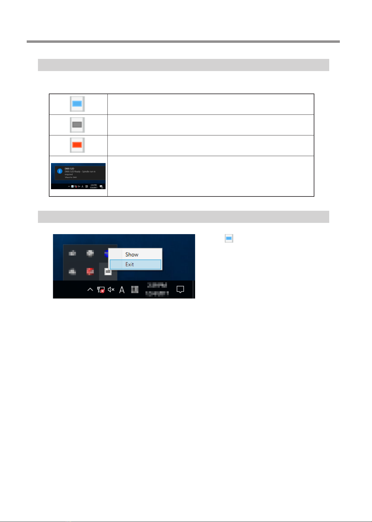
6Chapter 1 Operation Screen
VPanel Display in the Task Tray
When the VPanel icon is displayed in the task tray, the status of a connected milling machine is always monitored.The display of the
VPanel icon changes depending on the status of the milling machine. The meanings of the displays are shown below.
Indicates that at least one of the connected milling machines is on (is online).
Indicates that all the connected milling machines are o.
Indicates that an error has occurred on at least one of the connected milling machines.
If you hover the mouse pointer over this icon, you can check which machine has the error.
Messages are displayed automatically if an error occurs, during cutting, and in similar
situations. Even after the message disappears, if you hover the mouse pointer over this
icon, the status of each connected machine (such as Ready, Milling, Finished, Completed, or
Oine) will be displayed.
Messages prompting you to perform maintenance (such as "Spindle run-in required") will also
be displayed. In these situations, perform the maintenance work indicated by the message.
Exiting VPanel
Right-click in the task tray and click [Exit].
7
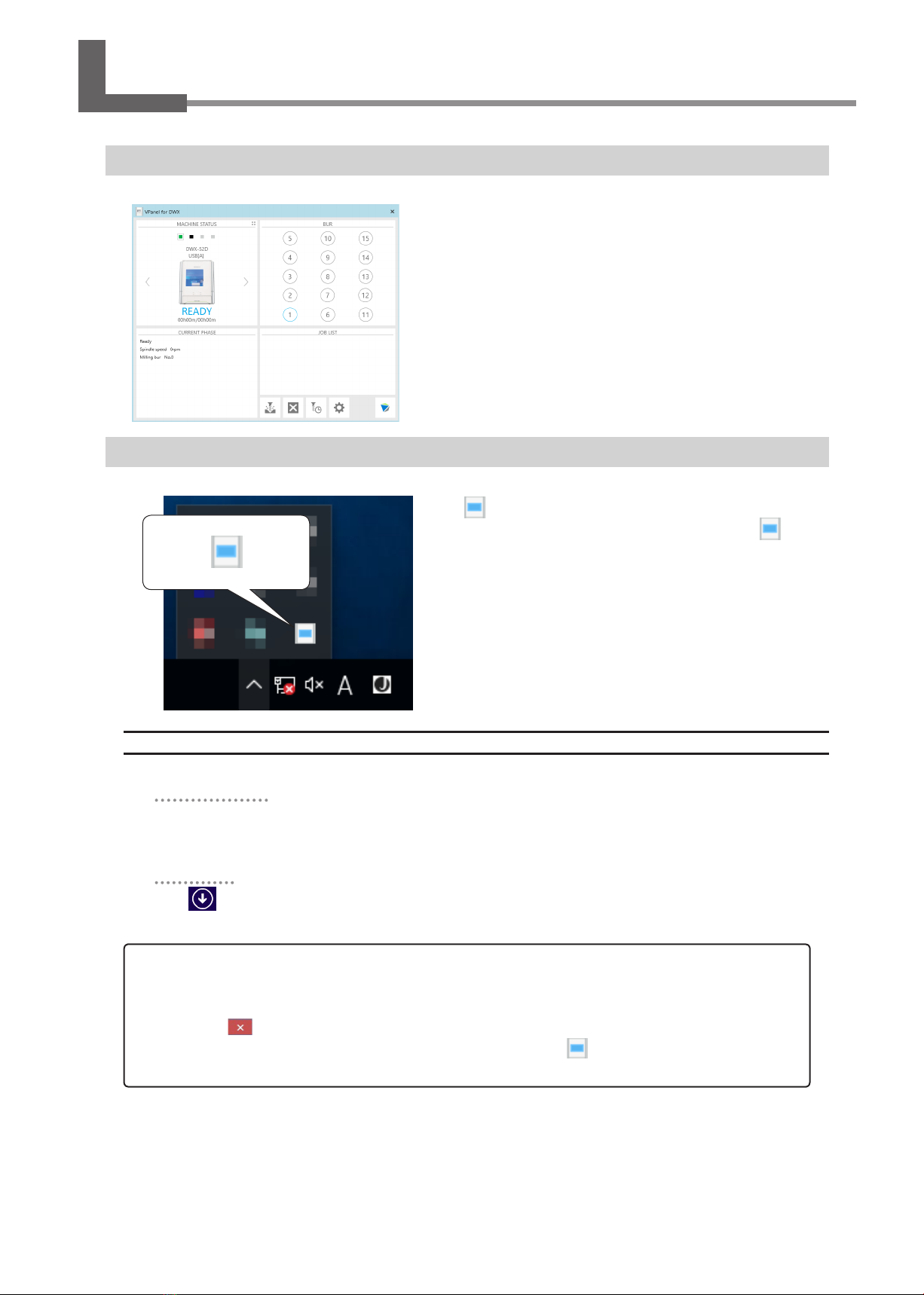
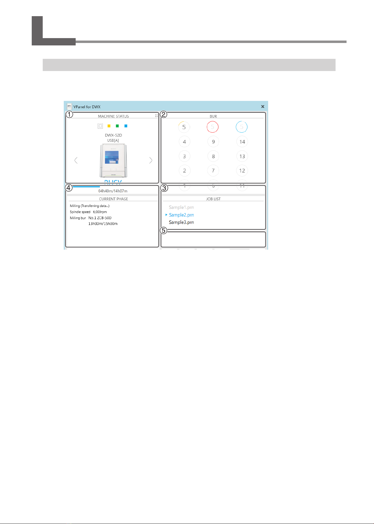
Chapter 1 Operation Screen
VPanel Window and Functions
Top Window
The top window displays the statuses of connected milling machines and an output list of milling data.When more than one machine
is connected, the machine displayed in the MACHINE STATUS window is the target of the operations.

VPanel Window and Functions
8Chapter 1 Operation Screen
No. Display Explanation
MACHINE
STATUS
The connected machines are displayed with square icons (). (In the above
gure, four machines are connected.) Click a icon to display the machine's
ID and name below the icon. The IDs of machines whose power is turned o
are shown with [-]. When you have connected multiple machines, you can
switch to a dierent machine to operate by clicking its icon. If you click the
icon of a connected milling machine, the status light of the milling machine
will ash.
(READY) Milling data can be received.
(BUSY) Operation is in progress.
(ERROR) An error has occurred.
(PAUSE) Operation is paused.
(COVER) The front cover is open.
(FINISH) Milling is complete.
(OFFLINE) No milling machines are connected.
(OFFLINE) The power of the milling machine is o.
When you have connected multiple machines, you can switch to a dierent
machine to operate by clicking its icon.
Displays the machine's operation status. A progress bar, the elapsed milling
time, and the estimated milling time are all displayed.
Estimated milling time
Elapsed milling time
Click this to display the operating status of all the connected machines in a
list. You can also select the machine to operate by clicking it in the displayed
list. To return to the previous display, click .
VPanel Window and Functions
9
Chapter 1 Operation Screen
No. Display Explanation
BUR
Displays the status of the function (Intelligent Tool Control) for automatically
switching the current milling bur with the set milling bur. Also, hover the
mouse pointer over the displayed number to display the name, work time, and
replacement time of the milling bur. The tool's remaining service life is indicated
by the length of the arc that surrounds the number. When the tool approaches
the end of its service life, the arc color changes to yellow. When the service life is
exceeded, the arc color changes to red.
Example
Usage: less than 75%
(green graph)
Example
Usage: 75% or more
(yellow graph)
Example
Usage: 100% or more
(red graph)
It is almost time to
replace the milling bur.
It is past time to replace
the milling bur.
"Milling bur management" dialog box
"P. 17 "Intelligent Tool Control (ITC) Function Settings"
"P. 45 "Milling Bur Replacement Time"
JOB LIST
Displays the data being milled, the milling data in standby, and the milling progress.
CURRENT
PHASE
Displays the operation status, spindle rotating speed, milling time, etc.
Displays the status of the connected machine.
Displays the spindle rotating speed of the connected machine.
Displays the name and work situation of the milling bur currently in use.
For example, "13h00m/15h00m" indicates that "13h00m" is the work
time and "15h00m" is the replacement time of the tool.
Outputs the milling data.
"P. 40 "STEP 6: Outputting Milling Data and Starting Milling"
Cancels output of milling data and other functions.
Allows for registration and selection of milling burs.
"P. 15 ""Milling bur management" Dialog Box"
Display the settings window.
"P. 10 ""Settings" Tab"
"P. 11 ""Maintenance" Tab"
"P. 12 ""Mail" Tab"
"P. 13 ""VPanel" Tab"
Click this to access the DGSHAPE Corporation website.

VPanel Window and Functions
10 Chapter 1 Operation Screen
"Settings" Tab
On this tab, you can congure settings related to the machine IDs and NC codes. When more than one machine is connected, the
machine selected in the top window becomes the target for the setting.
Display Explanation
NC code with
decimal point
Select how to interpret numbers in NC codes.
With "Conventional," the unit is interpreted as millimeter (or inch) when there is a decimal point, and as
1/1000 millimeter (or 1/10000 inch) when there is no decimal point.
With "Calculator," the unit is always interpreted as millimeter (or inch) regardless of whether there is a
decimal point. Select the scope of the application when selecting "Calculator." Select an appropriate
setting according to your CAM or NC code.
Initial setting: Conventional
Machine ID
When multiple machines are connected to one computer, it's necessary to set IDs for the machines.
Select the machine to use in the VPanel top window.
Initial setting: A
""Setup Guide" ("Connecting Multiple Units")
Important
To change an ID, be sure to follow the procedure explained in the "Setup Guide."
Version
VPanel: VPanel version
Firmware: Connected machine's rmware version
When more than one machine is connected, information for the machine selected in the top window is
displayed.
Override
You can adjust the milling speed and the spindle speed. This is useful when you want to change settings
such as the milling speed on the y while monitoring the milling status. Overrides are specied in
percentages.
For example, if the milling data command sent from the computer is 10,000 rpm, setting the override to
150% will cause the rotation speed to be 15,000 rpm.
Milling speed
Allows adjustment of the milling bur movement speed when milling the workpiece. The speed specied
by the command in the milling data is taken to be 100%. Inputting a large value will result in faster
speeds. Inputting a small value will result in slower speeds.
Spindle speed
You can adjust the spindle speed during milling. The number of rotations specied by the command in
the milling data is taken to be 100%. Inputting a large value will result in increased rotations. Inputting a
small value will result in decreased rotations.
The override will return to 100% when the milling machine is turned OFF.
In the top window, the spindle speed is shown as the speed specied by the milling data command
and not the speed after the override.
Setting an override does not let you perform operations beyond the machine's maximum or
minimum speeds (rotation speeds).
Point
Select the "Disable automatic blowing when milling is nished" check box to stop the automatic blowing function*.
*: This is a function that automatically blows air on the workpiece when milling is nished in order to blow o the milling
waste.
VPanel Window and Functions
11
Chapter 1 Operation Screen
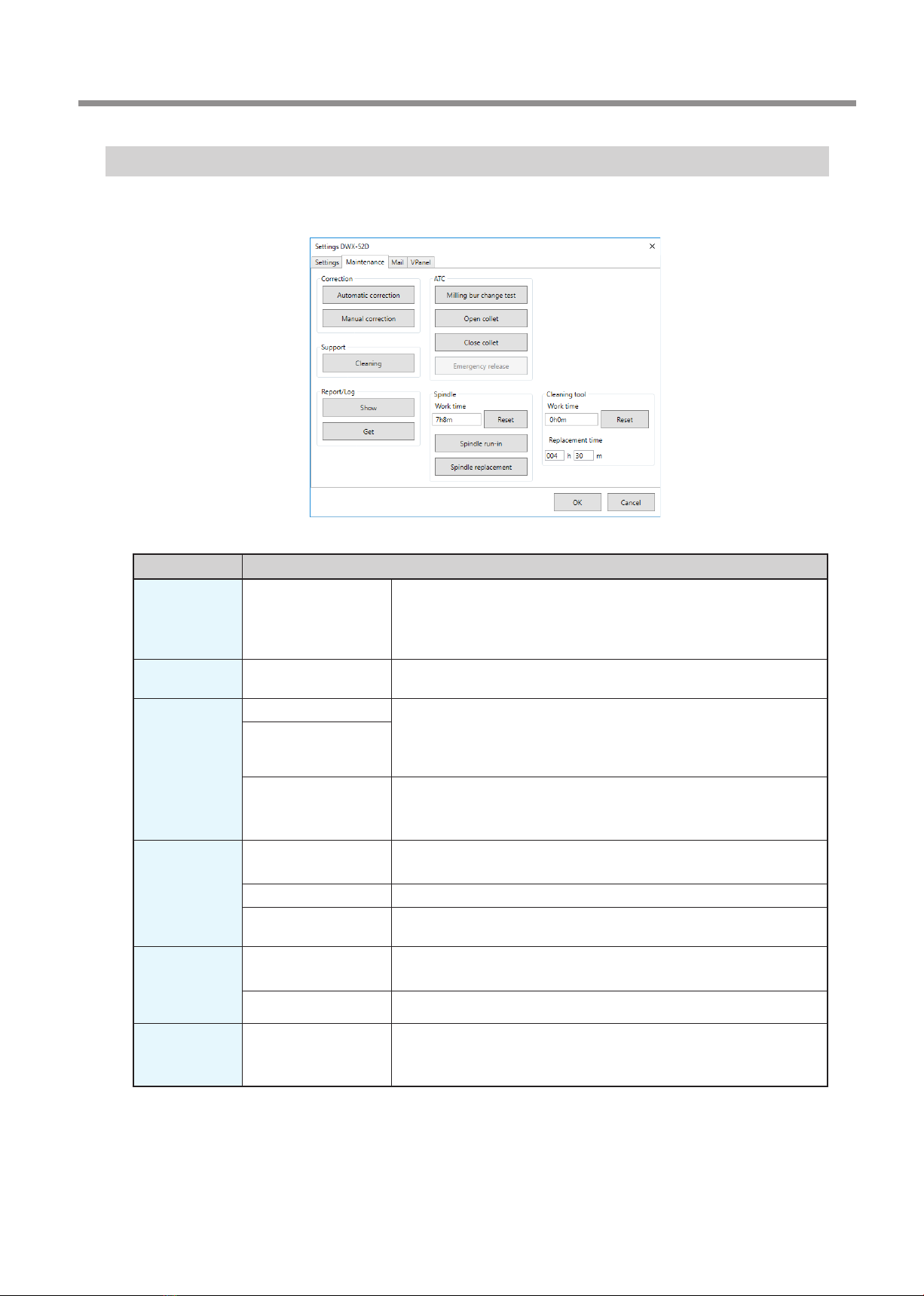
"Maintenance" Tab
On this tab, you can perform operations related to maintenance, including automatic correction of the milling machine and system
reporting.When more than one machine is connected, the machine selected in the top window becomes the target for the operations.
Display Explanation
Correction Automatic correction/
Manual correction
Correct the ATC magazine position or the rotary axis position. Normally
use [Automatic correction].
"P. 53 "Correcting the Milling Machine"
"P. 14 ""Manual correction" Dialog Box"
Support Cleaning Click this button to open the "Cleaning" dialog box.
"P. 18 ""Cleaning" Dialog Box"
ATC Milling bur change test Perform tests, maintenance, and other tasks related to operation with
the ATC magazine.
"P. 50 "Periodic Maintenance"
"P. 49 "Care and Storage of Detection Pin and Automatic Correction Jig"
Open collet/Close collet
Emergency release This button is enabled when the power is turned on while the front cover
is open. Use this function if the initial operations cannot be performed
because, for example, the milling bur is caught on the workpiece.
Spindle Reset "Work time" displays the work time of the spindle.
After replacing the spindle unit, click [Reset] to reset the value to 0.
Spindle run-in
"P. 52 "Spindle Run-in (Warm-up)"
Spindle replacement Click this button to open the "Spindle replacement" dialog box.
"P. 51 "Replacing Consumable Parts"
Report Display Display the rmware version, the total operating hours, and the error
dialog box.
Get Obtain a le in which the information of the various logs is collected.
Cleaning tool Reset "Work time" displays the work time of the cleaning tool. After replacing
the cleaning tool, click "Reset" to reset the value to 0. You can use
"Replacement time" to set the replacement time of the cleaning tool.

VPanel Window and Functions
12 Chapter 1 Operation Screen
"Mail" Tab
Settings on this tab can be congured so that a notication email is sent when milling nishes, when an error occurs, or when
maintenance is complete. When more than one machine is connected, all of the machines become the targets for the settings.
Select the "Use mail notication" check box to enter each item.
Display Explanation
Receiver address
Enter the receiver's email address. You can enter multiple addresses by separating them with commas.
Sender address Enter the sender's email address. Enter the email address being used on the computer on
which VPanel is installed.
Server host name Enter the name of the outgoing mail server (SMTP server name) for the email address entered
for the sender’s address.
Server port number Enter the port number of the outgoing mail server for the email address entered for the
sender’s address.
Use SSL connection
Select this check box to use a security-protected connection (SSL). Select or clear this check
box according to the settings of the outgoing mail server for the email address entered for the
sender’s address.
Use SMTP
authentication
User name / Password
Select this check box to perform authentication before sending emails. Input the user name
and password for authentication. Select or clear this check box according to the settings of the
outgoing mail server for the email address entered for the sender’s address.
Send test
Click [Send test] to send a test email. If the following email is received at the address specied
with "Receiver address," the conguration of the settings is complete.
Subject: <Machine name> Body: Test
If the sending of the email fails, the message "The email could not be sent." will be displayed.
Check the content in the input elds again.
Notication timing Notication emails will be sent for the items whose check boxes are selected.
Important
* It may be impossible to send emails because of the settings of software such as security software. If emails cannot be sent, check
the settings of the security software being used as anti-virus software or for a similar purpose.
* For detailed information about the email settings, consult your network administrator.
* VPanel does not support SMTP over SSL (SMTPs).

VPanel Window and Functions
13
Chapter 1 Operation Screen
"VPanel" Tab
On this tab, you can set the automatic starting of VPanel and the layout of the top window.When more than one machine is connected,
the machine selected in the top window becomes the target for the setting.
Display Explanation
Layout
Select the layout of the top window.
The selected layout is displayed in the top window.
Initial setting: "Standard"
Standard DWX-52DC compatible
Click "Reset" to return to the "Standard" layout. The screen is displayed in the top window.
Connected machine
selection
Click "Select" to display the screen for selecting the machine to operate.
The machines that can be operated and that are registered on the computer are displayed
in the upper row. The machine that is the target for operation from VPanel is displayed in the
lower row.
Drag the images of the machines in the lower row to the left and right to change the display
order of the machines in the top window.
Run VPanel at PC
start‑up
When this check box is selected, VPanel will start automatically when Windows starts, and the
VPanel icon will be displayed in the task tray.
Initial setting: Selected

VPanel Window and Functions
14 Chapter 1 Operation Screen
"Manual correction" Dialog Box
In this dialog box, you can perform manual correction of the milling machine. Perform correction to precisely adjust the accuracy.
When more than one machine is connected, the machine selected in the top window becomes the target for correction.
* Perform automatic correction before performing this correction.
Display Explanation
Distance
Correct moving distances in the X, Y, and Z directions. Set the correction value while considering
the initial moving distance as 100.000%.
Initial setting: 100.000%
A axis back side
Correct the angle when the A axis is rotated 180 degrees. Set the correction value while
considering the initial setting as 0.00 degrees.
Initial setting: 0.00 degrees
Origin point
Correct the origins of the X, Y, and Z axes. Set the correction value while considering the initial
setting as 0.00 mm.
Initial setting: 0.00 mm
Clear these values when
executing the automatic
correction
Select this check box to reset the values for "Distance," "Origin point," and "A axis back side"
when performing automatic correction.
Initial setting: Selected
VPanel Window and Functions
15
Chapter 1 Operation Screen
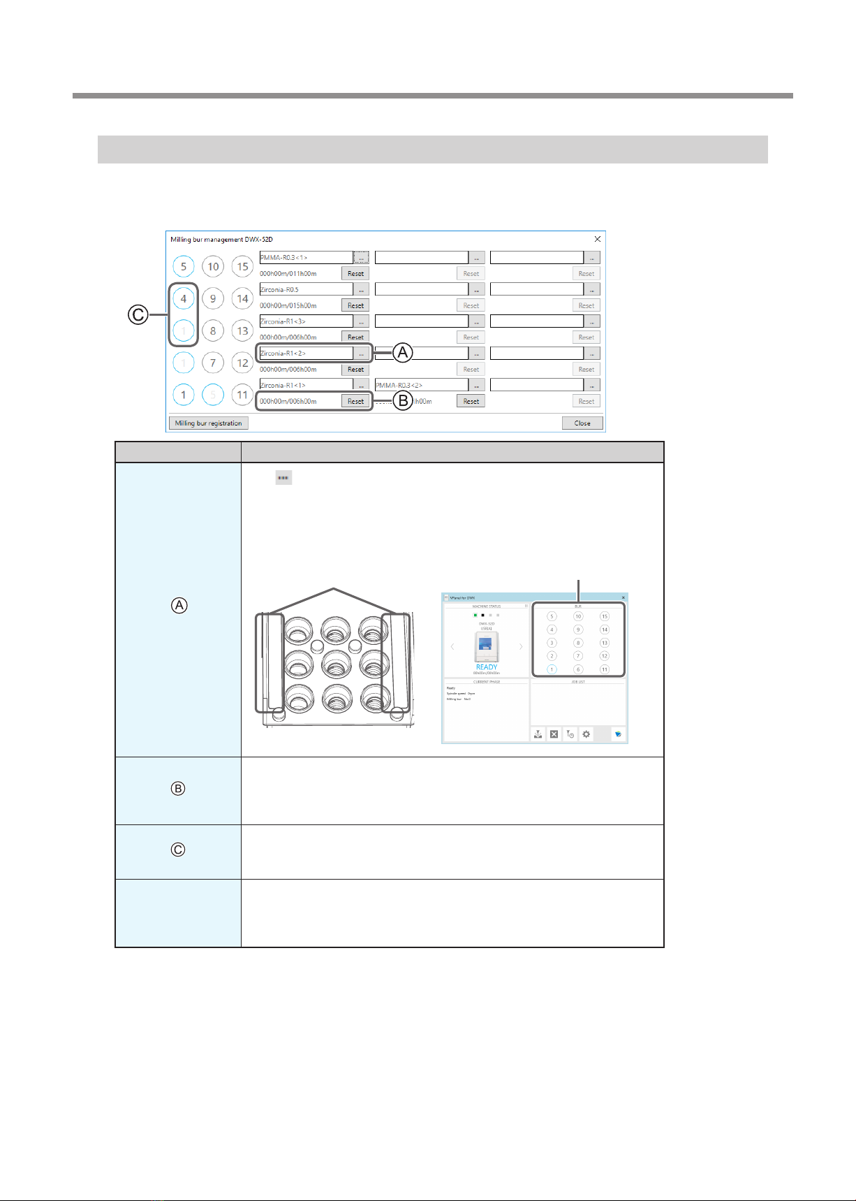
"Milling bur management" Dialog Box
By selecting a milling bur to be used, the work time of the selected milling bur will be recorded automatically. In addition, when
the bur reaches the preset replacement time, a warning message will be displayed. When more than one machine is connected, the
machine selected in the top window is managed.
Symbol or display Explanation
Click to display the milling burs for which "Milling bur registration" was
performed. Numbers 1 through 15 match the milling bur stocker numbers on the
machine's ATC magazine. The name and work situation of the milling bur currently
in use will be displayed on the top window.
"P. 16 ""Milling bur registration" Dialog Box"
Displays the work time and replacement time of the selected milling bur. When
the bur reaches the preset replacement time, a warning message will be displayed.
The replacement time can be changed from "Milling bur registration." After
replacing the milling bur with a new one, click "Reset" to set the work time to 0.
You can automatically replace milling burs that have reached their replacement
time during milling by setting multiple milling bur stockers as a single unit.
"P. 17 "Intelligent Tool Control (ITC) Function Settings"
Milling bur
registration
Here you can register milling burs whose work time you want to manage or
remove burs you no longer want to manage. Click this button to display the
"Milling bur registration" dialog box.
"P. 16 ""Milling bur registration" Dialog Box"
1 11
12
13
2
3
Milling bur stocker number Milling bur info
VPanel Window and Functions
16 Chapter 1 Operation Screen
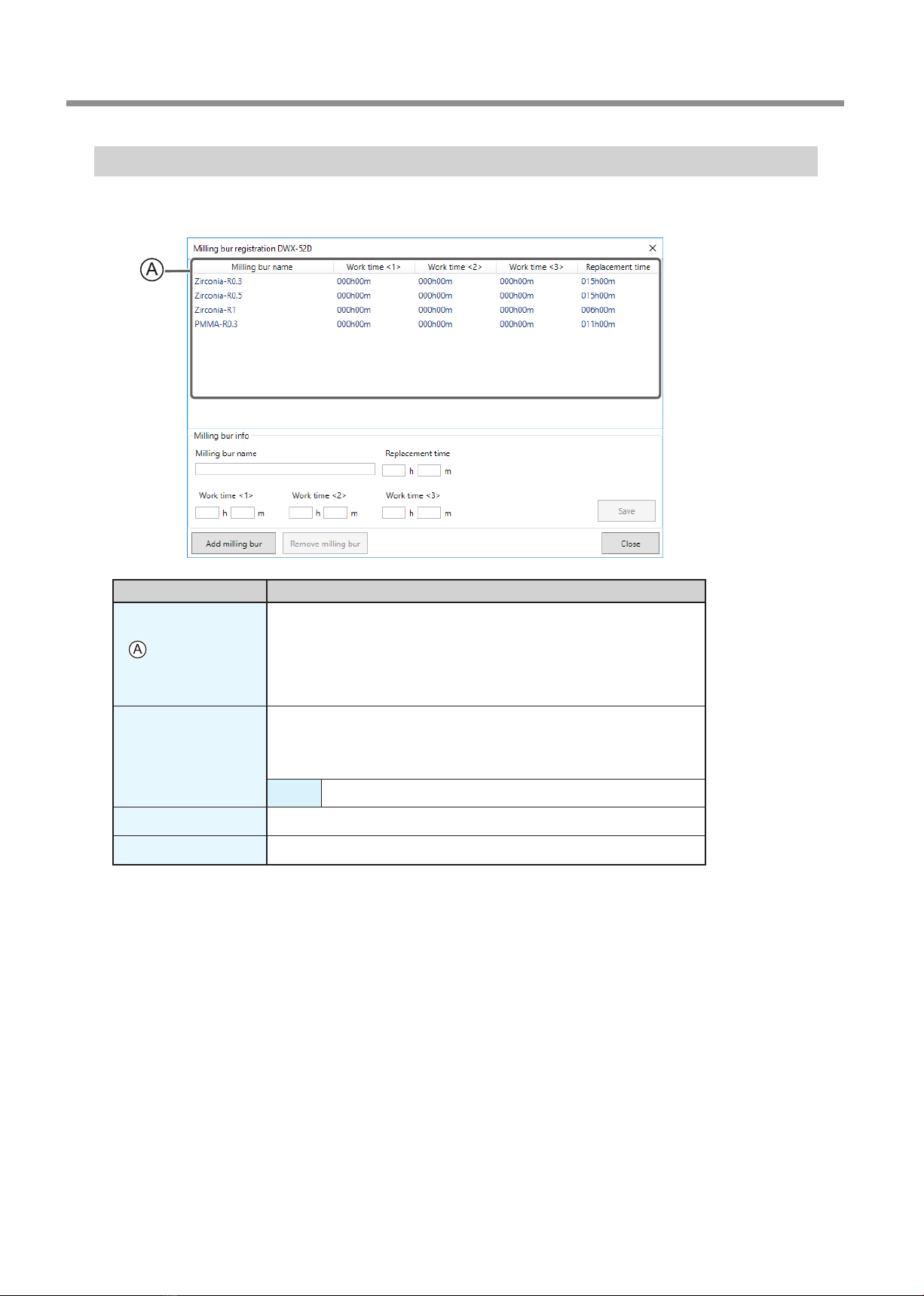
"Milling bur registration" Dialog Box
A milling bur's registration information can be changed in order to change the work time or the replacement time. When more than
one machine is connected, the milling bur for the machine selected in the top window will be the target.
Display Explanation
Displays the names, work times, and replacement times of the registered
milling burs. If you are using the Intelligent Tool Control function, the work
time for the milling bur set as the second milling bur is displayed under Work
time <2> and the work time for the milling bur set as the third milling bur is
displayed under Work time <3>.
"P. 17 "Intelligent Tool Control (ITC) Function Settings"
Milling bur info
Allows the milling bur name, work time, and replacement time of the milling
bur selected in the list to be edited. Because replacement times depend on the
type of milling bur or workpiece as well as the milling conditions, adjust the
replacement time value as necessary.
Save Saves the edited content (the existing content is overwritten).
Add milling bur Registers additional milling burs. You can register up to 20 milling burs.
Remove milling bur Removes the milling bur selected in the list.
VPanel Window and Functions
17
Chapter 1 Operation Screen
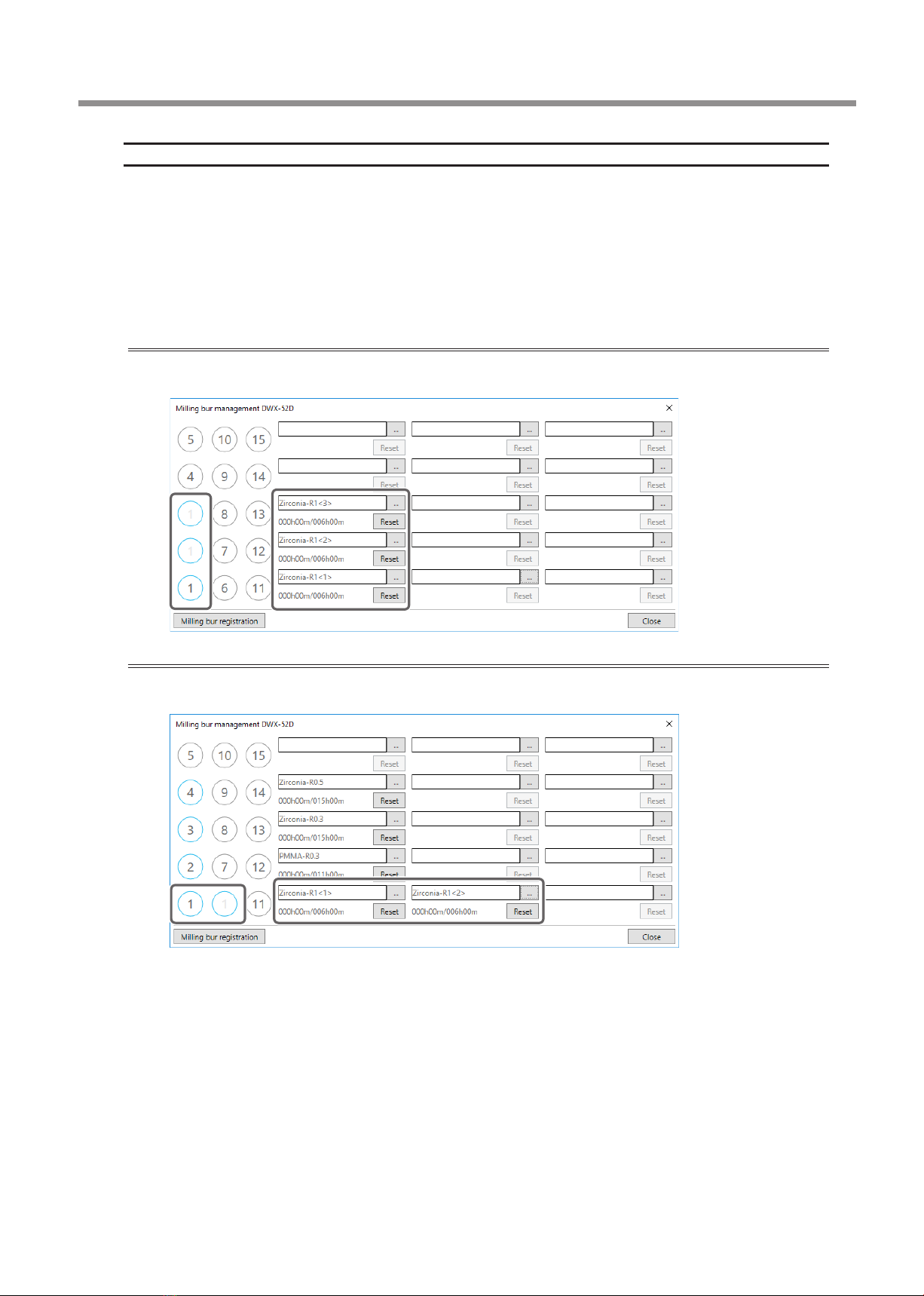
Intelligent Tool Control (ITC) Function Settings
This machine is equipped with an Intelligent Tool Control (ITC) function. If you set the ITC function, when the milling bur being used
approaches its replacement time, it is automatically switched with the next milling bur. This makes it possible to continue milling for a
long time without any loss in milling quality. Use this dialog box to group together the milling burs that will be switched automatically.
Register milling burs with the same name to set them as a single unit. For milling burs that are the same type, you can set a maximum
of three milling burs and a minimum of two milling burs.
When setting three milling burs as a single unit
Set three milling burs with the same name in the milling bur stocker.
(In the example in the following gure, (1) to (3) are set to the same name.)
When setting two milling burs as a single unit
Set milling burs with the same name in the milling bur stocker.
(In the example in the following gure, (1) and (6) are set to the same name.)
VPanel Window and Functions
18 Chapter 1 Operation Screen
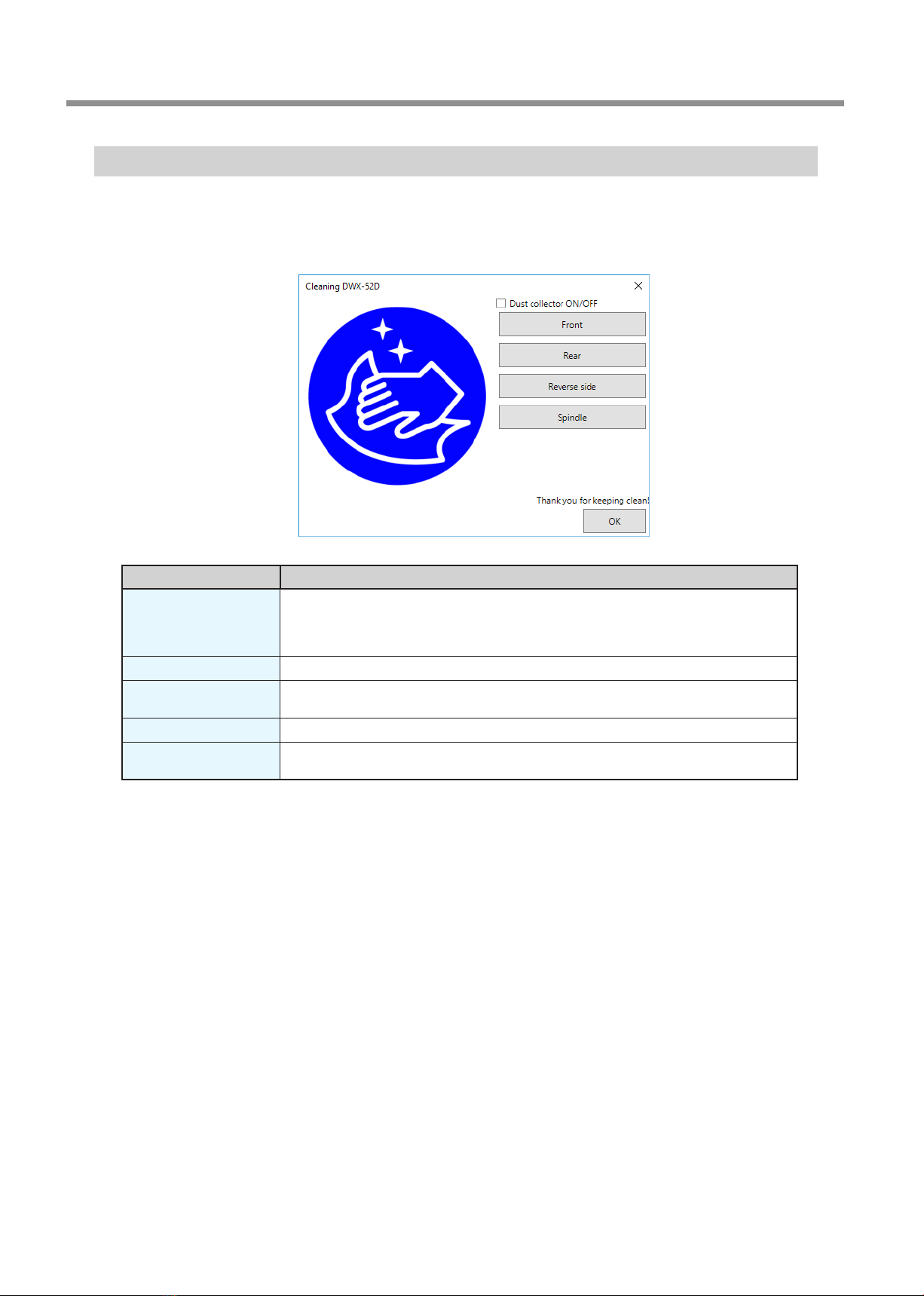
"Cleaning" Dialog Box
Use this dialog box when you clean the machine. You can use it to perform operations such as moving the rotary axis unit and the
spindle. To verify the operation, place the mouse pointer over the button to switch the VPanel illustration.
" P. 48 "Cleaning after Milling Finishes"
Display Explanation
Dust collector ON/OFF
Turns the dust collector ON/OFF.
(For dust collectors with a linking function and connected to the expansion port with a linking
cable.)
For details on the dust collector, see the DWX-52D "Setup Guide."
Front Moves the rotary axis unit to the front. Use this function when cleaning the rotary axis unit.
Rear Moves the rotary axis unit to the back. Use this function when cleaning the back of the milling
area.
Reverse side Turns the clamp over. Use this function when cleaning the back side of the clamp.
Spindle Moves the spindle unit to a location where it is visible. Use this function when cleaning around
the spindle unit.

19
Chapter 2 Milling
Using/Reading the Built-In Panel....................................................................................20
Using/Reading the Built-In Panel........................................................................................................... 20
Statuses Indicated by Status Light Color ............................................................................................ 20
Switching the Power On or Off .......................................................................................21
Switching the Power On ........................................................................................................................... 21
Switching the Power O........................................................................................................................... 21
Preparing for Milling........................................................................................................22
CAM Settings Necessary for Milling...................................................................................................... 22
Preparing a Workpiece (Usable Workpieces)..................................................................................... 22
Preparing a Milling Bur (Usable Milling Burs).................................................................................... 22
Cleaning Tool ................................................................................................................................................ 23
Compressed Air (Setting the Regulator)............................................................................................. 23
Starting Milling ................................................................................................................24
STEP 1: Attaching a Workpiece to the Adapter................................................................................. 24
STEP 2: Attaching the Adapter to the Machine ................................................................................ 33
STEP 3: Loading the Milling Bur ............................................................................................................. 36
STEP 4: Loading the Cleaning Tool........................................................................................................ 38
STEP 5: Checking the Regulator Settings............................................................................................ 40
STEP 6: Outputting Milling Data and Starting Milling ................................................................... 40
STEP 7: Removing the Adapter from the Machine.......................................................................... 43
Aborting Output.......................................................................................................................................... 44
Removing Milling Data in Standby from the Output List ............................................................. 44
Automatically Switching Out the Worn Milling Bur (Intelligent Tool Control) ...................... 45
20 Chapter 2 Milling
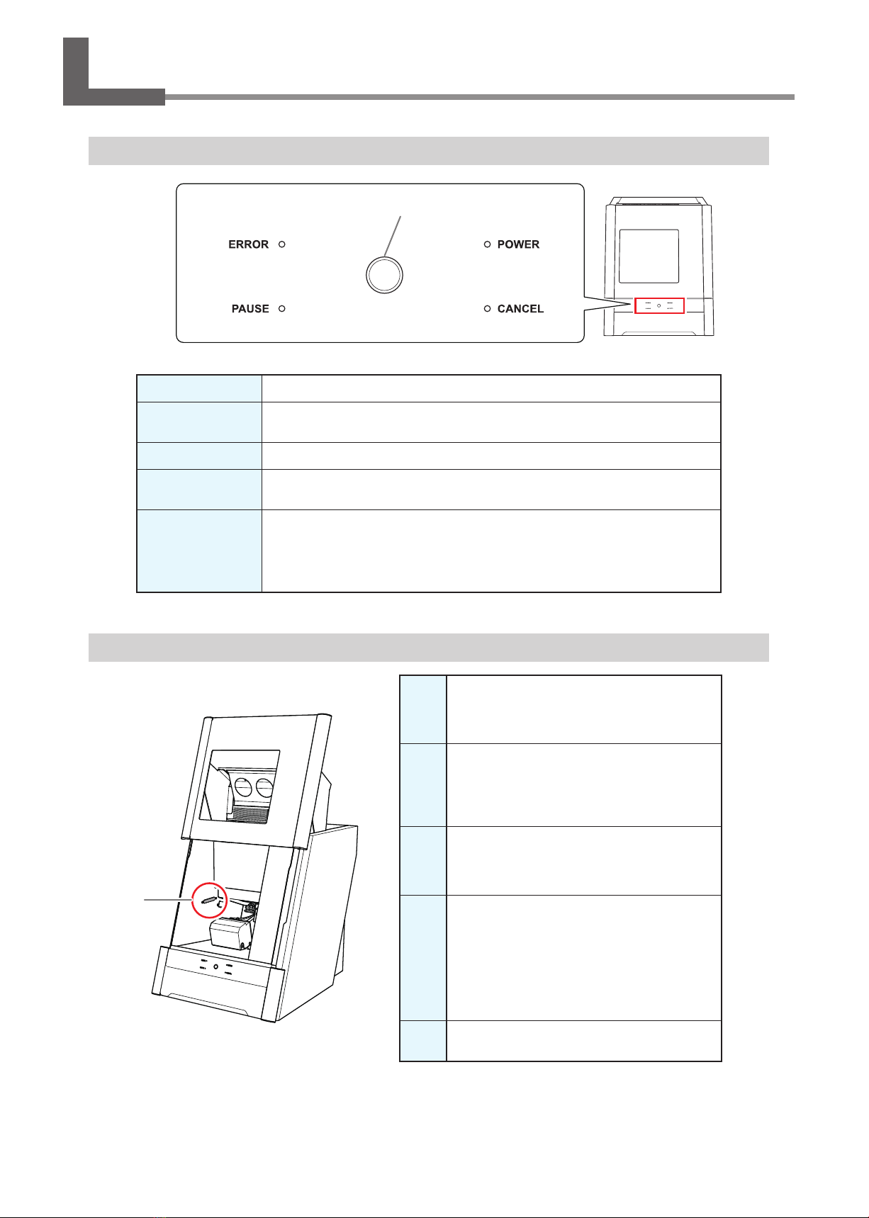
Using/Reading the Built‑In Panel
Using/Reading the Built‑In Panel
ERROR Flashes when an error has occurred.
PAUSE Lights when operation is paused.
POWER Lights when the power is turned on.
CANCEL Flashes when data is being cancelled and during the initial operations.
Milling data received while this light is ashing will be cancelled.
Operation button
Pressing this button during milling will pause or restart the machine.
Pressing and holding this button during milling will abort milling or clear some errors.
Pressing this button in standby will rotate the rotary axis position 180 degrees.
Flashes during the initial operations, during spindle rotation, and during similar
operations. The button will light when the machine is on and in any other status.
Statuses Indicated by Status Light Color
Blue
The machine is in standby or is performing the initial
operations. The light will turn o if no operation is
performed for 30 seconds when in standby, causing the
machine to sleep.
White
When lit white, milling is being performed or
has been paused, or the front cover is open. Also
ashes in white when the dust collector is in
standby.
Yellow
When lit in yellow, an error has occurred and the
machine has been paused. Check the error details
shown on VPanel. Press the operation button on
the built-in panel to resume milling.
Red
When lit or ashing in red, an error has occurred
and milling has been stopped. Milling cannot be
resumed.
Check the error details shown on VPanel. When lit
in red, holding down the operation button on the
built-in panel will cancel milling and return the
machine to the ready status. When ashing in red,
turn o the power and start the machine again.
Off The light turns o when the machine is in the sleep
state or the power is turned o.
Status light
Operation button
Table of contents
Other DGSHAPE Dental Equipment manuals


