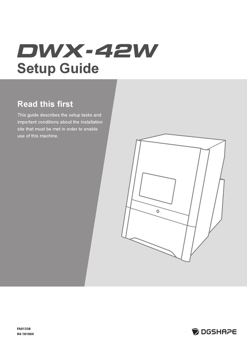
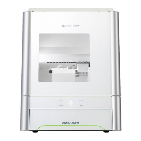
DGSHAPE DWX-53DC Assembly instructions

Congratulations on your purchase of this product this time.
•
To ensure safe and correct use of this product and to gain a thorough understanding of its performance, please read this manual
carefully and retain it for future reference.
•
Unauthorized copying or copying of all or part of the contents of this manual is prohibited.
•
The specifications of this product and the contents of this manual are subject to change without notice.
•
Contact us if you notice any questions, mistakes, or omissions in this product or the contents of this manual.
•
We assume no responsibility for any direct or indirect damage caused by the use of this product, whether or not it is faulty.
•
We shall not be liable for any direct or indirect damages caused to the product manufactured by this product.
FA02363 Copyright © 2022 DGSHAPE Corporation
R1-220907
https://www.dgshape.com/
Installer Guide

Introduction ............................................................................................................................................................... 2
ABOUT THE MACHINE..................................................................................................................................................
3
Unique features ........................................................................................................................................................3
Pre-installation check.........................................................................................................................................................
4
Installation and Installation .......................................................................................................................4
Installation location...................................................................................................................................................
5
Temperature and humidity ........................................................................................................................6
Installation space.......................................................................................................................................7
What's in the Box ...............................................................................................................................................................
9
Installation........................................................................................................................................................11
PREPARATION TO USE THE MACHINE ................................................................................................................
12
Check before operation ...........................................................................................................................12
Install the aircraft............................................................................................................................................................
15
Remove the fasteners ..............................................................................................................................15
Connect the power cord........................................................................................................................ 19
Turn on the power................................................................................................................................. 21
Retighten the screws of the air nozzle. ......................................................................................22
Attach the dust collector..........................................................................................................................24
Install the regulator...................................................................................................................25
Connect to a computer......................................................................................................................................................
29
System requirements ...............................................................................................................................29
Software to be installed ...........................................................................................................30
Install software.................................................................................................................. 31
Connect to a computer.............................................................................................................32
Show VPanel......................................................................................................................................... 39
Exiting VPanel...................................................................................................................................... 40
Connect multiple units....................................................................................................................................................
41
Registering another aircraft .....................................................................................................................41
Switching the Aircraft Operated by VPanel......................................................................................... 44
Changing the Name and Images of the Aircraft Displayed on VPanel.....................................................45
Before starting work .......................................................................................................................................................
47
Selecting the Aircraft to Use with VPanel for DWX ...............................................................................47
Running in the disc changer ....................................................................................................48
Perform spindle habituation operations .....................................................................................50
Correcting the cutting position automatically ..........................................................................................52
Turn off ....................................................................................................................................58
Appendix...........................................................................................................................................................59
Specifications.................................................................................................................................................
60
Expansion terminal..................................................................................................................................60
Coordinate...............................................................................................................................................61
Dimensions .............................................................................................................................................62
List of specifications ...............................................................................................................................66
System-Requirements for USB Connectivity...........................................................................................67
1
Tabl
e of
Con
tent
s


2
Introducti
on
Introduction
ABOUT THE MACHINE ............................................................................................................
3
Unique features...................................................................................................................3
Pre-installation check....................................................................................................................
4
Installation and Installation......................................................................................4
Installation location..............................................................................................................
5
Temperature and humidity.......................................................................................6
Installation space.....................................................................................................7
What's in the Box..........................................................................................................................
9

3
Introducti
on
Relevant
informatio
n
Unique features
This machine is a dental cutting machine that uses dental cutting ceramics, resin materials for dental cutting, dental casting
wax, or dental non-cast cobalt-chromium alloy to make prostheses such as crowns, copings, and bridges.
You can create high-quality prostheses by installing special software on your computer and connecting the instrument.
The machine's disc changer automatically manages and switches up to six cutting materials. Continuous machining is
possible while using materials in use without waste.
Please refer to our site for the latest information on this machine.
•
https://www.dgshape.com/
ABOUT THE MACHINE

4
Introducti
on
Note
Loading/unloading and installation shall be carried out by at least four persons.
Forcible work with a small number of persons may injure your body. If it falls, it may cause injury.
Note
Hold the projector by the parts shown in the illustration when lifting it.
x4
Important
Do not have milling area covers, adaptor area covers, tool area covers and dust harvesting hose
attachments.
Installation and Installation
The weight of the main unit alone is 120 kg . Take care when loading/unloading and installing.
Pre-installation check

Pre-
installation
check
5
Introducti
on
Warning
Install the unit in a place that is level, stable, and capable of withstanding the weight of the unit.
The total weight of the instrument is more than 120 kg . Failure to do so may result in a serious accident such as a fall,
fall or collapse.
Warning
Do not install the product in a place exposed to fire.
Otherwise, it may ignite the machining scrap. Powdery things are very combustible and can burn even if they are
metal.
Warning
Do not install the product near flammable materials or in a place filled with gas.
Failure to do so may result in a fire or explosion.
Warning
Do not install the product outdoors, in a place exposed to water, or in a place with high humidity.
Electric leakage may cause electric shock or fire.
Warning
Keep the power plug easily accessible at all times.
This is for quick disconnection of the power plug in case of emergency. Install the equipment near the power
outlet. Also, leave enough space for the power cord to be brought into close proximity to the outlet.
Installation location
•
Do not install the product in a location subject to large changes in temperature and humidity.
•
Do not install the product in a place subject to shaking or vibration.
•
Do not install the product in a dusty location.
•
Do not install the product in direct sunlight or near heating and cooling equipment.
•
Do not install the product in a location where there is a lot of electrical or magnetic noise, such as electromagnetic
waves.
•
Do not install the product in an atmosphere containing silicone-based substances (oil, grease, spray, etc.).
Failure to do so may cause contact failure of the switch or malfunction of the ionizer.

Pre-
installation
check
6
Introducti
on
Important
Use the machine in an environment where the temperature is kept as constant as possible. Large changes in the
temperature of the installation environment may affect the machining quality.
Temperature and humidity
Install the product in a place with specified conditions (temperature, humidity, etc.). Failure to observe this precaution
may result in damage to the unit.
•
Temperature : 5
~
40 ℃
•
Humidity: 35 to 80% RH (no condensation)

Pre-
installation
check
7
Introducti
on
Relevant
informatio
n
Installation space
Allow at least the following space for installation.
Installation space
Working space
A
800 mm
B
900 mm
C
1,800 mm
D
1,900 mm
Secure sufficient space for the adapter area cover or tool area cover to be opened.
H
912 mm
•
P. 62 "External Dimensions"

Pre-
installation
check
8
Introducti
on
Height to be installed
Install the product at least 0.6 m from the work floor.
This unit is a tabletop-mounted device. Install the product so that it is easily accessible to the power switch and other operating
parts during operation.

9
Introducti
on
Your digital piano comes with all the items shown below. Check that all parts are included.
Power cord/power plug
adapter (1 each)
USB cable (1)
Regulator (1)
Drain hose (1)
Air hose (1)
Adapters (6)
Automatic correction jig (1)
Adapter for pin material (1)
Open Edge Adapter (1)
*1
Milling bar positioning jig
(1)
Milling bar holder (15)
Detection pin (1)
Tool storage area (1)
Collet mounting/dismounting
jig (1)
T Six Sumi screwdriver (1)
L Six Sumi wrench (1)
(1)
Set Screw (25)
Screw (spare
for adapter) (8)
Screw (spare for adapter for
pin material) (2)
Black screw
(for regulator) (4)
What's in the Box

Pre-
installation
check
10
Introducti
on
Important
When using a torque screwdriver with a sleeve attached, do not loosen screws or screws that are tightened to a
torque higher than the value printed on the sleeve. The sleeve may be damaged.
What's in the Box
Cleaning fabric (1)
Milling bar (4)*2
Torque driver*3
Tablet Holder Right (1)
Screw (1)
Tablet Holder Left (1)
Screw (1)
Adapter rack (1)
Cushion
(for tablet) (4)
Adapter ID label
(for option) (1)*4
Quick Access Guide (1)
Safety Instructions (1)
*1 Attach the adapter ID label (for option) to the adapter base. The adapter ID label can be used with any number.
*2 ZRB-200D, ZPB-100D, ZPB-50D and ZPB-30D (1 per)
*3 Handle (2) bit (1.5 mm, 2.5 mm, 3.0 mm) (1 each) Sleeve (0.3 N•m, 0.6 N•m) (1 each)
*4 Used when the optional adapter is purchased.

11
Insta
llatio
n
Installation
PREPARATION TO USE THE MACHINE ...........................................................................
12
Check before operation..........................................................................................12
Install the aircraft.......................................................................................................................
15
Remove the fasteners.............................................................................................15
Connect the power cord ...................................................................................... 19
Turn on the power............................................................................................... 21
Retighten the screws of the air nozzle.........................................................22
Attach the dust collector........................................................................................24
Install the regulator ....................................................................................25
Connect to a computer ................................................................................................................
29
System requirements .............................................................................................29
Software to be installed.............................................................................30
Install software.................................................................................... 31
Connect to a computer..............................................................................32
Show VPanel....................................................................................................... 39
Exiting VPanel .................................................................................................... 40
Connect multiple units ..............................................................................................................
41
Registering another aircraft ...................................................................................41
Switching the Aircraft Operated by VPanel....................................................... 44
Changing the Name and Images of the Aircraft Displayed on VPanel ...................45
Before starting work..................................................................................................................
47
Selecting the Aircraft to Use with VPanel for DWX..............................................47
Running in the disc changer......................................................................48
Perform spindle habituation operations ......................................................50
Correcting the cutting position automatically ........................................................52
Turn off......................................................................................................58

Pre-
installation
check
12
Insta
llatio
n
PREPARATION TO USE THE MACHINE
Important
The machine cannot be machined without a dust collector.
Warning
Be sure to operate the dust collector.
Machining scraps and workpieces may ignite/cause injury to personnel.
Warning
Do not use a vacuum cleaner to vacuum off any machining scraps.
Use of an ordinary vacuum cleaner to breathe fine particles may cause a fire or explosion.
Check before operation
Dust collector
Since this machine cuts materials, machining scraps are produced during machining. A separate dust
collector must be provided. Insert the dust collector hose into the dust collector pipe of the machine and
use it.
Prepare a dust collector that meets the following conditions.
•
Static pressure: 26 kPa or more
•
4
㎥
/min Above
•
Dust collecting hose [A] which fills the inner or
outer diameter of the dust collecting pipe
When a dust collecting hose () is put on the outside
of the dust collecting pipe (): Inner diameter of the
dust collecting hose: 50.8 mm
[B]
When inserting the dust collecting hose () inside
the dust collecting pipe (): Outer diameter of the
dust collecting hose: 45.6 mm

13
Insta
llatio
n
Warning
The pressure of compressed air shall be 1.0 MPa or less.
Exceeding this value may cause a serious accident such as an explosion.
Warning
The compressed air to be supplied shall be free from water, oil, chemicals, and foreign matter.
Parts may deteriorate and rupture, or contaminants may scatter and cause damage.
Warning
Do not supply compressed air until the air hose is securely connected.
Otherwise, an unexpected accident may occur.
PREPARATION TO USE THE MACHINE
Compressor (compressed air supply source)
This machine requires compressed air. A compressor must be prepared separately.
Prepare a compressor that meets the following conditions.
•
Control pressure: within 0.5 to 1.0 MPa
•
Air flow: 66 L/min or more (per unit)
•
Oil-free type (Dislike intrusion of foreign matter into compressed air.)
•
With dryer (Moist air may cause rust.)

Pre-
installation
check
14
Insta
llatio
n
Important
Be sure to use the supplied regulator to supply compressed air.
PREPARATION TO USE THE MACHINE
Air hose
Air hose connecting compressor and regulator (1)
Prepare an air hose that meets the following conditions.
•
Hose O.D. ():6 mm (polyurethane resin tube)
Water receiver
The water accumulated in the regulator bowl is discharged little by little, so prepare a water reservoir.

15
Insta
llatio
n
Important
Be sure to check that the power cord is not connected before removing the fixture.
Important
Be careful not to drop screws or fasteners into the aircraft. Doing so can damage the unit or cause it to malfunction.
Important
The torque screwdriver uses a handle and bit. Do not use sleeves.
Remove the fasteners
•
To protect the unit from transport vibrations, the unit is fitted with four fasteners. Once the aircraft is installed, remove all
fasteners. Turning on the power while the fixture is attached to the aircraft may cause malfunction or failure.
•
Fixtures are required for transport. Keep this manual in a safe place so as not to lose it.
Necessary items
Procedure
1.
Open the milling area cover.
2.
Remove the four screws with a torque screwdriver to remove fixture A.
Torque
screwdriver
(0.6 N
・
m)
Install the aircraft

16
Insta
llatio
n
Install the
aircraft
Important
0.6 Attach and tighten the N•m red sleeve to the torque screwdriver.
Important
The torque screwdriver uses a handle and bit. Do not use sleeves.
NOTE
Be sure to remove fixture B and screws. The removed fixture B and screws are required for transfer.
Keep the warranty in a safe place.
3.
Use a Torque Driver to tighten the four mounting screws of Fixture A.
4.
Open the adapter area cover.
5.
Remove the screws with a torque screwdriver and remove fixture B.

Install the
aircraft
17
Insta
llatio
n
B
NOTE
The screws need not be removed simply by loosening them to make the work more efficient and to prevent
the screws from being lost.
6.
Open the tool area cover.
7.
Remove the maintenance cover.
a.
Loosen the screws securing the maintenance cover by hand about two turns.
b.
Remove the maintenance cover.
Lift the maintenance cover upward and when the hole in the maintenance cover comes to the position
where it passes through the screw, pull the maintenance cover toward you to remove it.
8.
Remove the two screws with a torque screwdriver to remove fixture C.
9.
Remove the three screws with a torque screwdriver to remove fixture D.

Install the
aircraft
18
Insta
llatio
n
Important
The torque screwdriver uses a handle and bit. Do not use sleeves.
NOTE
To prevent screws from falling into the aircraft, gently press the fixture against the head of the screw with your
hand while evenly loosening the screws and remove them together with the fixture.
Be sure to remove fixtures C and D and screws. Removed fasteners C, D and screws are required for
transfer. Keep the warranty in a safe place.
Table of contents
Other DGSHAPE Dental Equipment manuals
Popular Dental Equipment manuals by other brands
Dabi Atlante
Dabi Atlante Spectro 70X Series owner's manual
DENTSPLY
DENTSPLY Cavitron SPS G98A Directions for use

Dentsply Sirona
Dentsply Sirona X-Smart IQ Getting started guide

DENTAURUM
DENTAURUM desktop Compact Instructions for use

Nakanishi
Nakanishi NSK Ti-Max Z Operation manual
Acteon
Acteon MINILED SUPERCHARGED user manual

Woson
Woson WODO Series Operation manual

KERR ENDODONTICS
KERR ENDODONTICS elements 8:1 Instructions for use
bredent
bredent thermopress 400 Operation and maintenance manual

Renfert
Renfert hotty instruction manual
Coltene
Coltene CanalPro Jeni Processing instructions
KaVo
KaVo INTRAmatic contra-angle 14 ES 1.003.4831 Instructions for use
