DGSHAPE VL-300 User manual

Using the Vise Kit
• To ensure safe use with a full understanding of this machine's performance, please be sure to read
through this manual completely.
• Store this manual in a safe place where it can be referred to when needed.
• Reproduction, citation, or translation, in whole or in part, of this manual is prohibited without the
express written consent of DGSHAPE Corporation.
• The contents of this operation manual and the specifications of this product are subject to change
without notice.
• DGSHAPE Corporation assumes no responsibility for any damage that may occur through use of
this product, regardless of any failure to perform on the part of this product or of any errors in this
document. Damage includes but is not limited to damage caused by the specications or performance
of the product, damage caused by non-use of the product, and damage caused by deliverables obtained
through use of this product. Such damage can be either direct or indirect.

1
Contents
Contents......................................................................................................................1
Getting Started ...........................................................................................................2
What This Document Assumes.......................................................................................................................... 2
Features...................................................................................................................................................................... 2
Checking the Included Items ............................................................................................................................. 2
Material Conditions ............................................................................................................................................... 3
Center Vise Specications.................................................................................................................................... 5
Imprint Area ............................................................................................................................................................. 5
Vise Kit Explanation...................................................................................................6
Material Retainer Types........................................................................................................................................ 6
Selecting Material Retainers according to Material Shapes.................................................................... 6
How to Secure Material........................................................................................................................................ 7
Light-absorbing Film............................................................................................................................................. 9
Mounting on the LD-300 ...................................................................................................................................10
Selecting the Head Detection Jig...................................................................................................................11
Daily Care..................................................................................................................12
Cleaning the Center Vise/Grid Table..............................................................................................................12
Cleaning the Adhesive Sheet...........................................................................................................................12
Cleaning the Film Frame....................................................................................................................................13
Location of Serial Number Label ............................................................................14
Center Vise ..............................................................................................................................................................14
Grid Table.................................................................................................................................................................14
Company names and product names are trademarks or registered trademarks of their respective holders.
Copyright © 2020 DGSHAPE Corporation
https://www.dgshape.com/
2
Getting Started
What This Document Assumes
• This document describes how to use the LD-300 VISE KIT.
• Refer to the LD-300 User's Manual for information such as important notes and basic usage guidelines
for using the LD-300.
Features
The VISE KIT includes a center vise that can be used to secure pens and other such three-dimensional objects
that cannot be secured using the material retainers included with the machine, allowing for imprinting to be
performed on products having a variety of shapes.
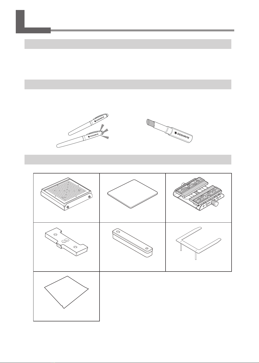
Checking the Included Items
This kit contains the following items. Make sure they are all present and accounted for.
Grid table (1) Adhesive sheet (1) Center vise (1)
Clamp plates (2) Base (1) Film frame (1)
Light-absorbing lm (yellow; 1)
Getting Started
Material Conditions
In order for a material to be used for imprinting, the material must meet all of the following conditions.
Material
• Acrylic
• Polypropylene
• Polystyrene
• ABS
• Leather
• Polyurethane
• Vinyl chloride
Thickness
Maximum: 26mm (1.02in.)
* Height from the base table to the upper surface of the material loaded on theVISE KIT: 50mm (1.96in.) or less
Size
The material is large enough to be rmly secured.
You can use the center vise or the adhesive sheet to secure the material. It is acceptable for the material to be
of a size such that it protrudes from the center vise or adhesive sheet, but the essential requirement is that
the material can be rmly secured.
Shape
There must be no unevenness on the imprint surface.
Imprinting is not possible for material that comes into contact with the moving part of the machine when
being loaded or during imprinting.
The edge of the material is too high.
NOT OK
L-shape
NOT OK
Gentle undulations of less than 0.5 mm (0.0196 in.).
Correct imprinting is not possible if the height displacement cannot be tracked by the head.
Cross-sectional view:
Flat view:
3

Getting Started
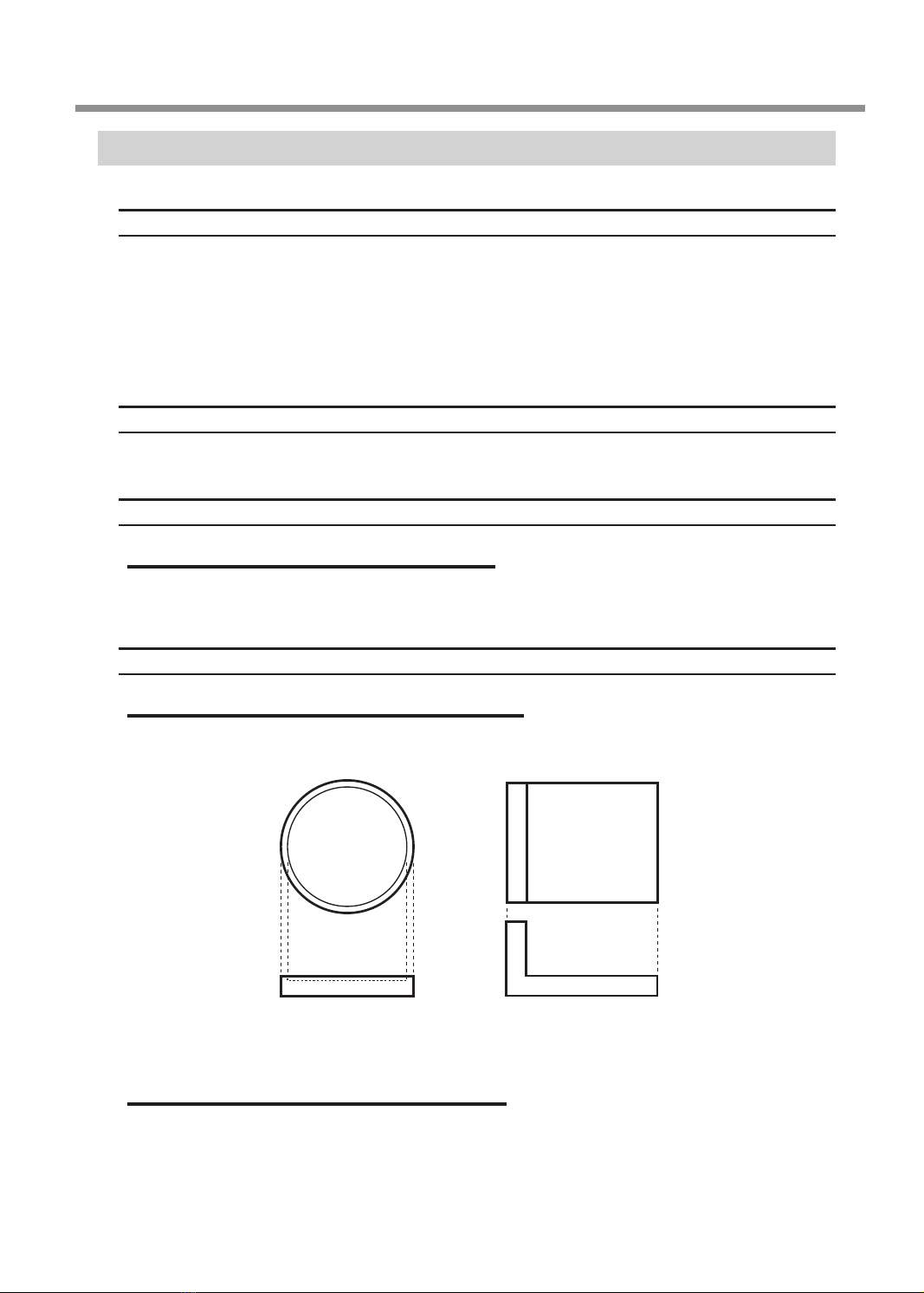
Conditions for Material When Imprinting Curved Surfaces
The table and gure below show the recommended imprint area with respect to the diameter of the cylinder
formed from an extended curved surface. Note, however, that the following conditions are assumed.
Material with an extended curved surface has circularity.
Diameter of cylinder with
extended curved surface (ø) Recommended imprint area (A)
10 mm (0.394 in.) 2.0 mm (0.078 in.)
20 mm (0.79 in.) 2.8 mm (0.11 in.)
30 mm (1.19 in.) 3.4 mm (0.133 in.)
4
Getting Started
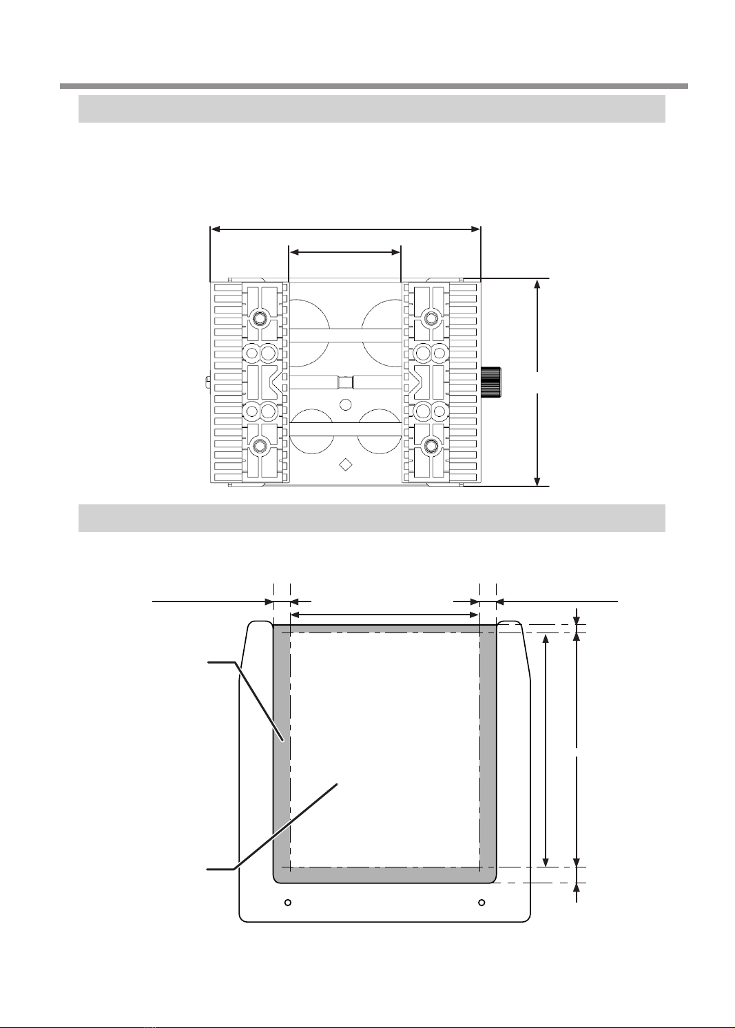
Center Vise Specications
The maximum width of loadable material is 50mm (1.96in.).
Change the loading orientation and secure the material in a way that matches its size.
You can vary the orientation and front and back sides of the vise when using it.
"P. 7 "How to Secure Material"
120 mm (4.7 in.)
50 mm (1.96 in.)
93.5 mm (3.68 in.)
Imprint Area
The following gure shows the imprint area of the light-absorbing lm. Imprinting within the unimprintable
area will lead to interference between the lm frame and the head, which may result in head damage.
11.1 mm (0.437 in.)
92.8 mm (3.65 in.)
11.1 mm (0.437 in.)
120 mm (4.7 in.)
3.5 mm (0.137 in.) 9.5 mm (0.374 in.)
Unimprintable area
Imprintable area
5
6
Vise Kit Explanation
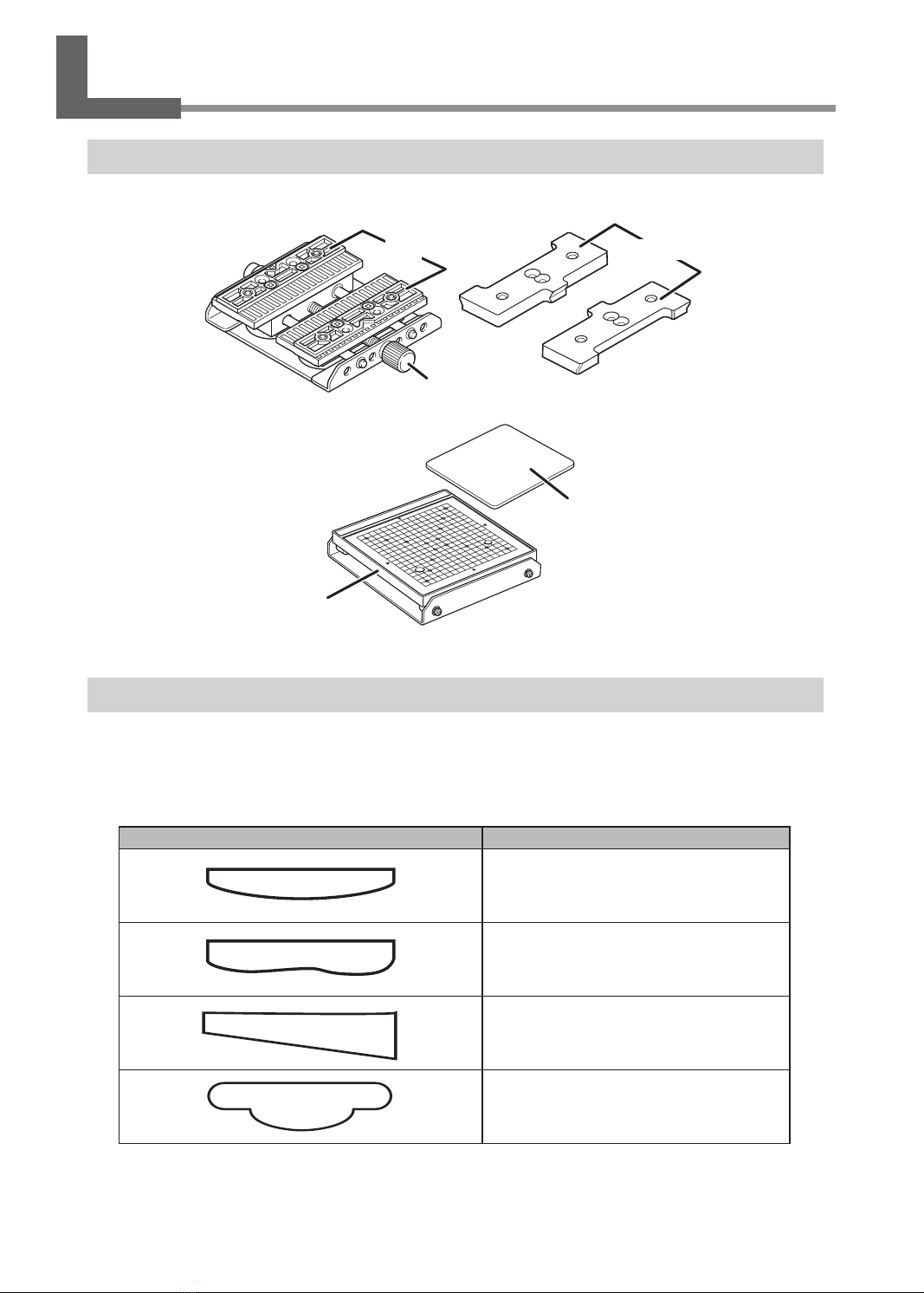
Material Retainer Types
Center vise
Retaining screw
Vise
Grid table
Grid table
Adhesive sheet
Selecting Material Retainers according to Material Shapes
Retainers have various characteristics. Select the retainer that matches the material shape.
The grid table is suited to securing material that has a at bottom surface. The center vise is suited to
securing material that has a curved bottom surface. Both retainers secure material so that the imprint surface
has gentle undulations of less than 0.5mm (0.0196in.).
The following table shows examples of material shape and retainer combinations.
Material shape Retainer
Vise
(center vise)
Vise
(center vise)
Vise
(center vise)
Clamp plates
(center vise)
Clamp plates

Vise Kit Explanation
Material shape Retainer
Clamp plates
(center vise)
"P. 4 "Conditions for Material When
Imprinting Curved Surfaces"
Grid table
Grid table
Grid table
How to Secure Material
Center vise
• Use the resin vise to clamp the material and secure it.
You can use the center vise to secure material that has a curved bottom surface. Clamp the material in
place in the vise, and then tighten the retaining screw enough to keep the material from easily coming
loose. Be careful not to overtighten, because doing so may damage the material.
Retaining screw
Vise
7
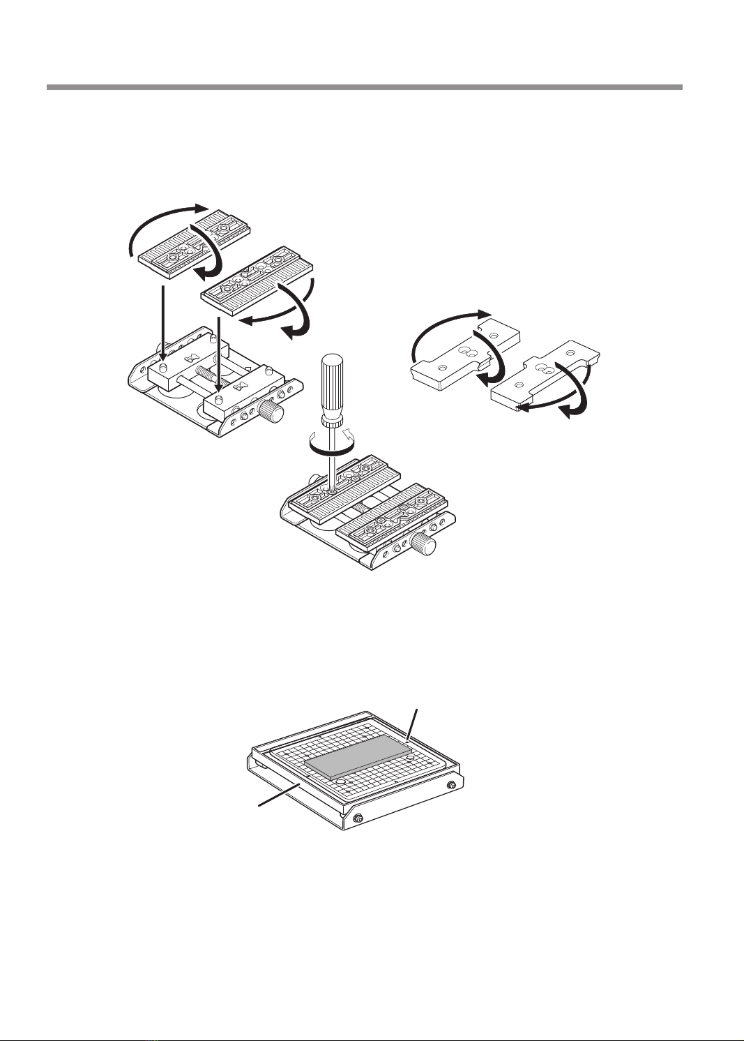
Vise Kit Explanation
• You can vary the orientation and front and back sides of the vise when using it.
Use the vise in a way that matches the size and shape of the material.
The vise can be replaced with clamp plates. You can also vary the orientation and front and back sides
of the clamp plates when using them.
This is suitable for clamping cylindrical material.
This is suitable for clamping plate-shaped material.
Grid table
• This is used to x material on a table.
Material is placed on the adhesive sheet, which then secures the material. This lets you secure objects
without having to use commercially available tape or the like.
Grid table
Adhesive sheet
8

Vise Kit Explanation
Light-absorbing Film
To use the light-absorbing lm, attach it to the lm frame.
A Orient the lm frame so that the adhesive sheet surface faces up.
B Peel the protective lm o the adhesive sheet.
C Ax the light-absorbing lm to the lm frame.
Important: The light-absorbing lm has a material side and a lens side. Afx it with the correct side facing up.
Attach the light-absorbing lm so that its notch is in the position shown in the following gure.
OK Not OK
Protective lm
9
Vise Kit Explanation
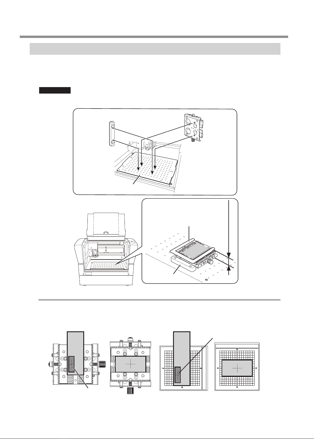
Mounting on the LD-300
Insert the protrusions on the bottom surface into the holes on the base table to attach the center vise or grid
table.
To attach the lm frame, insert its supports into the holes on the base.
Important
When not using the base, store it after removing it from the machine.
Center vise
or grid table
Base table
Important: Ensure that the height from the base table to the imprinting surface is 50 mm (1.96 in.) or less.
The center vise and grid table can be used vertically or horizontally. Select an appropriate orientation according
to the material size and the area to be imprinted.
Area to be imprinted
Area to be imprinted
Base
Film frame
Base
5
0 mm (1.96 in.) or less
10

Vise Kit Explanation
Selecting the Head Detection Jig
Use dierent head detection jigs depending on the height from the base table to the imprinting surface.
Important: Use the head detection jig with the correct height.
If you use the incorrect jig, the head will strike the material, leading to defective imprinting and part damage.
Height to the imprinting surface Head detection jig to use
24 to 36 mm
(0.95 to 1.42 in.)
Low
Higher than 36 mm
(1.42 in.) (*1)
High
*1: Imprinting is not possible if the height from the base table to the imprinting surface exceeds
50mm (1.96in.).
11

12
Daily Care
Cleaning the Center Vise/Grid Table
Using a cloth moistened with water and wrung well, wipe the parts gently to clean them.
Cleaning the Adhesive Sheet
Buildup of dust or the like on the grid table's adhesive sheet can reduce the sheet's adhesive force, making it
dicult to secure material. If the adhesive force has been reduced, wash the adhesive sheet.
Adhesive sheet
How to Wash the Adhesive Sheet
Immerse the adhesive sheet in water and wash the sheet by gently stroking its surface. If the soiling of the
adhesive sheet is severe, wash it using diluted neutral detergent. Rinse thoroughly with water to remove all
detergent.
Important
Observe the points below. Failing to do so may lead to damage to the surface of the adhesive sheet, thereby
lowering the adhesiveness.
• Never scrub the adhesive sheet using a scrubbing pad or sponge.
• Never stretch or bend the adhesive sheet when washing it.
How to Dry the Adhesive Sheet
Allow the adhesive sheet to dry completely while keeping it out of direct sunlight.

Daily Care
Cleaning the Film Frame
Buildup of dust or the like on the lm frame's adhesive sheet can reduce the sheet's adhesive force, making
it impossible to secure the light-absorbing lm. If the adhesive force has been reduced, wash the lm frame's
adhesive sheet.
How to Wash the Adhesive Sheet
Immerse the adhesive sheet in water and wash the sheet by gently stroking its surface. If the soiling of the
adhesive sheet is severe, wash it using diluted neutral detergent. Rinse thoroughly with water to remove all
detergent.
Important
Observe the points below. Failing to do so may lead to damage to the surface of the adhesive sheet, thereby
lowering the adhesiveness.
• Never scrub the adhesive sheet using a scrubbing pad or sponge.
• Never stretch or bend the adhesive sheet when washing it.
How to Dry the Adhesive Sheet
Allow the adhesive sheet to dry completely while keeping it out of direct sunlight.
Adhesive sheet
13

14
Location of Serial Number Label
Center Vise
Grid Table
Position where the label
is axed
Position where the label
is axed

R1-200608
FA02211
Table of contents
Other DGSHAPE Medical Equipment manuals


Popular Medical Equipment manuals by other brands


laerdal
laerdal LSR Adult user guide

Handicare
Handicare SystemRoMedic TurnSafe2 user manual

Topcon
Topcon 3D OCT-1 Quick reference guide

laerdal
laerdal Trauma Modules Directions for use

Ultimate Healthcare
Ultimate Healthcare Tamora Plus II user manual

Boston Scientific
Boston Scientific SC-2016 Series Directions for use


