DH PGI Series How to use

PGI Gripper
Short Manual
Content
Revisions...........................................................................................................................................1
1 Specifications.................................................................................................................................2
1.1 Indicator ..............................................................................................................................2
1.2 Pinout Description...............................................................................................................3
2 Modbus-RTU Control ....................................................................................................................4
2.1 Wiring .................................................................................................................................4
2.1.1 Debugging software instructions..............................................................................5
2.2 Default Communication Parameters ...................................................................................8
2.3 Modbus-RTU Description...................................................................................................9
2.3.1 RTU Framing ...........................................................................................................9
2.3.2 Supported Modbus Function Code...........................................................................9
2.3.3 Register Mapping.....................................................................................................9
2.3.4 Register Description...............................................................................................11
2.3.4.1 Initialization ................................................................................................11
2.3.4.2 Force............................................................................................................12
2.3.4.3 Position........................................................................................................12
2.3.4.4 Speed...........................................................................................................13
2.3.4.5 Initialization State .......................................................................................13
2.3.4.6 Gripper State ...............................................................................................14
2.3.4.7 Current Position ..........................................................................................14
2.3.4.8 Save Parameter............................................................................................15
2.3.4.9 Initialization Direction ................................................................................15
2.3.4.10 Slave Address............................................................................................16
2.3.4.11 Baud Rate ..................................................................................................16
2.3.4.12 Stop Bits....................................................................................................17
2.3.4.13 Parity .........................................................................................................17
2.3.4.14 Test I/O Parameters ...................................................................................18
2.3.4.15 I/O Mode Switch.......................................................................................18
2.3.4.16 I/O Parameter Configuration.....................................................................19
3 I/O Control...................................................................................................................................20
3.1 Wiring ...............................................................................................................................21
3.2 I/O Setting.........................................................................................................................21
3.2.1 Configure IO ..........................................................................................................22
3.2.2 Open IO..................................................................................................................23
3.2.3 Save Settings..........................................................................................................23
3.2.4. Restart ...................................................................................................................23

1
Revisions
Date
Version
Revised content
20200426
V1.0
First edition, write wiring instructions and
command instructions
20200904
V2.0
Change some instructions , Update the description
of IO mode

2
1 Specifications
PGI series are industrial electric gripper, The number(PGI-number) represents the maximum
gripping force of the gripper. The gripper is equipped with a pair of parallel fingertips, which runs
symmetrically during the movement. The main structure of the gripper is a smooth rectangular
structure. It is equipped with an 8-core communication interface, as shown in Figure 1.1. It has the
following characteristics:
Controllable force/position/speed: The gripper can program and adjust the grip position, grip
force and speed.
Multiple communication modes: The gripper supports Modbus RTU protocol and IO mode
control. Other communication protocols such as USB and ETHERNET can be transferred through
protocol converter.
Gripping Detection:The combination of force control and position control is adopted in the
gripping process.
Gripping feedback: The state of the gripper can be read by programming, and can also be judged
according to the indicator of the gripper.
Fingertips can be customized: Fingertips can be replaced according to situation, which is
suitable for precision machining, parts assembly, and other fields.
1.1 Indicator
The gripper can feed back the state of the gripper in real time. In addition to the command reading,
it can also be judged on the color of the indicator:
Color description of indicator
·Uninitialized state: Red light blinks, other lights are off.
·Initialized State: the blue light is always on, indicating that it is in the operable state.
·Received command state: the red light blink once quickly (because the blue light is
always on at this time, the gripper indicator light will looks like a purple light).
·Object Caught state: green light is always on, other lights are off.
·Object dropped state: green light blinking.
3
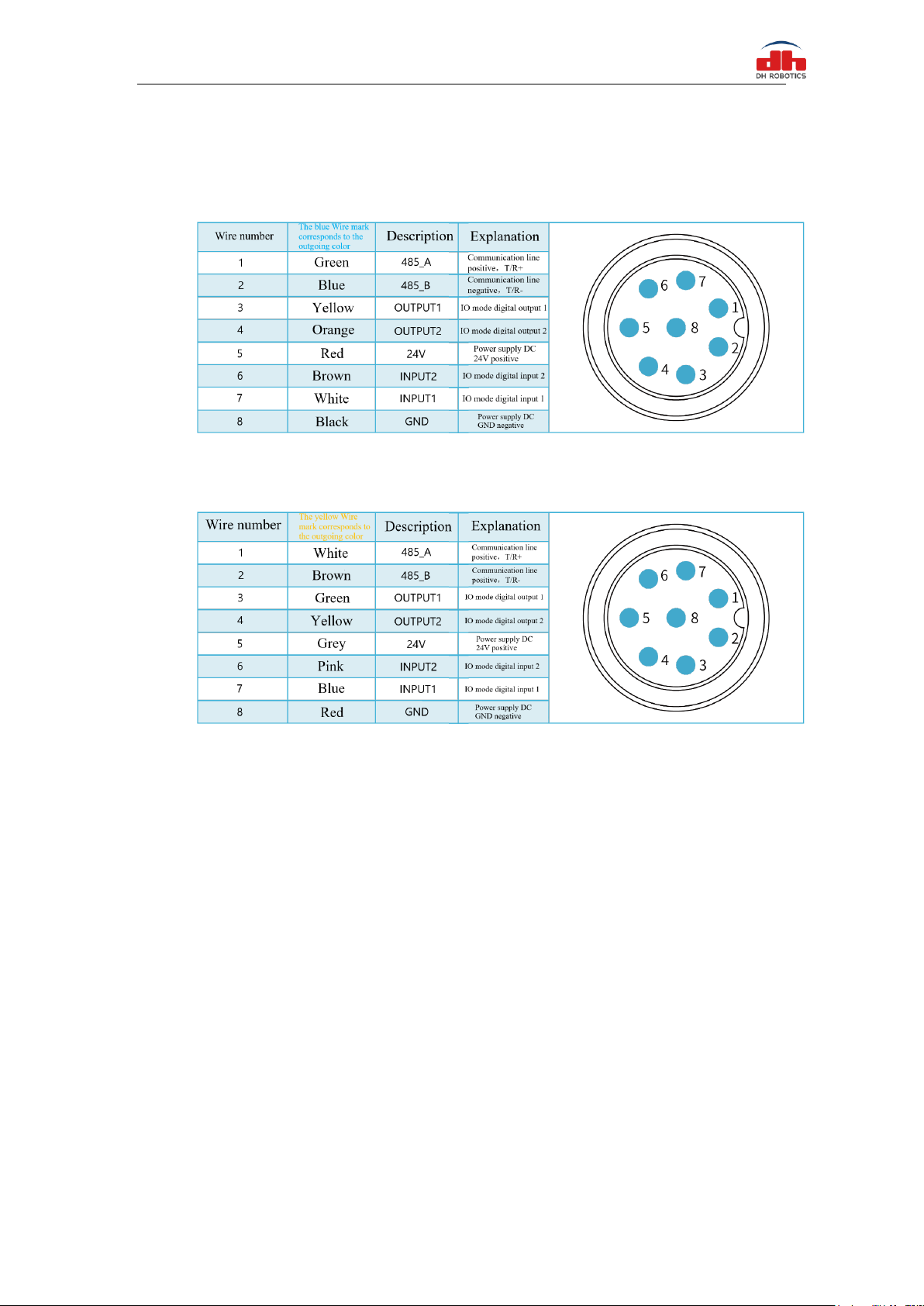
1.2 Pinout Description
The line sequence definition on the gripper body is shown in Figure 1.1(a) and 1.1(b)
Figure 1.1 (a) The blue line marked diagram
Figure 1.1 (b) The yellow line marked diagram
ote: Please distinguish the wire sequence according to the wire mark. If the wire mark is lost,
dropped, or forgotten, please contact our staff to cooperate in determining the wire
sequence. If you do not contact our staff, the clamping jaws will be damaged due to the
wrong wiring sequence, and you will be responsible for the consequences.
4
2 Modbus-RTU Control
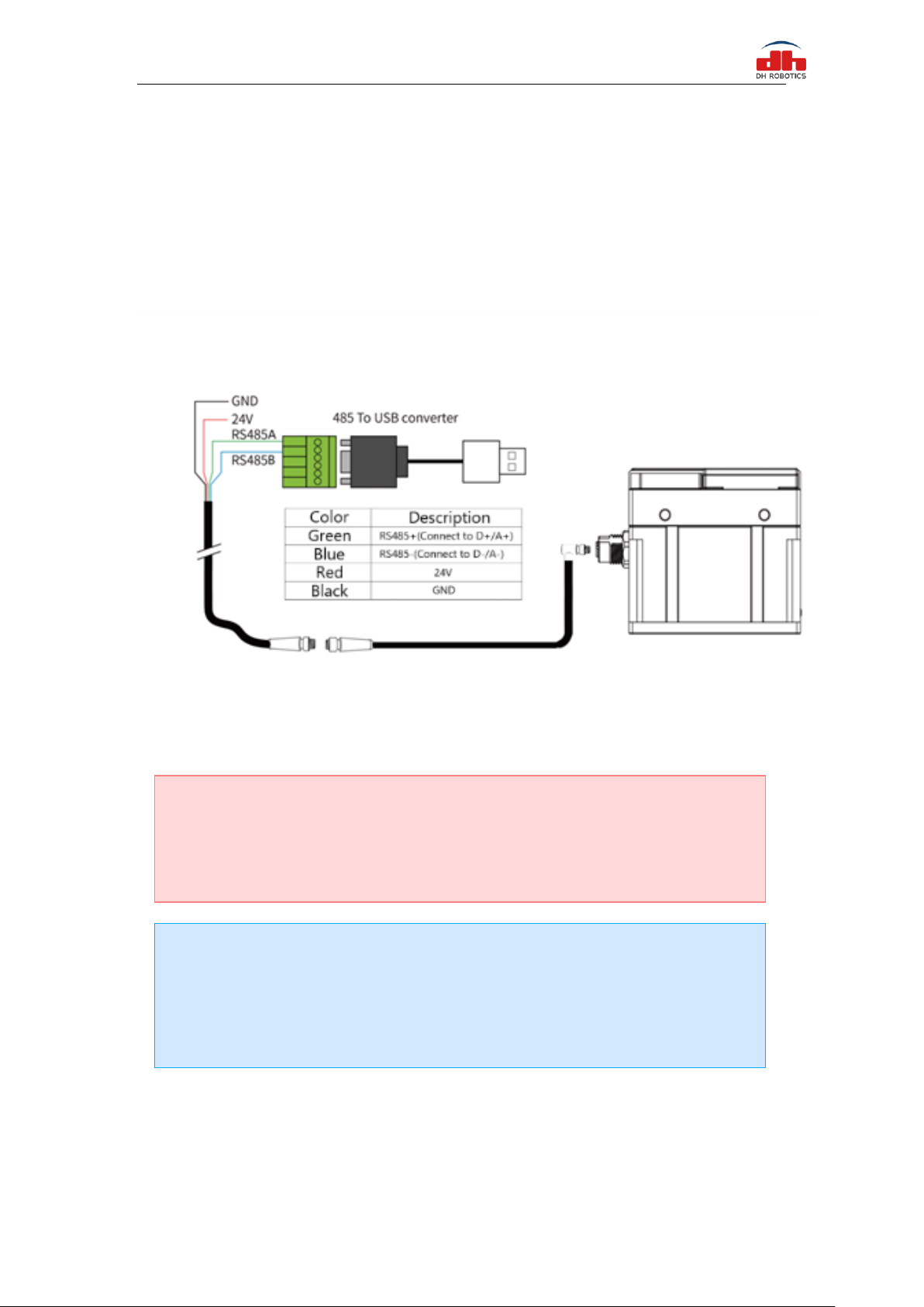
2.1 Wiring
Use the provided RS-485 to USB converter (see the schematic in Figure 1.1 below) to plug into a
PC or other Controllers.
Figure 2.1 RS485 Connection
Warning
·Please check the connector before inserting, and do not forcibly insert the plug. Even if
the cable connector has a fool-proofing design, but you can still forcibly insert it, then the
gripper would be damaged.
Wiring instructions
·① : when the device (computer) has RS485 interface, the communication can be directly
connected to RS485_A and RS485_B communication lines without transferring to 485
module through USB
·② : in this way, other serial port debugging software (such as MODBUS poll) can be
used for debugging
5
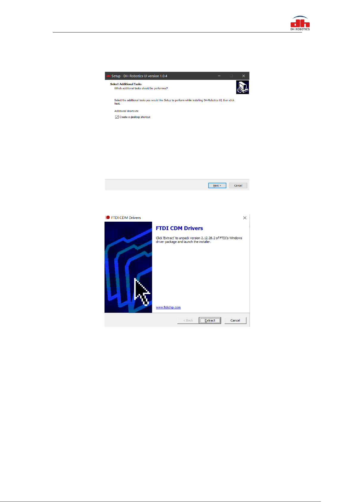
Software can be downloaded on the official website. Software and driver are integrated in the
process of software installation, and both are installed together. It is recommended to check the
create shortcut during installation.
Figure 2.2 (a) installation interface 1
Figure 2.2 (b) driver installation interface
2.1.1 Debugging software instructions
Before use, it is necessary to connect the corresponding wiring according to the instructions.
Open the software, the software will automatically identify the serial port, baud rate, ID number and
other information of the gripper for automatic connection. As shown in the figure below:
6
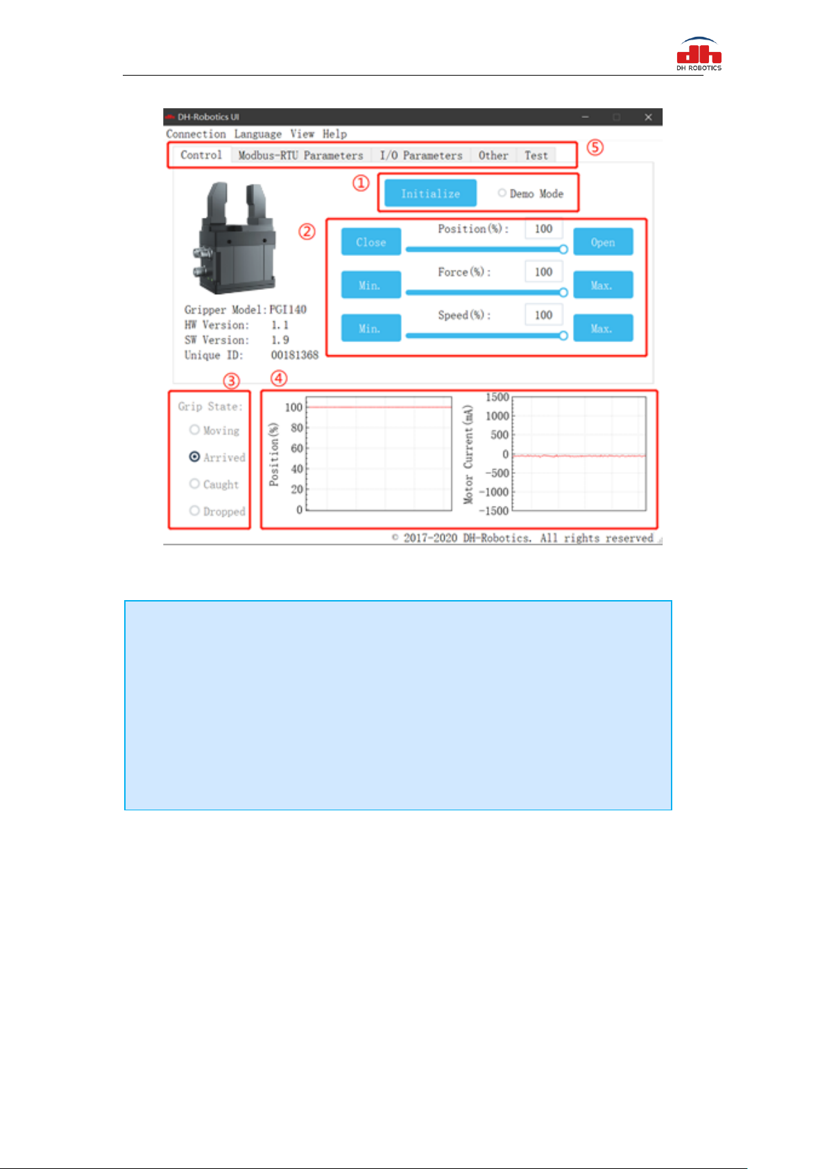
Figure 2.3 main control interface
The specific interface description is as follows:
The gripper body uses Modbus RTU for communication, and can read and write data into the
register. The data can be read and written at the view register. The data includes control, feedback,
user parameters and I/O parameters as shown in the following figure:
Interface description
·① Initialization and demonstration mode: the gripper needs to be initialized before
operation to calibrate the zero point. The demonstration mode is a cyclic program.
·② Control interface: it can control the position, force and speed of the gripper.
·③ Clamping status: real time display of clamping status of clamping claw.
·④ Position current real time graph: real time display position and current. The
current represents the current of the internal motor, not the current actually consumed by
the gripper. The current real-time graph can reflect the stability of clamping force.
·⑤ Parameter setting: the configuration parameters of Modbus RTU, such as baud rate
and check bit, can be configured; IO mode is to configure the parameters related to IO
mode;

7
Figure 2.4 View
If there are multiple 485 devices, sometimes the baud rate and ID number of the gripper need to be
modified, the parameters can be modified in Modbus RTU parameters
Figure 2.5 Modbus RTU parameters
You can set and configure the gripper I / O parameters in [I / O parameters]. After modifying the
parameters, please click Save button to save. The following figure shows the operation of opening
IO mode:

8
Figure 2.6 Modbus RTU parameters
The steps of switching IO are as follows:
2.2 Default Communication Parameters
Slave Address :1
Baud Rate :115200
Data Bits :8 bits
Stop Bits :1 stop bit
Parity :None
Steps to switch IO mode
·① Open IO mode: open IO mode first.
·② Configure four groups of IO parameters: set the four groups of parameters of
gripper, including position, force and speed.
·③ Save: click the Save button to write the parameters to the internal register of flash,
and restart to control.
·④ Restart: after the restart, the switch to IO mode is successful. You can control the
gripper according to the input signal, and the running status will be fed back through
output.

9
2.3 Modbus-RTU Description
2.3.1 RTU Framing
This gripper uses the standard Modbus-RTU protocol.
In RTU mode, the first field is the device address. The allowable characters transmitted for all
fields are hexadecimal 0 ... 9, A ... F. Networked devices monitor the network bus continuously,
including during the silent intervals. When the first field (the address field) is received, each
device decodes it to find out if it is the addressed device.
A typical message frame is shown in Table 2.1.
Table 2.1 RTU Framing (Function Code:0x06)
Slave Address
Function
Register address
Register data
CRC
01
06
01 00
00 01
49 F6
Slave Address: The Slave address of the gripper. The default is 1, you can also modify it through
write different value to Slave Address register.
Function: The Function Code field tells the addressed slave what function to perform. Includes read
or write registers function.
Register address: Specifies which registers reference to be written.
Register data: Specifies which value to be written. Each register (word - 16 bits) of the Modbus
RTU protocol is composed of 2 bytes (8 bits) from the Gripper.
CRC: the CRC error-checking field contains a 16-bit value implemented as two eight-bit bytes. The
CRC field is appended to the message as the last field in the frame. The low-order byte of the field
is appended first, followed by the high-order byte. The CRC high-order byte is the last byte to be
sent in the message.
2.3.2 Supported Modbus Function Code
This griper uses MODBUS- RTU. The following function codes are currently supported:
03 (HEX): Read Holding Registers
06 (HEX): Write Single Register
10 (HEX): Write Multiple Registers
2.3.3 Register Mapping
The gripper’s Modbus-RTU registers consist of two types of registers: the basic control registers
and the configuration registers.
Basic control registers: initialization, force setting, reference position, speed, and some states.

10
Configuration registers: gripper’s parameter configuration. Includes Modbus communication
parameters and I/O parameters.
Table 2.2 Basic Control register map
Function
high-
order
byte
low-
order
byte
Description
Write
Read
Initialization
0x01
0x00
Initialize the
gripper
0x01:initialization;
0xA5: Fully
initialization
Current setting
Force
0x01
Gripper’s
force
20-100 (%)
Force
currently set
Reserve
0x02
-
-
-
Position
0x03
Position
0-1000 (‰)
Reference position currently
set
Speed
0x04
Speed
1-100 (%)
Speed
currently set
Initialization
state
0x02
0x00
Initialization
state of the
gripper
Read Only
0:Not initialized;1:
Initialized
Gripper state
0x01
Gripper state
Read Only
0:In motion;
1:Reach position;
2 Object caught;
3:Object dropped
Position
0x02
gripper
position
Read Only
Current actual position
Table 2.3 Configuration register map
Function
High
byte
Low
bytes
Description
Write
Read
Save
Parameter
0x03
0x00
Save all the parameters
0:default,1:Write all
parameters to save
0
Initialization
direction
0x01
Configure
initialization direction
0: Open,1:Close
(default: 0)
Current setting
Slave Address
0x02
Configure gripper
Modbus address
0-255 (default: 1)
Current setting
Baud Rate
0x03
Configure gripper
Modbus Baud rate
0-5:115200,57600,
38400,19200,9600,
4800(default :0)
Current setting
Stop Bits
0x04
Configure gripper
Modbus stop bits
0:1 stop bit;
1:2 stop bits
(default: 0)
Current setting
Parity
0x05
Configure gripper
Modbus Parity
0: None parity;
1: Odd parity;
2: Even parity (default: 0)
Current setting
I/O Parameters
Test
0x04
0x00
Test I/O parameters
1;2;3;4
Current setting
I/O Mode
Switch
0x02
I/O control switch
0:OFF,1:ON
Current setting
I/O Parameter
Configuration
0x05-
0x10
Four groups of I/O
parameters
position 1,force 1,speed
1 to position 4,force 4,
speed 4
Current setting

11
2.3.4 Register Description
2.3.4.1 Initialization
This register is used to initialize the gripper.
Write: If write 1 (0x01 hex) to this register, the gripper will be initialized (fingers move to the
minimal or maximum position. The initialization direction depends on the value of initialization
direction register). If write 165 (0xA5 hex) to this register will fully initialize the gripper( find the
minimal and maximum position).
Read: if gripper need to be initialized or have initialized, this register value is 0; and if gripper is in
initializing process, this register value is 1.
The register address is 0x0100. The description of this register is shown in Table 2.4.
Table 2.4 Initialization
Function
Address
Description
Write
Read
Initialization
0x0100
Initialize the
gripper
0x01:initialize;
0xA5: Fully initialize
Current setting
The gripper needs to be initialized before control.
The sample command is as follows:
Initialize (write):
Send: 01 06 01 00 01 49 F6
Receive: 01 06 01 00 01 49 F6
Reinitialize(write):
Send:01 06 01 00 00 A5 48 4D
Receive: 01 06 01 00 00 A5 48 4D

12
2.3.4.2 Force
This register is used to set Force. It defines the current for the Gripper. If the current limit is exceeded,
the fingers stop and trigger an object detection.
The address is 0x0101. The description of this register is shown in Table 2.5.
Table 2.5 Force
Function
Address
Description
Write
Read
Force
0x0101
Gripper’s
closing force
20-100 (%)
Force
currently set
The force value range is 20-100, the corresponding value is 00 14–00 64(Hexadecimal).
Example:
Set 30% closing force (write):
Send: 01 06 01 01 1E 59 FE
Return: 01 06 01 01 1E 59 FE
Read the closing force currently set (read):
Send: 01 03 01 01 00 01 D4 36
Return: 01 03 02 xx xx crc1 crc2
2.3.4.3 Position
This register is used to set the reference position of gripper's fingers, then the fingers will move to
the position immediately.
The address is 0x0103. The description of this register is shown in Table 2.6.
Table 2.6 Position
Function
Address
Description
Write
Read
Position
0x0103
Reference
Position
0-1000 (‰)
Reference position
currently set
The reference position value range is 0-1000 (‰), the corresponding value is 00 00 – 03
E8(Hexadecimal).
Example:
Set 500‰position (write):
Send: 01 06 01 03 01 F4 78 21
Return: 01 06 01 03 01 F4 78 21
Read the reference position currently set(read):
Send: 01 03 01 03 00 01 75 F6
Return: 01 03 02 xx xx crc1 crc2

13
2.3.4.4 Speed
This register is used to set the Gripper closing and opening speed.
The address is 0x0102. The description of this register is shown in Table 2.7.
Table 2.7 Speed Instructions
Function
Address
Description
Write
Read
Speed
0x0104
Speed
1-100 (%)
Speed
currently set
The speed value range is 1-100 ,The corresponding value is 00 01 – 00 64(Hexadecimal).
Example:
Set 50% speed (write):
Send: 01 06 01 04 00 32 48 22
Return: 01 06 01 04 00 32 48 22
Read the current speed (read):
Send: 01 03 01 04 00 01 C4 37
Return: 01 03 02 xx xx crc1 crc2
2.3.4.5 Initialization State
This register is used to store current initialization state of gripper, you can get the initialization state
by reading this register.
The address is 0x0200. The description of this register is shown in Table 2.8.
Table 2.8 Initialization State
Function
Address
Description
Write
Read
Initialization
State
0x0200
Initialization state
of the gripper
Read Only
0:Not initialized;
1:Initialized
Example:
Read initialization state (read):
Send: 01 03 02 00 00 01 85 B2
Return: 01 03 02 00 00 B8 44

14
2.3.4.6 Gripper State
This register is used to store the Gripper state, you can get the state of gripper by reading this register.
And the address is 0x0201. The description of this register is shown in Table 2.9.
Table 2.9 Gripper State
Function
Address
Description
Write
Read
Gripper State
0x0201
the gripper state
Read
Only
0:In motion;
1:Reached position;
2:Object caught;
3:Object dropped
Example:
Read gripper state (read):
Send: 01 03 02 01 00 01 D4 72
Return: 01 03 02 00 02 39 85(02: object caught)
2.3.4.7 Current Position
This register is used to store the Actual position of the Gripper.
The address is 0x0202. The description of this register is shown in Table 2.10.
Table 2.10 Current Position
Function
Address
Description
Write
Read
Current Position
0x0202
Gripper actual position
Read Only
Current actual
position
Example:
Read actual position (read):
Send: 01 03 02 02 00 01 24 72
Return: 01 03 02 xx xx crc1 crc2
States Description
Different values indicate different states of the gripper. The descriptions of states are as
follows:
·00: Fingers are in motion .
·01: Fingers are at reference position. No object detected or object has been dropped.
·02: Fingers have stopped due to an object detection.
·03: Fingers are at reference positon due to object has been dropped after the gripper
caught object.

15
2.3.4.8 Save Parameter
This register is used to Save Parameter.
Write 1 to this register to save all parameter, If you modified the I/O or communication parameters.
The address is 0x0300. The description of this register is shown in Table 2.11.
Table 2.11 Save Parameter
Function
Address
Description
Write
Read
Save
Parameter
0x0300
Save register’s
value to Flash
0:default,
1:Save all parameters
0
Example:
Save Parameter (Write):
Send: 01 06 03 00 00 01 48 4E
Return: 01 06 03 00 00 01 48 4E
2.3.4.9 Initialization Direction
This register is used to set Initialization Direction of gripper.
The address is 0x0301. The description of this register is shown in Table 2.12.
Table 2.12 Baud Rate
Function
Address
Description
Write
Read
Baud Rate
0x0301
Configure
initialization
direction
0: Open,1:Close
(default: 0)
Current setting
The value of this register is 0 by default.
If the register value is 0, when you send the initialization command, the gripper finger will open and
find the maximum position.
If the register value is 1, when you send the initialization command, the gripper finger will close
and find the minimal position.
Example:
Write 0 to initialization direction register:
Send: 01 06 03 01 00 00 D8 4E
Return: 01 06 03 01 00 00 D8 4E
NOTE
·The Saving process will take 1-2 seconds, and the gripper won’t response to other
command during this process. The gripper will response this command after saving process
finished.

16
2.3.4.10 Slave Address
This register is used to set Slave Address of gripper.
The address is 0x0302. The description of this register is shown in Table 2.13.
Table 2.13 Slave Address
Function
Address
Description
Write
Read
Slave Address
0x0302
Configure gripper
Slave Address
0-255 (default: 1)
Current setting
The value of this register is 1 by default.
Example:
Set the Slave Address to 1(write):
Send: 01 06 03 02 00 01 E9 8E
Return: 01 06 03 02 00 01 E9 8E
2.3.4.11 Baud Rate
This register is used to set Baud Rate of gripper.
The address is 0x0303. The description of this register is shown in Table 2.14.
Table 2.14 Baud Rate
Function
Address
Description
Write
Read
Baud Rate
0x0303
Configure gripper
Modbus Baud rate
0-5:115200,57600,
38400,19200,9600,
4800(default: 0)
Current setting
The value of this register is 0 by default, corresponding to a baud rate of 115200.
Example:
Set gripper baud rate to115200 (write):
Send: 01 06 03 03 00 00 79 8E
Return: 01 06 03 03 00 00 79 8E
NOTE
·Please make sure that no other networked device has the same slave address as the
gripper.

17
2.3.4.12 Stop Bits
This register is used to set Stop Bits of gripper.
The address is 0x0302. The description of this register is shown in Table 2.15.
Table 2.15 Stop bits settings
Function
Address
Description
Write
Read
Stop Bits
0x0304
Configure gripper
Modbus stop bits
0:1 stop bit
1:2 stop bits
(default: 0)
Current setting
The value of this register is 0 by default, corresponding to 1 stop bit.
Example:
Set the gripper stop bit to 1 stop bit (write):
Send: 01 06 03 04 00 00 C8 4F
Return: 01 06 03 04 00 00 C8 4F
2.3.4.13 Parity
This register is used to set Parity of gripper.
The address is 0x0305. The description of this register is shown in Table 2.16.
Table 2.16 Parity
Function
Address
Description
Write
Read
Parity
0x0305
Configure
gripper Modbus
Parity
0: None Parity
1: Odd Parity
2: Even Parity
(default : 0)
Current setting
The value of this register is 0 by default, corresponding to None Parity.
Example:
Set the gripper’s Parity to None Parity (write):
Send: 01 06 03 05 00 00 99 8F
Return: 01 06 03 05 00 00 99 8F

18
2.3.4.14 Test I/O Parameters
This register is used to test the I/O Parameters.
The address is 0x0400. The description of this register is shown in Table 2.17.
Table 2.17 I/O Control
Function
Address
Description
Write
Read
Test I/O
Parameters
0x0400
Test I/O
Parameters
1;2;3;4
Current setting
This register can be used to directly test 4 groups of I/O parameters through Modbus-RTU to ensure
that the I/Oparameters are appropriate. For example,Write 1 to this register, the gripper will execute
action with the first group of I/O parameter.
Example:
Control gripper by using first group of I/O parameter (write):
Send: 01 06 04 00 00 01 49 3A
Return: 01 06 04 00 00 01 49 3A
2.3.4.15 I/O Mode Switch
This register is used to turn I/O Control Mode ON or OFF.
The address is 0x0402. The description of this register is shown in Table 2.18.
Table 2.18 I/O Mode Switch
Function
Address
Description
Write
Read
I/O Mode
Switch
0x0402
I/O Control
Switch
0:OFF,1:ON
Current setting
If you have written 1 to this register and have saved all parameters, the gripper will be initialized
automatically after power on.
When the I/O Control Mode is turned on, the gripper can respond to Modbus-RTU commands and
I/O, but I/O has priority.
The control method in different mode is shown in Table 2.19.
Table 2.19 Control method
Switch State
Description
Modbus-RTU
I/O
0
I/O control mode off
YES
No
1
I/O control mode on
YES
YES
Example:
Set the I/O control mode switch off (write):
Send: 01 06 04 02 00 00 29 3A
Return: 01 06 04 02 00 00 29 3A

19
2.3.4.16 I/O Parameter Configuration
Those registers are used to Set the I/O Parameters.
The address is 0x0405-0x0410. The description of this register is shown in Table 2.20.
Table 2.20 I/O Parameter Configuration
Function
High-
byte
Low
bytes
Description
Write
Read
I/O Group 1
0x04
0x05
position 1
0-1000‰
Current setting
0x06
force 1
20-100 %
0x07
speed 1
1-100 %
I/O Group 2
0x08
position 2
0-1000‰
0x09
force 2
20-100 %
0x0A
speed 2
1-100 %
I/O Group 3
0x0B
position 3
0-1000‰
0x0C
force 3
20-100 %
0x0D
speed 3
1-100 %
I/O Group 4
0x0E
position 4
0-1000‰
0x0F
force 4
20-100 %
0x10
speed 4
1-100 %
Example:
Set the first group of I/O parameter (write) :
Send: 01 06 04 05 01 2C 98 B6 (Reference position: 300‰)
Return: 01 06 04 05 01 2C 98 B6
Send: 01 06 04 06 00 1E E8 F3 (Force: 30%))
Return: 01 06 04 06 00 1E E8 F3
Send: 01 06 04 07 00 1E B9 33 (Speed: 30%)
Return: 01 06 04 07 00 1E B9 33
IO parameter address is continuous address, and four groups of IO parameters can be configured
at one time by using the function code of 0x10, as follows:
Continuous multiple address write(write)[Group 1:1000‰position;20%force;10%speed Group
2:100‰position;20%force;2%speed Group 3:0‰position;100%force;5%speed Group 4:592‰
position;100%force;10%speed]:
Send: 01 10 0405 000C 18 03e8 0014 000A 0100 0014 0002 0000 0064 0005 0250 0064
000a 9f 44
Return: 01 10 04 05 00 0C D1 3D
NOTE
·If you just need to control the gripper through Modbus RTU, you should write 0 to this
register and save all parameters to turn off the I/O control mode.
Table of contents
Other DH Industrial Equipment manuals


Popular Industrial Equipment manuals by other brands


matev
matev FPS JD-2026R operating manual

ITW Dynatec
ITW Dynatec DYNAMINI 4-HOSE Technical documentation

Festo
Festo MPS 200 operating instructions

weha
weha Transport rack for kitchen tops quick start guide

Voltaire
Voltaire 15W/F Installation, operation and maintenance manual

SAF-HOLLAND
SAF-HOLLAND Holland DB-040DQ1 owner's manual