SAF-HOLLAND Holland DB-040DQ1 User manual

Owner’s Manual
Forged Steel Drawbar
with 4-bolt Mounting Base
Installation, Operation and Maintenance Procedures
For on/off-road applications
Weight: DB-040DQ1 (approx.) 14 lbs. (6.35 kg)
DB-060FQ1 (approx.) 19 lbs. (8.62 kg)
DB-100FQ1 (approx.) 19 lbs. (8.62 kg)
XL-DB20009UM-en-US Rev –
DB-100FQ1
7/8" Bolts
DB-060FQ1
3/4" Bolts
DB-040DQ1
5/8" Bolts
For Load Ratings, Refer to Section 3

2XL-DB20009UM-en-US Rev – · 2015-07-29 · Amendments and Errors Reserved · © SAF-HOLLAND, Inc., SAF-HOLLAND, HOLLAND, SAF,
and logos are trademarks of SAF-HOLLAND S.A., SAF-HOLLAND GmbH, and SAF-HOLLAND, Inc.
Contents
Contents Page
Introduction...............................................2
Warranty....................................................2
Notes, Cautions, and Warnings...................2
Section 1 –General Safety Instructions .....3
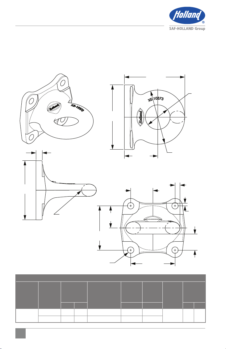
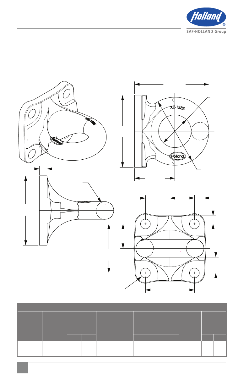
Section 2 –Drawbar Eye Dimensions......... 4
Section 3 –Load Ratings............................7
Contents Page
Section 4 –Towing Applications ................7
Section 5 –General Information................. 7
Section 6 –General Safety Information ..... 7
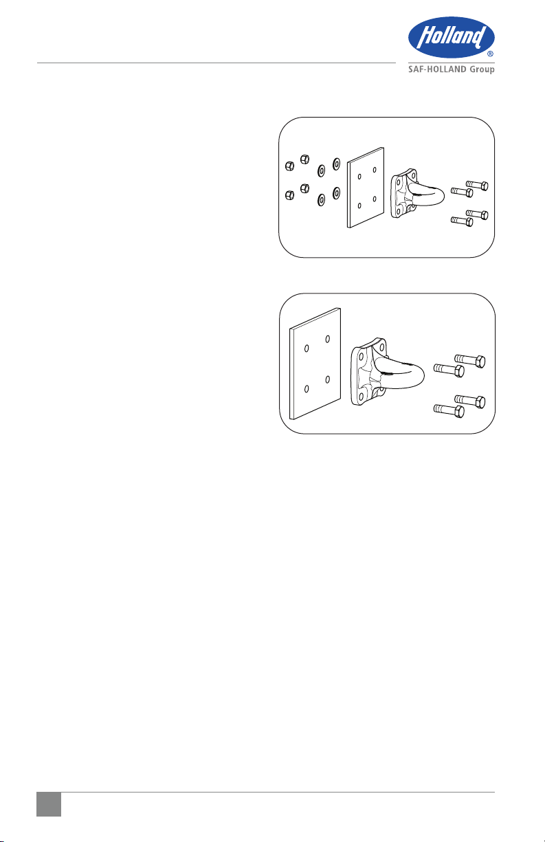
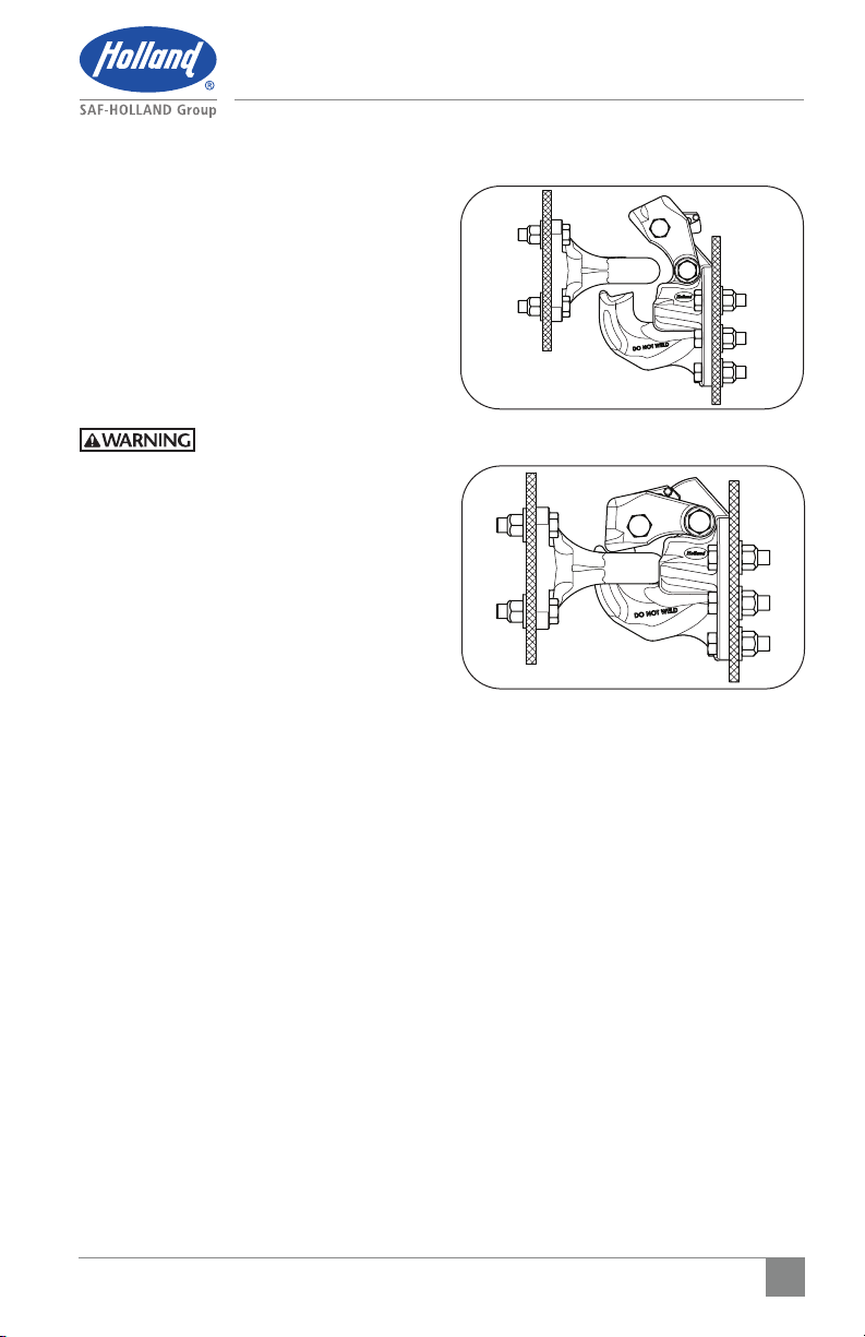
Section 7 –Mounting Instruction ..............8
Section 8 – Operating Instructions ............9
Section 9 – Maintenance......................... 10
Introduction
This manual provides information necessary
for the proper operation, maintenance, and
inspection of the SAF-HOLLAND®drawbar.
NOTE: For HOLLAND®replacement
components contact
SAF-HOLLAND®Customer
Service: 1-888-396-6501.
Warranty
Refer to the complete warranty for the
country in which the product will be used.
A copy of the written warranty can be
downloaded from our SAF-HOLLAND®
website (www.safholland.com).
Notes, Cautions, and Warnings
Read and understand all of the procedures
presented in this manual before starting
any work on the pintle hook.
NOTE: In the United States, work shop
safety requirements are defined by
federal and/or state Occupational
Safety and Health Act. Equivalent
laws could exist in other countries.
This manual is written based
on the assumption that OSHA or
other applicable employee safety
regulations are followed by the
location where work is performed.
Proper tools MUST be used to perform the
mounting and maintenance procedures
described in this manual.
This manual contains the terms “NOTE”,
“IMPORTANT”, “CAUTION”, and “WARNING”
followed by important product information.
These terms are defined as follows:
NOTE: Includes additional information
to enable accurate and easy
performance of procedures.
IMPORTANT: Includes additional
information that if
NOT followed could
lead to hindered
product performance.
Used without the safety alert
symbol, indicates a potentially
hazardous situation which,
if not avoided, could result
in property damage.
Indicates a potentially
hazardous situation which,
if not avoided, could result
in minor or moderate injury.
Indicates a potentially
hazardous situation which,
if not avoided, could result
in death or serious injury.

3
XL-DB20009UM-en-US Rev – · 2015-07-29 · Amendments and Errors Reserved · © SAF-HOLLAND, Inc., SAF-HOLLAND, HOLLAND, SAF,
and logos are trademarks of SAF-HOLLAND S.A., SAF-HOLLAND GmbH, and SAF-HOLLAND, Inc.
General Safety Instructions
1. General Safety Instructions
IMPORTANT: Read this manual before
using this product.
Keep this manual in
a safe location for
future reference.
Failure to follow the
instructions and safety
precautions in this manual
can result in equipment
failure which, if not
avoided, could result in
death or serious injury.
Read and observe all warning and caution
hazard alert messages in this publication.
The information provided can help prevent
death, serious injury and/or damage
to components.
NOTE: In this manual, all descriptions
of orientation are relative to
the vehicle.
FRONT
REAR
Orientation

4XL-DB20009UM-en-US Rev – · 2015-07-29 · Amendments and Errors Reserved · © SAF-HOLLAND, Inc., SAF-HOLLAND, HOLLAND, SAF,
and logos are trademarks of SAF-HOLLAND S.A., SAF-HOLLAND GmbH, and SAF-HOLLAND, Inc.
Dimensions
DB-040DQ1 2.5" (63.5 mm) I.D.
PART
NUMBER
RIGID
TONGUE
TRAILERS
CAPACITIES
WEIGHT HINGED TONGUE
MOUNT TRAILERS
CAPACITIES
MAX
VERTICAL
MAX
VERTICAL GRADE 8
FASTENER
SIZE
WEIGHT
LB. KG. LB. KG. LB. KG.
DB-040DQ1
2.5"
(63.5 mm) I.D.
GTW 40,000 18,144 GTW 60,000 27,216 5/8" 14 6.4
VERTICAL 8,000 3,629 VERTICAL 500 227
0.63"
(16.0 mm)
6.13"
(155.7 mm)
Ø2.50"
(63.5 mm)
Ø5.50"
(139.7 mm)
3.38"
(85.9 mm)
6.56"
(166.7 mm)
1.25" (31.8 mm)
x 1.5" (38.1 mm)
DIAMETER
6.00"
(152.4 mm)2.25"
(57.2 mm)
2.25"
(57.2 mm)
4.50"
(114.3 mm)
4.50"
(114.3 mm)
4 x Ø.656"(16.66 mm)
THROUGH HOLES
1.63"
(41.3 mm)
0.25"
(6.4 mm)
0.50"
(12.7 mm)
2. Drawbar Eye Dimensions
2.1 DB-040DQ1
2.5" (63.5 mm) I.D. with a 1.25" (31.8 mm)
x 1.5" (38.1 mm) diameter cross section.

5
XL-DB20009UM-en-US Rev – · 2015-07-29 · Amendments and Errors Reserved · © SAF-HOLLAND, Inc., SAF-HOLLAND, HOLLAND, SAF,
and logos are trademarks of SAF-HOLLAND S.A., SAF-HOLLAND GmbH, and SAF-HOLLAND, Inc.
Dimensions
0.71"
(17.9 mm)
6.83"
(173.4 mm)
6.61"
(168.0 mm)
3.71"
(94.1 mm)
2.25"
(57.2 mm)
1.44"
(36.6 mm)
0.75"
(19.1 mm)
0.87"
(22.1 mm)
4.50"
(114.3 mm)
4.50"
(114.3 mm)
2.25"
(57.2 mm)
Ø6.24"
(158.5 mm)
Ø3.00"
(76.2 mm)
Ø1.63"
(41.3 mm)
6.39"
(162.1 mm)
2.2 DB-060FQ1
3.0" (76.2 mm) I.D. with a 1.63" (41.3 mm)
diameter cross section.
4 x Ø.78" (19.8 mm)
THROUGH HOLES
DB-060FQ1 3.0" (76.2 mm) I.D.
PART
NUMBER
RIGID
TONGUE
TRAILERS
CAPACITIES
WEIGHT HINGED TONGUE
MOUNT TRAILERS
CAPACITIES
MAX
VERTICAL
MAX
VERTICAL GRADE 8
FASTENER
SIZE
WEIGHT
LB. KG. LB. KG. LB. KG.
DB-060FQ1
3.0"
(76.2 mm) I.D.
GTW 60,000 27,217 GTW 90,000 40,824 3/4" 19 8.6
VERTICAL 15,000 6,804 VERTICAL 500 227

6XL-DB20009UM-en-US Rev – · 2015-07-29 · Amendments and Errors Reserved · © SAF-HOLLAND, Inc., SAF-HOLLAND, HOLLAND, SAF,
and logos are trademarks of SAF-HOLLAND S.A., SAF-HOLLAND GmbH, and SAF-HOLLAND, Inc.
Dimensions
2.3 DB-100FQ1
3.0" (76.2 mm) I.D. with a 1.63" (41.3 mm)
diameter cross section.
0.71"
(17.9 mm)
6.83"
(173.4 mm)
6.61"
(168.0 mm)
3.71"
(94.1 mm)
2.25"
(57.2 mm)
1.44"
(36.6 mm)
0.75"
(19.1 mm)
0.87"
(22.1 mm)
4.50"
(114.3 mm)
4.50"
(114.3 mm)
2.25"
(57.2 mm)
Ø6.24"
(158.5 mm)
Ø3.00"
(76.2 mm)
Ø1.63"
(41.3 mm)
6.39"
(162.1 mm)
4 x Ø.91" (23.0 mm)
THROUGH HOLES
DB-100FQ1 3.0" (76.2 mm) I.D.
PART
NUMBER
RIGID
TONGUE
TRAILERS
CAPACITIES
WEIGHT HINGED TONGUE
MOUNT TRAILERS
CAPACITIES
MAX
VERTICAL
MAX
VERTICAL GRADE 8
FASTENER
SIZE
WEIGHT
LB. KG. LB. KG. LB. KG.
DB-100FQ1
3.0"
(76.2 mm) I.D.
GTW 100,000 45,360 GTW 125,000 56,700 7/8" 19 8.6
VERTICAL 20,000 9,072 VERTICAL 500 227

7
XL-DB20009UM-en-US Rev – · 2015-07-29 · Amendments and Errors Reserved · © SAF-HOLLAND, Inc., SAF-HOLLAND, HOLLAND, SAF,
and logos are trademarks of SAF-HOLLAND S.A., SAF-HOLLAND GmbH, and SAF-HOLLAND, Inc.
Ratings, SAE and General Information
3. Load Ratings
This product meets or exceeds the testing
requirements for SAE J847 Type II Loads.
For Load Ratings Refer to Table on Pages 4-6.
4. Towing Applications
For general on/off road towing. For severe
off-road applications, reduce the above
capacities by 25%.
IMPORTANT: Off-road refers to terrain
on which a tow/towed
vehicle will operate
that is ungraded, rough
or undulating, with no
maintained travel surface,
generally considered to
NOT be part of the public
road system. Examples
include agricultural fields,
construction sites, utility
right-of-way, temporary
logging roads, and what
is commonly referred to
as 'two-track' roads.
5. General Information
1. DO NOT modify or add to the product.
2. This product is covered by
SAF-HOLLAND’S®Commercial
Warranty. SAF-HOLLAND®reserves
the right, without giving prior notice,
to change specifications and dimensions
as are altered or improved.
3. Inspect the coupling device on the tow
vehicle and trailer for proper operation.
DO NOT use any coupling device that
DOES NOT operate properly.
4. It is the responsibility of the user to
become familiar with coupling and
uncoupling procedures that are provided
by various governments, industry
associations and mating component
manufacturers instructions.
6. General Safety Information
This equipment MUST NOT be used in a
careless manner.
During Operation:
1. Maintain adequate vertical (tongue)
load to properly control the towed unit
(generally 10% of maximum GTW) but
DO NOT exceed the rated capacities.
2. DO NOT damage the coupling
components. Be particularly careful
during coupling and uncoupling.
3. NEVER strike any part of the item with
a steel hammer.

8XL-DB20009UM-en-US Rev – · 2015-07-29 · Amendments and Errors Reserved · © SAF-HOLLAND, Inc., SAF-HOLLAND, HOLLAND, SAF,
and logos are trademarks of SAF-HOLLAND S.A., SAF-HOLLAND GmbH, and SAF-HOLLAND, Inc.
Mounting Instructions
Figure 2
Figure 1
7. Mounting Instructions
1. Use a mounting structure of sufficient
strength to support the rated capacity
of the drawbar in accordance with SAE
J849 and SAE J847 respectively.
2. Install the drawbar in compliance
with all federal, state or local agency
regulations or laws governing the
installation and use of the product.
Consult with these agencies prior to
installation or use.
3. For bolt holes and mounting clearance
area. Refer to Dimensions, Pgs. 4-6.
4. Bolt sizes are as follows:
DB-040DQ1: 5/8" Grade 8 Bolts
DB-060FQ1: 3/4" Grade 8 Bolts
DB-100FQ1: 7/8" Grade 8 Bolts
5. Installation methods are as follows:
a. Through-bolt to the
mounting structure:
Insert and tighten four (4)new
Grade 8 bolts, ASTM Grade
C lock nuts, and hardened
washers (Figure 1).
b. Direct bolt to drilled and tapped
mounting structure. Refer to
section 7, step 1:
Apply nonpermanent thread
lock compound Loctite #242
or equivalent to four (4) new
Grade 8 bolts (Figure 2).
6. Properly tighten the mounting fasteners.
The recommended minimum torque is
as follows:
DB-040DQ1: 125 ft-lbs. (169.5 N•m)
DB-060FQ1: 282 ft-lbs. (382.3 N•m)
DB-100FQ1: 454 ft-lbs. (615.5 N•m)

9
XL-DB20009UM-en-US Rev – · 2015-07-29 · Amendments and Errors Reserved · © SAF-HOLLAND, Inc., SAF-HOLLAND, HOLLAND, SAF,
and logos are trademarks of SAF-HOLLAND S.A., SAF-HOLLAND GmbH, and SAF-HOLLAND, Inc.
Operating Instructions
Figure 4
Figure 3
8. Operating Instructions
1. Before operating, inspect for wear,
damaged, or missing parts and a
secure mount. Correct as required
before use.
2. Position the drawbar eye over the
horn of the pintle and lower into place
(Figure 3 and 4).
3. Engage the drawbar with the coupling
device per the manufacturers instructions.
Failure to correctly secure
the drawbar can result in
separation of the trailer,
which, if not avoided,
could result in death or
serious injury.

10 XL-DB20009UM-en-US Rev – · 2015-07-29 · Amendments and Errors Reserved · © SAF-HOLLAND, Inc., SAF-HOLLAND, HOLLAND, SAF,
and logos are trademarks of SAF-HOLLAND S.A., SAF-HOLLAND GmbH, and SAF-HOLLAND, Inc.
Maintenance
9. Maintenance
For proper performance, the following
maintenance steps should be performed
every 30,000 miles (48,280 km) or three
(3) months, whichever comes first.
Failure to inspect and
maintain the drawbar may
result in separation of the
pintle hook and drawbar,
which, if not avoided,
could result in death or
serious injury.
1. Clean and check for wear, damaged,
or missing parts, and a secure mount.
Inspect for worn, damaged or missing
parts. Replace as required using only
Genuine SAF-HOLLAND®parts.
2. Inspect, in particular, the coupling
contact area of the drawbar. Inspect
for any nicks, gouges and deformation,
which may interfere with or affect the
safe use of the drawbar. If cracks are
visible, replace.
3. Using calipers or the SAF-HOLLAND®
drawbar gauges TF-11887, measure
the cross section of the drawbar eye.
Replace the complete product when
wear exceeds 0.125" (3.18 mm) from
the original surface profile. For original
profile dimension (Refer to Section 2,
page 4 Dimensions).
4. Inspect the drawbar fasteners. For bolted
connections refer to proper torque in
Section 7. In addition to being a safety
hazard, a loose drawbar will cause
excessive "chucking" and rapid wear.
Reinstall or replace any drawbar which
is NOT securely mounted.

11
XL-DB20009UM-en-US Rev – · 2015-07-29 · Amendments and Errors Reserved · © SAF-HOLLAND, Inc., SAF-HOLLAND, HOLLAND, SAF,
and logos are trademarks of SAF-HOLLAND S.A., SAF-HOLLAND GmbH, and SAF-HOLLAND, Inc.
Notes

From fifth wheel rebuild kits to suspension bushing repair
kits, SAF-HOLLAND Original Parts are the same quality
components used in the original component assembly.
SAF-HOLLAND Original Parts are tested and designed to
provide maximum performance and durability. Will-fits,
look-alikes or, worse yet, counterfeit parts will only limit
the performance potential and could possibly void
SAF-HOLLAND’s warranty. Always be sure to spec
SAF-HOLLAND Original Parts when servicing your
SAF-HOLLAND product.
SAF-HOLLAND USA, INC.
1950 Industrial Blvd., Muskegon, MI 49443
www.safholland.com
XL-DB20009UM-en-US Rev – · 2015-07-29 · Amendments and Errors Reserved · © SAF-HOLLAND, Inc., SAF-HOLLAND, HOLLAND, SAF, and logos are trademarks of SAF-HOLLAND S.A., SAF-HOLLAND GmbH, and SAF-HOLLAND, Inc.
SAF-HOLLAND USA · 888.396.6501 · Fax 800.356.3929
www.safholland.us
SAF-HOLLAND CANADA · 519.537.3494 · Fax 800.565.7753
WESTERN CANADA · 604.574.7491 · Fax 604.574.0244
www.safholland.ca
SAF-HOLLAND MEXICO · 52.1.55.5456.8641 · Fax 52.55.58162230
www.safholland.com.mx
This manual suits for next models
2
Table of contents
Other SAF-HOLLAND Industrial Equipment manuals