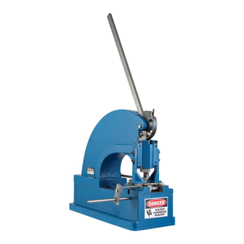
Di-Acro 36 User manual

MODEL 36
MODEL 36
Di-Acro
Di-Acro
Hand Shear
Hand Shear
OPERATOR’S MANUAL & INSTRUCTIONS
Di-Acro, Incorporated
PO Box 9700
Canton, Ohio 44711
3713 P og ess St eet N.E.
Canton, Ohio 44705
330-455-1942
330-455-0220 (fax)
Revised 01/02
Sale o dist ibution of manuals is st ictly p ohibited
without the exp ess w itten consent of Di-Ac o, Inco po ated

Installation and Setup 1. Bolt the shea to a flat su face such
as a wo kbench o stand. If the su face
is not level, it may be necessa y to
place shims unde one of the mounting
flanges on the shea base. Be ce tain
that the mounting bench o stand is
secu ely bolted to the floo to p event
tipping.
2. Inse t the shea handle (A) into the
holde (B) and secu e with sc ew.
Handle holde may be moved to the
opposite end of machine fo left hand
ope ation.
3. Mount the shea table (C) onto the
base using the flat head sc ews (D)
p ovided.
4. Assemble the mic omete back
gauge and sc ew the th eaded gauge ods (E) into the holes in the ea of the machine
base as fa as possible.
5. Lock the th eaded gauge ods into place by tightening the lock nuts against the am.
6. Install the tie ba (F) between the th eaded gauge ods and secu e with the cap sc ews
p ovided.
Synchronizing Micrometer Gauges
1. Set both mic omete dials on ze o, dep ess and slide enti e assembly fo wa d until the
mate ial stop ba (H) contacts lowe Shea blade (I).
2. Tu n both mic omete dials slightly to be su e they engage th eaded gauge ods.
3. Loosen lock nuts and tu n th eaded gauge ods counte -clockwise while tu ning mi-
c omete dial clockwise. When mate ial stop ba is in contact with lowe blade, and both
mic omete dials ead ze o, gauge is synch onized.
4. Tighten lock nuts on th eaded gauge ods.
INSTALLATION
2

Ad usting The Holddown Bar
To inc ease o dec ease opening between holddown ba and bed, adjust nuts (K) until
opening is obtained.
Slitting Ad ustment
Slitting may be pe fo med by adjusting sc ews (L) to stop am t avel.
Upper Blade Removal
1. Remove sc ews (M) and sc ews holding b ackets (N) to am. Remove holddown f om
machine.
2. Remove bolts fastening blade to am.
Lower Blade Removal
Remove bolts (O, next page) accessible at f ont of base casting unde table.
With the gauge synch onized, the mic omete stops can be moved to any measu ement,
set app oximately pa allel and adjusted to exact pa allel by tu ning the mic omete dials (G)
to identical settings.
Ad usting Gauges
1. The side squa ing gauge fu nished is calib ated in 1/16" inc ements, eading f om ze o
at the cutting edge of the lowe blade.
2. The p ot acto gauge fu nished is adjustable fo cutting angles and beveling co ne s. To
adjust, loosen the two cap sc ews slightly, tu n the gauge to the desi ed position, and e-
tighten the sc ews.
3. To adjust the mic omete back gauge, tu n both mic omete dials (G) to ze o. Push both
dials down to elease them f om the th eaded gauge od and slide them to the app oximate
position equi ed. Tu n the mic omete dials to set the gauge to the exact position.
ADJUSTING GAUGES
3

Ad usting Blade Clearance
Blade clea ance may be va ied but fo longe
blade life, a few thousandths clea ance should be
maintained. Blades should not be in actual con-
tact with each othe . Best esults may gene ally
be obtained with .002" clea ance on the ends
and .001" clea ance at the cente .
1. Move the handle down until am is at the
bottom of its st oke
2. Check clea ance between the blades, adjust to
obtain equal clea ance on both ends of am.
Opposing sc ews (P) on both ends of base cast-
ings will move bed in and out when bed clamp
bolts a e loose.
3. If clea ance of blade is othe than ecommended above, adjust nuts (Q) to obtain p ope
clea ance. This will align top blade with lowe blade. (Loosening inne nut and tightening
oute nut will pull blade and am fo wa d o dec ease blade clea ance.)
4. When final adjustment is complete, nuts should be locked against blade st aightene .
NOTE: Check clea ance while this is being done – 1/16 of a tu n can va y blade
st aightness app oximately .007".
Ad usting Clearance Of Ram Slides
Clea ance on am slides should be kept to a minimum but ca e should be exe cised to
p event binding. Adjust sc ews (R) evenly on both sides of am to obtain p ope clea ance.
ADJUSTING BLADE CLEARANCE
4
PP
PP
P

DI-ACRO MODEL 36 HAND SHEAR PARTS LIST – When o de ing, specify pa t numbe and pa t name fo
positive identification.
Item No.
1
2
3
4
5
6
7
8
9
10
11
12
13
14
15
16
17
18
19
20
21
22
Description
Hinge Type Oil Cup
Soc. Head. Cap Sc ew
Washe
Hex Head Cap Sc ew
Ram
Blade High Ca bon-High Ch ome
Blade Alloy Tool Steel
Hex Head Cap Sc ew
Hex Nut
Chute
Hex Nut
Butt Hinge
Hex Head Cap Sc ew
Ram Stop
Sp ing
Elastic Stop Nut
Jam Nut
Holddown Guide
Socket Head Cap Sc ew
Holddown Ba
Holddown Stud
Hex Head Cap Sc ew
Holddown Ba Washe
Part No.
6901001
20A0308C1000
8490110-800
4701112
236-1213019
236-1209038
8236120-900
21AXX06C0104
30X0516C
236-1109042
30X0516C
4501002
4701122
237-1213022
5102107
4704014
31X0308C
236-1108035
20A0516C1102
236-1213031
236-4701033
21A0308C1000
236-4901032
PARTS LIST
4
10
11
13
9
12
8
7
6
5
3
21
18
19
17
20
16
21
15
22
14
5

Item
No.
23
24
25
26
27
28
29
30
31
32
33
34
35
36
37
38
39
40
41
42
43
44
45
46
47
48
49
Description
Hex Head Cap Sc ew
Full Nut
Blade Staightene
Quik Set Dial Nut
Quik Set Dial Shoe
Sp ing
Quik Set B acket L
Quik Set A m Sho t
Quik Set Tie Ba
Button Head Cap Sc ew
Filliste Head Machine Sc ew
Hex Head Cap Sc ew
Quik Set Stop
Quik Set B acket R
Qik Set Rod
Quik Set A m Long
Quik Set Pivot Sleeve
Hex Head Cap Sc ew
Hex Head Cap Sc ew
Quik Set Space Sleeve
Blade St aightene Space
Quik Set Lock Nut
Capacity Tag
1/8 – O D ive Sc ew
Name Plate
1/8 – O D ive Sc ew
Hex Head Cap Sc ew
Part No.
21A0308C1304
30X0308C
236-1213011
210-1431042
210-1431043
210-5102048
220-1431038
236-1431041
236-1431050
20BX10C0102
22B0104C0708
21A0516C0304
238-1431040
210-1431038
236-1431039
236-1431040
210-1431046
21A0104C0102
21A0104C0308
240-1431047
236-1213012
690-4704045
6503105
6501120
4701122
PARTS LIST
43
49
45
48
47
46
39
42
34
32
33
30
36 37
35
31
29
26
25
27
28
24
23
6
40
38
4444
4444
44
41

Item
No.
50
51
52
53
54
55
56
57
58
59
60
61
62
63
64
65
66
67
68
69
70
71
72
73
74
75
76
77
Part No.
236-1203023
23A0104C0308
236-1208001
31X0102C
236-1208002
21A0516C0508
21A0308C0304
4901112
236-1108004
21a0308c0102
236-1108026
236-1103024
236-1108025
6901001
236-1108006
236-1202018
236-1110015
3103013
3103008
5501131
236-1110021
236-1211001
4901116
236-1212022
23A0308C1104
3103010
20A0308C1000
236-1108007
Description
Pitman Pin
Socket Head Set Sc ew
Handle
Jam Nut
Handle Holde
Hex Head Cap Sc ew
Hex Head Cap Sc ew
Washe
Handle Space
Hex Head Cap Sc ew
Stationa y Gib
Gib Sc ew Mount
Adjustable Gib
Hinge Type Oil Cup
Shaft Space
Eccent ic
Shaft Stop
Needle Bea ing Race
B-2416 Type DC Needle Bea ing
Wood uff Key
T uss Rod
Shaft
Washe
Pitman
Nylon Socket Set Sc ew
B-5612 Type DC Needle Bea ing
Socket Head Cap Sc ew
Shaft Colla
PARTS LIST
71
69
70
72
74
77
73
51
75
76
50
67
68
6566 64
63
6162
59
60
58
57
56
53
54
52
7
55

Item
No.
78
79
84
85
86
87
88
89
90
91
92
93
94
95
96
97
98
99
100
101
102
104
Part No.
22B0104C0508
230-1435026
22B0104C0508
236-1105001
236-1103002
21A0102C1102
30X0102C
21A0308C1000
21A0308C1104
21A0516C4000
236-1104003
4901110
21A0308C1104
21A0104C0304
4901102
236-1601029
236-1209038
236-1209009
236-1213010
236-1103001
21A0308C1104
236-1109034
Description
Filliste Head Machine Sc ew
P ot acto Gauge (not shown)
Filliste Head Sc ew
Table
Side F ame L
Hex Head Cap Sc ew
Full Nut
Hex Head Cap Sc ew
Hex Head Cap Sc ew
Hex Head Cap Sc ew
Bed
Washe
Hex Head Cap Sc ew
Hex Head Cap Sc ew
Washe
Squa ing Gauge
Blade High Ca bon-High Ch ome
Blade Alloy Tool Steel
Blade Mount
Side F ame R
Hex Head Cap Sc ew
Dowel Pin
Stand
PARTS LIST
104
103
99
98
102
101
100
92 93 94
95
96
97
91
90
86
89
88
87
84 85
8
Other manuals for 36
1
Table of contents
Other Di-Acro Power Tools manuals
Popular Power Tools manuals by other brands
Howmet Aerospace
Howmet Aerospace Camloc KEENSERTS 3352PT1 manual

Sperry instrument
Sperry instrument GMC-3000 Crimp-n-Test operating instructions
Weaver Leather
Weaver Leather MASTER TOOL 65-3075 quick start guide

Ryobi
Ryobi RC254O quick start guide

DeWalt
DeWalt D51855 instructions

Milwaukee
Milwaukee Kango 840M Service & repair manual
