Di-soric VS-06 User manual

VS-06 Smart Camera
VS-06 User´s Manual

Copyright ©2013
All rights reserved. The information contained herein is proprietary and is provided solely for the purpose of allow-
ing customers to operate and/or service di-soric manufactured equipment and is not to be released, reproduced,
or used for any other purpose without written permission of di-soric.
Throughout this manual, trademarked names might be used. Rather than place a trademark (™) symbol at every
occurrence of a trademarked name, we state herein that we are using the names only in an editorial fashion, and to
the benefit of the trademark owner, with no intention of infringement.
Disclaimer
The information and specifications described in this manual are subject to change without notice.
Latest Manual Version
For the latest version of this manual, see the Download Center on our web site at:
www.di-soric.com.
Technical Support
Warranty and Terms of Sale
For Standard Warranty information contact:
di-soric GmbH & Co. KG
Steinbeisstraße 6
DE-73660 Urbach
Fon: +49 (0) 71 81 / 98 79 - 0
Fax: +49 (0) 71 81 / 98 79 - 179
www.di-soric.com

VS-06 Smart Camera Guide v
Contents
PREFACE Welcome!
Purpose of This Manual
Manual Conventions
CHAPTER 1 Introduction 1-1
Product Summary 1-2
Features and Benefits 1-2
Applications 1-3
Package Contents 1-3
VS-06 Smart Camera Models 1-4
Part Number Structure 1-5
CHAPTER 2 System Components 2-1
Hardware Components 2-1
Important Label Information 2-8
Mounting and Wiring the VS-06 Smart Camera 2-9
Input/Output Wiring 2-16
Ground and Shield Considerations 2-17
Power Requirements 2-19
Status Indicators 2-20
AutoVision Button 2-21
Setting Up a Job in AutoVision 2-22
Trigger Debounce 2-27

Contents
vi VS-06 Smart Camera Guide
CHAPTER 3 Optics and Lighting 3-1
Optics 3-2
Lens Substitution 3-3
Illumination 3-5
CHAPTER 4 Using EtherNet/IP 4-1
VS-06 EtherNet/IP 4-2
Assembly Layout 4-4
Connection Properties: Class 3 Explicit Messaging: 4-14
EIP Control/Status Signal Operation 4-17
Data Type Descriptions and Equivalents in PLC and EDS/CIP Environments 4-18
PLC Tags and Serial Command Names 4-19
APPENDIX A Connector Pinouts A-1
VS-06 Smart Camera Connectors A-2
APPENDIX B Cable Specifications B-1
VKHM-Z-5/RJ45 Cable, Host, Ethernet, M12 8-pin Plug to RJ45, 1 m B-2
VSID-PS-24V-ES Power Supply, M12 12-pin Socket, 1.3 m B-4
APPENDIX C General Specifications C-1
Dimensions C-8
Field of View and Working Distance C-10
APPENDIX D Web HMI D-1
Adding Options to the Base URL D-4
Basic Options D-4
Layout Options D-5
Settings Pages D-7
Style D-14
Additional Notes D-15
APPENDIX E Allen-Bradley PLC Setup via EDS E-1
AB Rockwell RSLogix 5000 v20 PLC Integration with EDS E-2
APPENDIX F Allen-Bradley PLC setup via Generic Ethernet Module F-1
Prepare the PLC: Integrate the Camera into a PLC Environment F-2

Contents
VS-06 Smart Camera Guide vii
APPENDIX G Demo PLC Code G-1
Glossary of Terms G-2
Demo Setup G-3
Description of PLC Tags G-5
Run the Camera: Runtime Operation of EtherNet/IP Demo G-15
APPENDIX H Serial Commands H-1
APPENDIX I VS-06 Boot Modes I-1

Contents
viii VS-06 Smart Camera Guide

VS-06 Smart Camera Guide xi
Preface
PREFACE Welcome!
Purpose of This Manual
This manual contains detailed information about the VS-06 Smart
Camera.
Manual Conventions
The following typographical conventions are used throughout this manual.
• Items emphasizing important information are bolded.
• Menu selections, menu items and entries in screen images are
indicated as: Run (triggered), Modify..., etc.

Preface
xii VS-06 Smart Camera Guide

VS-06 Smart Camera Guide 1-1
1
Introduction
1
CHAPTER 1 Introduction
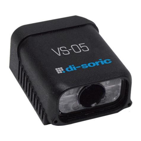
FIGURE 1–1. VS-06 Smart Camera, C-Mount and Standard Models

Chapter 1Introduction
1-2 VS-06 Smart Camera Guide
Product Summary
The VS-06 Smart Camera is a compact industrial smart camera that
provides powerful machine vision capabilities with a small form factor and
intuitive software interface. The VS-06 is designed for industrial
environments where IP65/67 enclosure and rugged M12 connectivity are
required.
Fully-integrated I/O and communications make the VS-06 easy to
incorporate in virtually any machine vision application. Patented liquid
lens autofocus and modular optical zoom enables the VS-06 to inspect
objects at distances from 33 mm to 2 m and beyond.
Pressing the AutoVision button at the back of the VS-06 enables real time
dynamic autofocus. When an object is centered in the field of view and
the AutoVision button is pressed, the camera automatically adjusts focal
distance and sets internal parameters to optimize image captures.
AutoVision software, designed for use with the VS-06, provides an
intuitive interface, step-by-step configuration, and a library of presets that
allow easy setup and deployment. For more complex vision applications,
the system can be upgraded from AutoVision to Visionscape.
Features and Benefits
• Standard and C-Mount models available
• SXGA (1280 x 960), WVGA (752 x 480), and WUXGA (2048 x 1088,
C-Mount model only) resolutions available
• World’s first vision system with liquid lens autofocus (standard models)
• Integrated lighting (standard models)
• Integrated Ethernet
• Flexible programming options for custom applications
• AutoVision button for automatic targeting, calibration, and triggering
• Simplified configuration with AutoVision software
• Fully scalable with Visionscape
• Applications can be ported to Visionscape PC-based machine vision

Applications
Introduction
1
VS-06 Smart Camera Guide 1-3
Applications
• Automotive assembly verification
• Part identification
• Label positioning
• Contents verification
• Electronics assembly verification and identification
• Semiconductor packaging and component inspection
• Auto ID (Data Matrix and other 2D symbologies, 1D, OCR)
Package Contents
Before you install VS AutoVision software and connect your VS-06 Smart
Camera, please take a moment to confirm that the following items are
available:
• VS-06 Smart Camera — Your package contains one of the available
models listed in Table 1–1
• di-soric Tools Drive — USB flash drive containing AutoVision software
• Required accessories such as a power supply or power cable

Chapter 1Introduction
1-4 VS-06 Smart Camera Guide
VS-06 Smart Camera Models
Table 1–1 lists and describes the VS-06 Smart Camera models.
TABLE 1–1. VS-06 Smart Camera Models
Part Number VS-06 Smart Camera Model
VS-06-BC3-00-ES VS-06, SXGA, AutoVision, C-Mount
VS-06E-BC3-00-ES VS-06, SXGA, AutoVision + Visionscape, C-Mount
VS-06-BM2-00-ES VS-06, WVGA, AutoVision, C-Mount
VS-06E-BM2-00-ES VS-06, WVGA, AutoVision + Visionscape, C-Mount
VS-06-BM2-15-ES VS-06, WVGA, Built-In Light, AutoVision, 15° Lens
VS-06-BM2-30-ES VS-06, WVGA, Built-In Light, AutoVision, 30° Lens
VS-06-BM2-45-ES VS-06, WVGA, Built-In Light, AutoVision, 45° Lens
VS-06E-BM2-15-ES VS-06, WVGA, Built-In Light, AutoVision + Visionscape, 15° Lens
VS-06E-BM2-30-ES VS-06, WVGA, Built-In Light, AutoVision + Visionscape, 30° Lens
VS-06E-BM2-45-ES VS-06, WVGA, Built-In Light, AutoVision + Visionscape, 45° Lens
VS-06-BC3-15-ES VS-06, SXGA, Built-In Light, AutoVision, 15° Lens
VS-06-BC3-30-ES VS-06, SXGA, Built-In Light, AutoVision, 30° Lens
VS-06-BC3-45-ES VS-06, SXGA, Built-In Light, AutoVision, 45° Lens
VS-06E-BC3-15-ES VS-06, SXGA, Built-In Light, AutoVision + Visionscape, 15° Lens
VS-06E-BC3-30-ES VS-06, SXGA, Built-In Light, AutoVision + Visionscape, 30° Lens
VS-06E-BC3-45-ES VS-06, SXGA, Built-In Light, AutoVision + Visionscape, 45° Lens
VS-06-BM4-00-ES VS-06, WVXGA, AutoVision, C-Mount
VS-06E-BM4-00-ES VS-06, WVXGA, AutoVision + Visionscape, C-Mount

Part Number Structure
Introduction
1
VS-06 Smart Camera Guide 1-5
Part Number Structure

Chapter 1Introduction
1-6 VS-06 Smart Camera Guide

VS-06 Smart Camera Guide 2-1
2
System Components
2
CHAPTER 2 System Components
This section contains information about system components as well as
information to help you connect the VS-06 Smart Camera. Specific
information describes connectors, adapters, cables, pinouts, and signals.
Note: There are no user-serviceable parts inside.
Hardware Components
Table 2-1 lists VS-06 Smart Camera hardware components.
TABLE 2–1. VS-06 Smart Camera Hardware Components
Part Number Description
Part Number VS-06 Smart Camera Model
VS-06-BC3-00-ES VS-06, SXGA, AutoVision, C-Mount
VS-06E-BC3-00-ES VS-06, SXGA, AutoVision + Visionscape, C-Mount
VS-06-BM2-00-ES VS-06, WVGA, AutoVision, C-Mount
VS-06E-BM2-00-ES VS-06, WVGA, AutoVision + Visionscape, C-Mount
VS-06-BM2-15-ES VS-06, WVGA, Built-In Light, AutoVision, 15° Lens
VS-06-BM2-30-ES VS-06, WVGA, Built-In Light, AutoVision, 30° Lens
VS-06-BM2-45-ES VS-06, WVGA, Built-In Light, AutoVision, 45° Lens
VS-06E-BM2-15-ES VS-06, WVGA, Built-In Light, AutoVision + Visionscape, 15° Lens
VS-06E-BM2-30-ES VS-06, WVGA, Built-In Light, AutoVision + Visionscape, 30° Lens

Chapter 2System Components
2-2 VS-06 Smart Camera Guide
VS-06E-BM2-45-ES VS-06, WVGA, Built-In Light, AutoVision + Visionscape, 45° Lens
VS-06-BC3-15-ES VS-06, SXGA, Built-In Light, AutoVision, 15° Lens
VS-06-BC3-30-ES VS-06, SXGA, Built-In Light, AutoVision, 30° Lens
VS-06-BC3-45-ES VS-06, SXGA, Built-In Light, AutoVision, 45° Lens
VS-06E-BC3-15-ES VS-06, SXGA, Built-In Light, AutoVision + Visionscape, 15° Lens
VS-06E-BC3-30-ES VS-06, SXGA, Built-In Light, AutoVision + Visionscape, 30° Lens
VS-06E-BC3-45-ES VS-06, SXGA, Built-In Light, AutoVision + Visionscape, 45° Lens
VS-06-BM4-00-ES VS-06, WVXGA, AutoVision, C-Mount
VS-06E-BM4-00-ES VS-06, WVXGA, AutoVision + Visionscape, C-Mount
Power Supplies
VSID-PS-24V-ES Power Supply, M12 12-pin Socket, 1.3 m
Communication Devices and Cables
VSID-IB-ES Interface Device
VKHM-Z-1/12/DB9-K Cordset, Host, Serial M12 12 pin Socket (Screw-on) to DB9 Socket, 1M
Accessories
VSID-BW-004 L-Bracket Kit
VSID-R90-002 Right Angle Mirror Kit
VSID-W-K-000 Window Replacement Kit
VSID-L-S-15 15° Lens Kit
VSID-L-S-30 30° Lens Kit
VSID-L-S-45 45° Lens Kit
VSID-W-G-850 Glass WIndow Kit with Infrared (IR) Filter
VSID-W-G-000 Glass Window Kit
VSID-LP-C-48 Lens Protection Housing, Standard Length (up to 48mm)
VSID-LP-C-72 Lens Protection Housing, Long (up to 72mm)
VSID-06-BE-3 Blue light LED-board for VS-06 (exect C-Mount)
VSID-06-BE-5 White light LED-board for VS-06 (exect C-Mount)
VS-UP-AV/VS Upgrade AutoVision to Visionscape
VS-UP-AV/OCV Upgrade AutoVision to Verification / OCV
VS-UP-AV/VS-OCV Upgrade AutoVision VisionScape + Verification / OCV
Note: Additional hardware components and cables are available in the di-soric Product portfolio.
Power Supplies
VSID-PS-24V-ES Power Supply, M12 12-pin Socket, 1.3 m
TABLE 2–1. VS-06 Smart Camera Hardware Components (Continued)
Part Number Description

Hardware Components
System Components
2
VS-06 Smart Camera Guide 2-3
Communication Devices and Cables
VKHM-Z-5/12-A Power I/O cable, 12 Pin, shielded, 5m
VKHM-Z-5/RJ45 Ethernet cable, flex-chain, 5m
VKSM-Z-5/12-A Power I/O cable, 12 Pin, shielded, flex-chain, 5m
Note: Additional hardware components are available in the di-soric Product Pricing Catalog.
TABLE 2–1. VS-06 Smart Camera Hardware Components (Continued)
Part Number Description

Chapter 2System Components
2-4 VS-06 Smart Camera Guide
Standard Front
Figure 2-1 shows the front of the VS-06 Smart Camera.
FIGURE 2–1. Front
Standard Base
Figure 2–2 shows the base of the VS-06 Smart Camera.
FIGURE 2–2. Base

Hardware Components
System Components
2
VS-06 Smart Camera Guide 2-5
Standard Side
Figure 2-3 shows the side of the VS-06 Smart Camera.
FIGURE 2–3. Side
Standard Back
Figure 2-4 shows the back of the Smart Camera.
FIGURE 2–4. Back

Chapter 2System Components
2-6 VS-06 Smart Camera Guide
C-Mount Front
Figure 2-5 shows the front of the C-Mount Smart Camera.
FIGURE 2–5. Front
C-Mount Base
Figure 2–6 shows the top of the C-Mount Smart Camera.
FIGURE 2–6. Top
Other manuals for VS-06
1
Table of contents
Other Di-soric Digital Camera manuals
