Di-soric VS-05 User manual

VS-05 Smart Camera Guide

Copyright ©2013
All rights reserved. The information contained herein is proprietary and is provided solely for the purpose of allow-
ing customers to operate and/or service di-soric manufactured equipment and is not to be released, reproduced,
or used for any other purpose without written permission of di-soric.
Throughout this manual, trademarked names might be used. Rather than place a trademark (™) symbol at every
occurrence of a trademarked name, we state herein that we are using the names only in an editorial fashion, and to
the benefit of the trademark owner, with no intention of infringement.
Disclaimer
The information and specifications described in this manual are subject to change without notice.
Latest Manual Version
For the latest version of this manual, see the Download Center on our web site at:
www.di-soric.com.
Technical Support
Warranty and Terms of Sale
For Standard Warranty information contact:
di-soric GmbH & Co. KG
Steinbeisstraße 6
DE-73660 Urbach
Fon: +49 (0) 71 81 / 98 79 - 0
Fax: +49 (0) 71 81 / 98 79 - 179
www.di-soric.com

VS-05 Smart Camera Guide iii
Contents
PREFACE Welcome! v
Purpose of This Manual v
Manual Conventions v
CHAPTER 1 Introduction 1-1
Product Summary 1-2
Features and Benefits 1-2
Applications 1-3
Package Contents 1-3
VS-05 Smart Camera Models 1-4
Part Number Structure 1-4
CHAPTER 2 System Components 2-1
Hardware Components 2-1
Important Label Information 2-4
Mounting and Wiring the VS-05 Smart Camera 2-5
Status Indicators 2-10
AutoVision Button 2-11
Trigger Debounce 2-12
CHAPTER 3 Optics and Lighting 3-1
Optics 3-2
Illumination 3-3

Contents
iv VS-05 Smart Camera Guide
APPENDIX A Connector Pinouts A-1
VS-05 Smart Camera Connectors A-2
APPENDIX B Cable Specifications B-1
61-000208-01 USB Type A to USB Type B Plug Cable B-2
61-000105-01 Host Cable, MS-Connect 210 to Host, Stripped to 9-Pin
Socket
B-3
VSID-K-25S/9K-2 Communication Cable, DB25 Plug to DB9 Socket B-6
VSID-PS-24V-ES Power Supply, 90-254 VAC, 24VDC, USA/Euro Plug B-8
APPENDIX C General Specifications C-1
Dimensions C-5
Field of View and Working Distance C-6
APPENDIX D Serial Commands D-1
APPENDIX E VS-05 Diagnostic Boot Mode D-1

V6-05 Smart Camera Guide 5
Preface
PREFACE Welcome!
Purpose of This Manual
This manual contains detailed information about the VS-05 Smart
Camera.
Manual Conventions
The following typographical conventions are used throughout this manual.
• Items emphasizing important information are bolded.
• Menu selections, menu items and entries in screen images are
indicated as: Run (triggered), Modify..., etc.

Preface
6Vs-05 Smart Camera Guide

VS-05 Smart Camera Guide
1-1
1
Introduction
1
CHAPTER 1 Introduction
FIGURE 1–1. VS-05 Smart Camera

Chapter 1Introduction
1-2 VS-05 Smart Camera Guide
Product Summary
The VS-05 Smart Camera is designed for reliable vision performance in
embedded identification and inspection applications. As the world’s
smallest fully-integrated vision system, the VS-05’s compact size and
wide angle optics provide the best performance available for machine
vision tasks at close range.
The VS-05 allows OEM design engineers to implement inspection, color
matching, symbol decoding, OCR, and more, in a single compact
solution. The camera’s small form factor allows flexible positioning in tight
spaces. The lightweight and durable magnesium alloy case weighs less
than 2 ounces.
Pressing the AutoVision button at the back of the VS-05 enables real time
dynamic autofocus. When an object is centered in the field of view and
the AutoVision button is pressed, the camera automatically adjusts focal
distance and sets internal parameters to optimize image captures.
di-soric AutoVision software, designed for use with the VS-05, provides
an intuitive interface, step-by-step configuration, and a library of presets
that allow easy setup and deployment. For more complex vision
applications,
the system can be upgraded from AutoVision to VisionScape.
Features and Benefits
• World’s smallest fully functional vision system
• USB connectivity
• OEM-ready for easy integration
• Integrated lighting and autofocus lens
• Flexible programming options for custom applications
• AutoVision button for automatic targeting, calibration, and triggering
• Simplified configuration with AutoVision software

Applications
Introduction
1
VS-05 Smart Camera Guide
1-3
Applications
• Part presence/absence
• Color detection and matching
• Medical device inspection
• Fiducial location
• Part location/orientation detection
• Packaging
• Robotics
• Auto ID (Data Matrix and other 2D symbologies, 1D, OCR)
Package Contents
Before you install AutoVision software and connect your VS-05 Smart
Camera, please take a moment to confirm that the following items are
available:
• VS-05 Smart Camera — Your package contains one of the available
models listed in Table 1–1.
• USB Type A to USB Type B Cable
• AutoVision Software Installation USB Drive

Chapter 1Introduction
1-4 VS-05 Smart Camera Guide
VS-05 Smart Camera Models
Table 1–1 lists and describes the VS-05 Smart Camera models, including
acquisition modes and resolutions.
TABLE 1–1. VS-05 Smart Camera Models
Part Number VS-05 Smart Camera Model
VS-05-BM3-2-US VS-05 Smart Camera, USB, SD, SXGA, Built-In Light, AutoVision
VS-05E-BM3-2-US VS-05 Smart Camera, USB, SD, SXGA, Built-In Light, AutoVision + VisionScape
VS-05-BM3-3-US VS-05 Smart Camera, USB, HD, SXGA, Built-In Light, AutoVision
VS-05E-BM3-3-US VS-05 Smart Camera, USB, HD, SXGA, Built-In Light, AutoVision + VisionScape
VS-05-BM2-2-US VS-05 Smart Camera, USB, SD, WVGA, Built-In Light, AutoVision
VS-05E-BM3-2-US VS-05 Smart Camera, USB, SD, WVGA, Built-In Light, AutoVision + VisionScape
VS-05-BM2-3-US VS-05 Smart Camera, USB, HD, WVGA, Built-In Light, AutoVision
VS-05E-BM3-3-US VS-05 Smart Camera, USB, HD, WVGA, Built-In Light, AutoVision + VisionScape

VS-05 Smart Camera Guide -1
System Components
1
CHAPTER System Components
This section contains information about system components as well as
information to help you connect the VS-05 Smart Camera. Specific
information describes connectors, adapters, cables, pinouts, and signals.
Note: There are no user-serviceable parts inside.
Hardware Components
Table 2-1 lists VS-05 Smart Camera hardware components.
TABLE –1 VS-05 Smart Camera Hardware Components
Part Number Description
Upgrade to VisionScape
VS-UP-AV/VS
Upgrade from AutoVision to verifikation AM/DPM+VisionScape
VS-UP-AV/VS-OCV
Upgrade from AutoVision to full VisionScape verifikation AM/DPM+OCV
Power Supply
VSID-PS-IB Power Supply, Interface Box, 90-254 VAC, 24VDC, USA/Euro Plug
Communication and I/O Devices and Cables
VSID-A-24/5V-S 24/5VAdapter
VSID-IB-S Interface Box, serial

Chapter 2System Components
-2 VS-05 Smart Camera Guide
Communication and I/O Devices and Cables
VSID-A-24/5V-S Adapter 24V / 5V
VSID-IB-S Interface Box
VSID-K-25S/9K-2 Communication Cable, DB25 Plug to DB9 Socket, 6’
Mounting Options
VSID-BW-003 Through-Hole Mount Bracket
VSID-BW-001 Side Mount Bracket
VSID-R90-001 Right-Angle Mirror Kit
VSID-DIF-001 Diffuser Accessory Kit
TABLE 1–1. VS-05 Smart Camera Hardware Components (Continued)
Part Number Description

Hardware Components
System Components
1
VS-05 Smart Camera Guide -3
Front
Figure 1–1 shows the front of the VS-05 Smart Camera.
FIGURE 1–1. Front
Base
Figure 2–2 shows the base of the VS-05 Smart Camera.
FIGURE 1–2. Base
Chapter 2System Components
-4 VS-05 Smart Camera Guide
Back
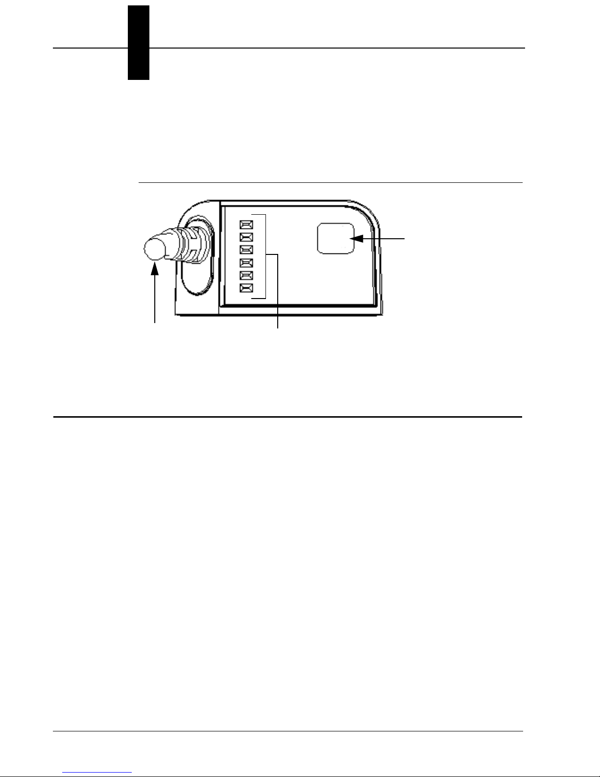
Figure 2-3 shows the back of the VS-05 Smart Camera.
FIGURE 1–3. Back
Important Label Information
Each VS-05 Smart Camera has its own label, which contains important
information about that camera.
• P/N – The di-soric part number of your VS-05 Smart Camera.
• S/N — The serial number of your VS-05 Smart Camera.
• MAC — The MAC address of your VS-05 Smart Camera.
• Type — The model type of your VS-05 Smart Camera.
USB / I/O cable
(attached)
AutoVision
Button
Status Indicators (TRIG, PASS,
FAIL, MODE, LINK/ACT, PWR)
Mounting and Wiring the VS-05 Smart Camera
System Components
1
VS-05 Smart Camera Guide -5
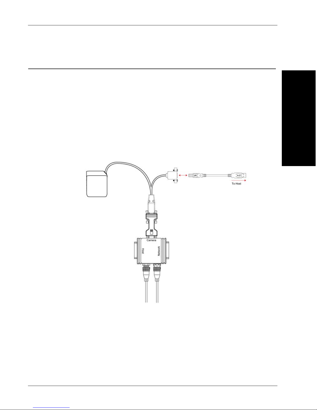
Mounting and Wiring the VS-05 Smart Camera
• Mount the camera (1) securely in its camera stand (not supplied).
• Make sure the camera (1) is mounted at the optimal distance of 2” to 6”.
• Mount the camera (1) as required by the application.
• Connect the USB side of the camera cable (2) to the USB host cable (3).
• Connect the VSID-A-24/5V-S (4) to the VSID-IB-S (5).
• Connect the D-sub side of the camera cable (2) to the VSID-A-24/5V-
S (4).
• Connect the trigger (6) to the VSID-IB-S (5).
• Connect the power supply (7) to the VSID-IB-S (5).
• Plug in the power supply (7).
7
1
2
3
6
4
5

Chapter 2System Components
-6 VS-05 Smart Camera Guide
Direct Input / Output Diagrams

Mounting and Wiring the VS-05 Smart Camera
System Components
1
VS-05 Smart Camera Guide -7
Isolated Trigger Input with VSID-A-24/5V-S
Chapter 2System Components
-8 VS-05 Smart Camera Guide
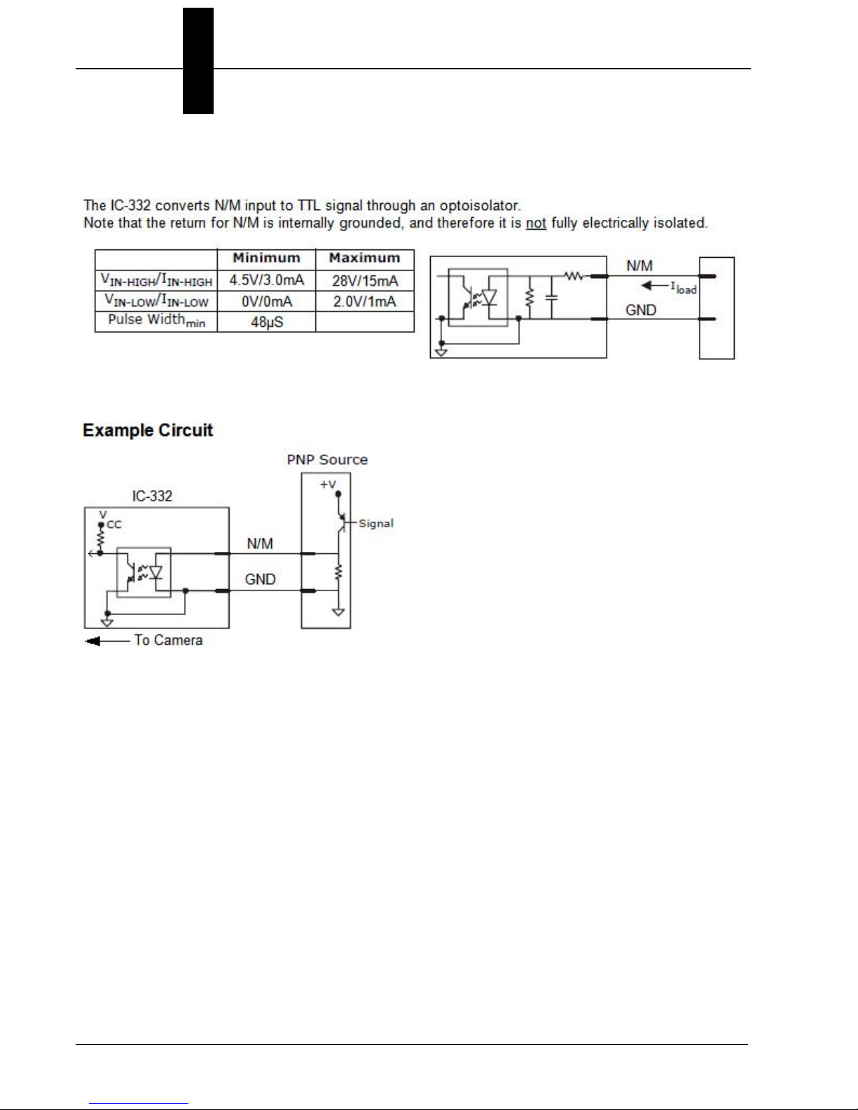
New Master Input with VSID-A-24/5V-S

Mounting and Wiring the VS-05 Smart Camera
System Components
1
VS-05 Smart Camera Guide -9
Power Requirements
Refer to Table 2-3 when determining the power supply requirements for
your camera.
TABLE 1–3. Camera Power Requirements
Component 5VDC
VS-05 Smart Camera WVGA 5VDC +/– 5%, 200 mV p-p max.
ripple, 400 mA @ 5VDC (typ.), 4.0
watts (max.)
VS-05 Smart Camera SXGA 5VDC +/– 5%, 200 mV p-p max.
ripple, 465 mA @ 5VDC (typ.), 4.5
watts (max.)

Chapter 2System Components
-10 VS-05 Smart Camera Guide
Status Indicators
The back of the VS-05 Smart Camera has multiple LEDs that indicate
different trigger, inspection, camera, communication, and power states.
Additional User Feedback
• Green Flash – A green flash from the front of the unit indicates a Good Read.
• Blue Targeting Pattern – The blue targeting pattern from the front of the
unit allows the user to center an object in the camera’s field of view.
• Beeper – The beeper is an audible verification that either a Pass or a
Fail has occurred.
TRIG
On Steady Continuous Trigger
Off Waiting for Trigger Event
On Flashing Trigger Event
PASS/FAIL On Active State
Off Inactive State
MODE On Steady Unit Ready
Off Unit Not Ready
LINK/ACT
On Steady Link Established
Off No Link/Activity
On Flashing Link Established and Activity on Link
PWR On Power On
Off No Power Applied to Unit
Trigger Status
Inspection Status
Camera Status
Communication Status
Power Status
Other manuals for VS-05
1
Table of contents
Other Di-soric Digital Camera manuals


