Di-soric SB-RGB User manual
IO-LINK SIGNAL LIGHTING &
SIGNAL LIGHTS
SB-RGB, SBT-RGB & SBP-RGB
OPERATING INSTRUCTIONS
600017-0000EN · Rev 1 · 2023/01

IOL SIGNAL LIGHTING & SIGNAL LIGHTS IOL SIGNAL LIGHTING & SIGNAL LIGHTS2
600017-0000EN · Rev 1 · 2023/01
TABLE OF CONTENTS
1 PRELIMINARY NOTE 3
2 OVERVIEW 4
3 GENERAL DESCRIPTION 5
4 NORMAL OPERATION AND APPLICATION AREAS 5
4.1 Reliably signaling various statuses .................................................................................................................................. 5
4.2 Signal lighting: suitable for a variety of uses .................................................................................................................... 5
4.3 Ambient conditions [IP protection classes]...................................................................................................................... 5
5 OPERATING MODES 6
5.1 External Trigger mode..................................................................................................................................................... 6
5.2 Operation via IO-Link [Segment mode, Level mode, Demo mode] ................................................................................... 6
5.2.1 Communication via IO-Link.................................................................................................................................... 6
5.2.2 Segment mode ..................................................................................................................................................... 6
5.2.3 Level mode ........................................................................................................................................................... 6
5.2.4 Demo mode .......................................................................................................................................................... 6
6 COMMISSIONING 7
6.1 Operation without IO-Link in External Trigger mode......................................................................................................... 7
6.2 Operation with di-soric IO-Link master............................................................................................................................ 7
6.3 Operation with other PLC online tools: e.g. Siemens master............................................................................................ 8
7 PARAMETERIZATION AND CONFIGURATION 9
7.1 Basic functions .............................................................................................................................................................. 9
7.1.1 Color configuration and designation....................................................................................................................... 9
7.1.2 Standard commands........................................................................................................................................... 10
8 OPERATING MODES 10
8.1 External Trigger mode [standard mode]......................................................................................................................... 11
8.1.1 Parameterization [parameter data]........................................................................................................................ 11
8.1.2 Application example ........................................................................................................................................... 12
8.2 Segment mode ............................................................................................................................................................ 13
8.2.1 Parameterization [parameter data]........................................................................................................................ 13
8.2.2 Process data and application example................................................................................................................. 14
8.3 Level mode .................................................................................................................................................................. 15
8.3.1 Parameterization [parameter data]........................................................................................................................ 15
8.3.2 Process data and application example................................................................................................................. 16
9 TROUBLESHOOTING 17
9.1 Error display................................................................................................................................................................. 17

IOL SIGNAL LIGHTING & SIGNAL LIGHTS2 3
600017-0000EN · Rev 1 · 2023/01
SBT-RGB
SBP-RGB
SB-RGB
1 PRELIMINARY NOTE
Foreword | Purpose
This quick guide helps you with the initial commissioning process for di-soric SBx-RGB signal lighting and with using the
USB IO-Link master to configure parameters. The quick guide is a supplementary document for the existing product
documentation.
For more information, see: http://www.di-soric.com

IOL SIGNAL LIGHTING & SIGNAL LIGHTS IOL SIGNAL LIGHTING & SIGNAL LIGHTS4
600017-0000EN · Rev 1 · 2023/01
2 OVERVIEW
Product overview: IOL signal lighting & signal lights
SBP-RGB 1-segment IOL
signal lights SBP-RGB-R50D-B5
Segments 1
Operating mode Trigger mode, Segment mode, Demo mode
Color Red, green, yellow, blue, white, orange, pink, user-defined (IO-Link), RGB color spectrum
Brightness / intensity 10 to100%, can be freely customized via IO-Link
Frequency / mode Constant light, flashing light, blinking light
SB-RGB multi-segment IOL
signal lighting SB-RGB-126-K-B5 SB-RGB-251-K-B5 SB-RGB-481-K-B5 SB-RGB-701-K-B5 SB-RGB-911-K-B5
Segments 2 3 6 9 12
Operating mode Trigger mode, Segment mode, Level mode, Demo mode
Color Red, green, yellow, blue, white, orange, pink, user-defined (IO-Link), RGB color spectrum
Brightness / intensity 10to 100%, can be freely customized via IO-Link
Frequency / mode Constant light, flashing light, blinking light
SBT-RGB multi-segment IOL
signal columns with/without
buzzer
SBT-RGB-R50-
3S-B5
SBT-RGB-R50-
3B-B5
SBT-RGB-R50-
4S-B5
SBT-RGB-R50-
4B-B5
SBT-RGB-R50-
5S-B5
SBT-RGB-R50-
5B-B5
Segments 3 3 4 4 5 5
Buzzer Without With Without With Without With
Operating mode Trigger mode, Segment mode, Level mode, Demo mode
Color Red, green, yellow, blue, white, orange, pink, user-defined (IO-Link), RGB color spectrum
Brightness / intensity 10to 100%, can be freely customized via IO-Link
Frequency / mode Constant light, flashing light, blinking light

IOL SIGNAL LIGHTING & SIGNAL LIGHTS4 5
600017-0000EN · Rev 1 · 2023/01
3 GENERAL DESCRIPTION
Signal lighting is indispensable for safety in the industry or in the public sphere because it reliably provides a visual warning to
and protects not only the workers, but also passersby. Particularly in the industry at indoor and outdoor facilities, for example,
signal lighting supports workplace safety by indicating various operating states of machines and systems. Signal columns, for
example, can of course be used in other situations, too. The optical signal transducers help you monitor machines and complex
manufacturing processes, identify emergency or hazardous situations so that action can be taken in good time if the safety of
the environment, people or products is in jeopardy. di-soric signal lights and signal lighting have the advantage that they can be
configured to suit your individual needs via IO-Link. The signal lights can be integrated into any machine and system with practical
accessories for signal lighting.
4 NORMAL OPERATION AND APPLICATION AREAS
The di-soric signal lighting and signal lights are operated with a service voltage of 18 to 30 V.
On machines and systems with IO-Link, the device is connected to a class A port of the IO-Link master with a 3 to 5-pin M12
connecting line.
On machines and systems without IO-Link, the device is connected to a 5-pin cable, with the presets being activated via
the 3 digital inputs.
Even from a great distance, the signal lighting indicates the status of machines or machine segments in a clearly visible way
with vibrant colors.
4.1 RELIABLY SIGNALING VARIOUS STATUSES
By using professional signaling, you ensure more safety in your applications and considerably reduce response and waiting times.
Due to the dierent signaling stages, employees can promptly react to faults and more quickly fix any existing problems.
Attention is additionally drawn by the loud buzzer integrated into the cover of the SBT signal towers.
4.2 SIGNAL LIGHTING: SUITABLE FOR A VARIETY OF USES
It is impossible to imagine mechanical engineering and plant construction without signal columns But signal lighting is also found
in many other areas, such as intralogistics and building services engineering.
4.3 AMBIENT CONDITIONS [IP PROTECTION CLASSES]
The di-soric SBx-RGB lighting is typically suited for industrial applications; depending on the variants, they have the following IP
protection types: IP20, IP 65 and IP 67.

IOL SIGNAL LIGHTING & SIGNAL LIGHTS IOL SIGNAL LIGHTING & SIGNAL LIGHTS6
600017-0000EN · Rev 1 · 2023/01
5 OPERATING MODES
The di-soric LED signal lighting (SBx-RGB) can be operated via IO-Link as well as via the integrated digital inputs. In total,
4 operating modes are available: External Trigger mode, Segment mode, Level mode, Demo mode:
It is important to mention that the SBP-RGB is only operated with 3 operating modes, namely, External Trigger mode, Segment
mode and Demo mode. Level mode is not possible for the SBP-RGB series because the SBP-RGB has only one segment.
5.1 EXTERNAL TRIGGER MODE
In External Trigger mode (factory setting), 8 predefined color and lighting configurations can be activated through the 3 digital
trigger inputs, even without IO-Link.
5.2 OPERATION VIA IO-LINK [SEGMENT MODE, LEVEL MODE, DEMO MODE]
5.2.1 COMMUNICATION VIA IO-LINK
IO-Link is a globally standardized I/O technology (IEC61131-9) for communication
between control system and sensor/actuator below the fieldbus level.
The well-known connection technology is used with unshielded M12 cables. Here,
the 3-wire connection of a digital switching signal is enhanced by the bidirectional
communication.
5.2.2 SEGMENT MODE
In Segment mode, individual segments can be activated via IO-Link process data,
which enables countless color configurations. IO-Link can be used on the fly to set
the colors of each segment, the intensity from 10 to 100% and blinking or flashing
behavior.
5.2.3 LEVEL MODE
Level mode is for displaying fill levels and process progress. In Level mode, the signal
light requires an input value from the control system between 0 and 100 percent.
Furthermore, there is the option of using IO-Link process data to define a background
color (inactive segment) and a color of the active segment.
5.2.4 DEMO MODE
In Demo mode, the device demonstrates the dierent operating functions: dierent
colors, Level mode, Segment mode, blinking, flashing and, if present, an acoustic
signal.
Fieldbus
PLC
Industrial
Ethernet
IOL MASTER
SIO
Possible system architecture

IOL SIGNAL LIGHTING & SIGNAL LIGHTS6 7
600017-0000EN · Rev 1 · 2023/01
6 COMMISSIONING
For initial commissioning of our signal lighting, you need either a control system with 3 free digital outputs and a 5-wire
connecting cable with M12 socket or, if you want to connect the lighting to IO-Link, then you need a compatible IO-Link
master and a 5-wire connecting cable with M12 socket.
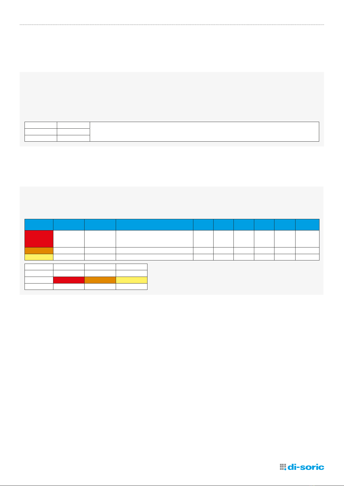
6.1 OPERATION WITHOUT IO-LINK IN EXTERNAL TRIGGER MODE
The lighting and/or products arrive from the factory in External Trigger mode. The 3 digital inputs can be used to activate the
predefined presets for the lights. The statuses that are displayed when the respective preset is activated depend on the product
and are described in the data sheet for the respective product. As an example, here is an excerpt from a data sheet from the
SBP-RGB series:
Operating mode: External trigger
BN 1
2WH
BU 3
5GY
BK 4
Trigger 1
Trigger 2
Trigger 3
TRIG 1 TRIG 2 TRIG 3 Pre-Set Factory setting
0001O
1002Red
0103Green
1104Yellow
0015Blue
1016Red blinking
0117Green blinking
1118Yellow blinking
All Trigger Inputs have a delay ~50 ms.
Pre-sets can be defined via IO-Link.
Operating mode: External Trigger
Trig 1 Trig 2 Trig 3 Preset Factory setting
0 0 0 1 O
1 0 0 2 Red
0 1 0 3 Green
1 1 0 4 Yellow
0 0 1 5 Blue
1 0 1 6 Red blinking
0 1 1 7 Green blinking
1 1 1 8 Yellow blinking
All trigger inputs have a delay ~50 ms. Presets can be defined via IO-Link.
6.2 OPERATION WITH DI-SORIC IO-LINK MASTER
Our signal lighting and signal lights from the SBx-RGB series can be configured directly with a computer running Windows 7 or
later, in combination with the di-soric USB IO-LINK MASTER and the associated “IOL Device Tool” software.
IOL MASTER:
Operation on PC via USB
The IO-Link devices are described by means of XML device descriptions, so they can be quickly
and easily observed and configured. The tool is designed for presetting, testing and
demonstrating IO-Link devices. The tool is not intended for ongoing operation in production
systems.
In addition to the computer and IO-Link master with software, you also need the IODDs of the
respective signal lights. You will find these in our product selector under the respective product on
the Downloads tab.
The IODD is a ZIP file in which the actual IODD is compressed with the associated graphics files.
After the files are imported into your engineering tool, the lighting functions can be visualized and
programmed.
You can also find the IODDs in the IODDfinder portal of the IO-Link Consortium: ioddfinder.io-link.com
For details about the functions and additional information for integrating IO-Link devices with the di-soric USB IO-Link master,
please see the user manual for the IOL master: www.di-soric.com/210075

IOL SIGNAL LIGHTING & SIGNAL LIGHTS IOL SIGNAL LIGHTING & SIGNAL LIGHTS8
600017-0000EN · Rev 1 · 2023/01
6.3 OPERATION WITH OTHER PLC ONLINE TOOLS: E.G. SIEMENS MASTER
Figure 1 – External Trigger mode (factory configuration)
Figure 2 – Segment mode (bytes for the process data are assigned)
S7-PCT with IODD of a device and the contained device information
Important note: Before operation with IO-Link, the IO-Link
devices should be switched from External Trigger mode
(factory configuration) to Segment mode or Level mode.
(see Figures 1 and 2)
It is entirely possible to use other engineering tools
for planning and parameterization of IO-Link devices:
Example: Siemens master with Port Configuration Tool
(“PCT”).
The Port Configuration Tool (“PCT”) is PC-based software
for parameterization of Siemens IO-Link master modules
and IO-Link devices from any manufacturer. The IO-
Link devices are integrated through the standardized
“IODD” device description, which can be obtained from
the respective device manufacturer or at the IODDfinder
portal (ioddfinder.io-link.com).
With the Siemens IO-Link master, it is necessary to make
sure that the latest IODD file revised for this is used. This
can be identified by the time code (Release Date: 2022-
04-25). For example, for the SB-RGB-126-K-B5 signal
lighting it looks like this: di-soric-SB-RGB-126-K-B5-
20220425-IODD1.1-de.html.
If a previous version of the IODD is installed, then this
must first be completely removed from the Siemens
master. Then the PCT tool must be restarted; after that,
the new version can be used.

IOL SIGNAL LIGHTING & SIGNAL LIGHTS8 9
600017-0000EN · Rev 1 · 2023/01
7 PARAMETERIZATION AND CONFIGURATION
7.1 BASIC FUNCTIONS
Among other things, di-soric signal lighting has 3 basic functions: color configuration, locator function and reset to factory
settings. The colors are configured to indexes [650to 657] by the “Color content” variable and to indexes [620 to 627] by the
“Designation” variable.
The “Locator function” at index [126=Locator Start, 127=Locator Stop] and the Reset to the factory setting
with the values [200 to207] are at subindexes 16 and are located under the “Standard command” standard variable
index=2 id=V_SystemCommand.
The Locator function is at 126 for Locator Start and 127 for Locator Stop; it enables the integrated product to be quickly found
in the system.
The factory settings are restored through the allowed value 130 as the subindex.
7.1.1 COLOR CONFIGURATION AND DESIGNATION
In the color configuration it is possible to configure 8 dierent colors; the “Color content” variables lie at the
indexes=650 to 657 and have the id=V_ColorRGB0 to V_ColorRGB7. The colors red, green and blue lie at the
subindexes=1,2,3 and are indicated with values 0 to 100.
The “Designation” variables lie at the indexes=620 to 627 and have the id=V_ColorDesignation0 to
V_Color Designation7. The color designations can be freely changed and have a data type of 32-octet string UTF-8.
Configuration color 000
“Color content” variable index=600 id=V_ColorRGB0
description: Color content
data type: 24-bit record
access rights: rw
dynamic
subindex bit oset data type allowed values default value acc. restr. mod. other var. excl. from DS name description
1 16 8-bit Ulnteger 0 to 100 0 Red Red part
2 8 8-bit Ulnteger 0 to 100 0 Green Green part
3 0 8-bit Ulnteger 0 to 100 0 Blue Blue part
octet 0 1 2
bit oset 23-16 15-8 7-0
subindex 1 2 3
element bit 7-0 7-0 7-0
Trigger preset 1 (TRIG1=0, TRIG2=0, TRIG3=0)
“Designation” variable index=620 id=V_ColorDesignation0
description: Designation can be freely selected
data type: 32-octet string UTF-8
default value: “O (factory setting)”
access rights: rw
dynamic
octet 0 1 2 3 4 5 6 7
bit oset 255–248 247-240 239-232 231-224 223-216 215-208 207-200 199-192
octet 8 9 10 11 12 13 14 15
bit oset 191-184 183-176 175-168 167-160 159-152 151-144 143-136 135 128
octet 16 17 18 19 20 21 22 23
bit oset 127-120 119-112 11-104 103-96 95-88 87-80 79-72 71-64
octet 24 25 26 27 28 29 30 31
bit oset 63-56 55-48 47-40 39-32 31-24 23-16 15-8 7-0
For example, for ColorDesignation0 the index lies at the value 620. At index=620 the color is o or dark by default (factory
setting).

IOL SIGNAL LIGHTING & SIGNAL LIGHTS IOL SIGNAL LIGHTING & SIGNAL LIGHTS10
600017-0000EN · Rev 1 · 2023/01
7.1.2 STANDARD COMMANDS
For the Locator function and factory setting, the “Standard command” standard variable lies at index=2 with the
id=V_SystemCommand. Restore the allowed values 126 for Locator Start and 127 for Locator Stop, as well as 130
for restoring to factory settings. For Reset to factory settings for ColorDesignation0to7, the allowed values lie between
[200 to 207].
“Standard command” standard variable index=2 id=V_SystemCommand
data type: 32-octet string UTF-8
allowed value: 126=Locator start, 127=Locator Stop, 130=Restore factory settings, 161=Function test, 162= Function test stop, 200=Reset to
factory settings, 201=Reset to factory settings, 202=Reset to factory settings, 203=Reset to factory settings,
204=Reset to factory settings, 205=Reset to factory settings, 206=Reset to factory settings, 207=Reset to factory settings,
240=IO-Link 1.1 system test command 240, Event 8DFF appears, 243=IO-Link 1.1 system test command 243, Event 8DFF appears
access rights: wo
modifies other variables
octet 0
bit oset 7-0
element bit 7-0
The Locator function enables the integrated product to be quickly found in the system.
The factory settings are restored through the allowed value 130 as the subindex.
8 OPERATING MODES
The signal lighting of the SB- and SBT-RGB series have four operating modes, which can be set by means of the “device control”
parameter:
• External Trigger mode (factory configuration)
• Segment mode (PD)
• Level mode (PD) [not available for the SBP lighting series]
• Demo mode
The operating modes can only be selected individually and cannot be combined. The operating mode is set by means of the
“device control” parameter.
“Device control” variable index=602 id=V_DeviceControl
description: Device control
data type: 8-bit Ulnteger
allowed value: 1=External Trigger mode, 2=Segment mode (PD), 3=Level mode (PD), 4=Demo mode
default value: 1
access rights: rw
octet 0
bit oset 7-0
element bit 7-0
The device control has index=602, the allowed values are 1=External Trigger mode, 2=Segment mode (PD),
3=Level mode (PD), and 4=Demo mode. The default value or standard value is typically 1 (external trigger).

IOL SIGNAL LIGHTING & SIGNAL LIGHTS10 11
600017-0000EN · Rev 1 · 2023/01
8.1 EXTERNAL TRIGGER MODE [STANDARD MODE]
The signal lighting of the SB-, SBP- and SBT-RGB series is delivered in Trigger mode. (factory configuration). This is the standard
operating mode at delivery. In this operating mode, each color of each segment is represented as a separate switching signal.
Important note: Complete integration into IO-Link is possible only with the new Gen. 2 devices possible, and these are stipulated
in this manual.
The delivery of Generation 2 lighting in Trigger mode enables backward compatibility with the devices of Generation 1.
Furthermore, Generation 1 devices dier from Generation 2 devices in terms of voltage range (Gen. 1: 24 V DC +-5%,
Gen. 2: 18 to30 V DC).
Preset color for each segment simulation
“Preset selection” variable index=604 id=V_TriggerSimulation
description: Simulation of all eight selectable presets in External Trigger mode in parallel with an IO-Link connection
data type: 8-bit Ulnteger
allowed value: 0=0 (simulation o), 1=preset 1, 2=preset 2, 3=preset 3, 4=preset 4, 5=preset 5, 6=preset 6, 7=preset 7, 8=preset 8
default value: 0
access rights: rw
excluded from data storage
octet 0
bit oset 7-0
element bit 7-0
For simulation of all eight selectable presets in Trigger mode, the index has the value 604 and the allowed base values for the
presets are [ 0- 8 ]: 0=(simulation o), 1=preset 1, 2=preset 2, 3=preset 3, 4=preset 4, 5=preset 5, 6=preset 6, 7=preset 7,
8=preset 8.
The default value or base value is typically 0.
8.1.1 PARAMETERIZATION [PARAMETER DATA]
Trigger mode means that customers can use digital inputs to switch predefined colors directly. Due to the 3 trigger inputs of the
lighting, the 8 predefined trigger presets can be selected.
For a trigger preset selection [preset 0to7], the following light functions (light color, intensity and mode) and buzzer function are
preset at the factory for each segment [1to 12] (depending on the variant). However, there is the option of simply using IO-Link to
freely and individually parameterize the trigger presets.
Recommended procedure for commissioning:
1.Configure colors
2.Configure presets
3.Simulate presets
IOL SIGNAL LIGHTING & SIGNAL LIGHTS IOL SIGNAL LIGHTING & SIGNAL LIGHTS12
600017-0000EN · Rev 1 · 2023/01
Buzzer function
For the variants that have a buzzer, a buzzer can also be configured in addition to the color configurations. Here, you can decide
whether the buzzer should emit a continuous tone or a slow or fast intermittent tone.
“Buzzer” variable index=700 id=V_SegmentPre-Set1_Buzzer
description: slow intermittent (1 Hz) / fast intermittent (2.5 Hz)
data type: 8-bit Ulnteger
allowed value: 0=o, 1=on (continuous), 2=slow intermittent, 3=fast intermittent
default value: 0
access rights: rw
octet 0
bit oset 7-0
element bit 7-0
Preset for each segment
In the preset segment configuration, the previously configured colors can be assigned to the individual presets or segments.
In addition, you can configure the light intensity as well as have the active segment be lit continuously, blink or flash.
“Seg 1” variable index=701 id=V_SegmentPre-Set1_1
description: Segment preset
data type: 24-bit record
access rights: rw
subindex bit oset data type allowed values default
value acc. restr. mod. other
var.
excl. from
DS name description
1 16 8-bit Ulnteger
0=color 001, 2=color 010, 3=color 011,
4=color 100, 5=color 101, 6=color 110,
7=color 111
0 Color Color
2 8 8-bit Ulnteger 0 to 100 100 Intensity Intensity
3 0 8-bit Ulnteger 0=static, 1=blinking, 2=flashing 0 Color Mode
octet 0 1 2
bit oset 23-16 15-8 7-0
subindex 1 2 3
element bit 7-0 7-0 7-0
8.1.2 APPLICATION EXAMPLE
To activate the color red in Trigger mode, the following pin assignment is connected:
Pin 2 (TRIG 1)=VDD, High level > 8.0 V
Pin 5 (TRIG 2)=GND, Low level < 5.0 V
Pin 4 (TRIG 3)=GND, Low level < 5.0 V
For the color green, the following pin assignment is required:
Pin 2 (TRIG 1)=GND, Low level < 5.0 V
Pin 5 (TRIG 2)=VDD, High level > 8.0 V
Pin 4 (TRIG 3)=GND, Low level < 5.0 V

IOL SIGNAL LIGHTING & SIGNAL LIGHTS12 13
600017-0000EN · Rev 1 · 2023/01
8.2 SEGMENT MODE
If the signal lighting or signal lights are completely integrated into the IO-Link communication, then it is advisable to operate the
product in Segment mode.
In Segment mode, individual segments can be activated via IO-Link process data, which enables countless color configurations.
IO-Link can be used on the fly to assign the previously configured colors and static, blinking or flashing lighting behavior to the
segments.
8.2.1 PARAMETERIZATION [PARAMETER DATA]
Depending on the selected number of segments, the various color combinations can be displayed. The intensity [10 to100] and
Dynamic mode [blinking or flashing] can also be set up freely.
The “Number of segments selection 1=1” setting applies the selected color to all the lighting. Important note: The index 610 is
not available for the SBP-RGB lighting.
Number of segments selection
“Number of segments selection” variable index=610 id=V_SelectionSegmentNumber
description: Selection of the number of segments in Segment mode (PD)
data type: 8-bit Ulnteger
allowed value: 1=1, 5=5
default value: 5
access rights: rw
Dynamic mode for each segment
In Segment mode, for example, for segment 1 the result is index=681 and for the intensity the result is subindex=1 and
the values are [10to100]. The factory setting is usually 100.
For Dynamic mode, the subindex=2 and the possible values are 1=blinking and 2=flashing. For the factory setting,
the value=1 is usually set.
“Seg 1” variable index=681 id=V_SegmentModus1
description: Segment
data type: 16-bit record
access rights: rw
subindex bit oset data type allowed values default
value acc. restr. mod. other
var.
excl. from
DS name description
1 8 8-bit Ulnteger 10 to 100 100 Intensity Intensity
2 0 8-bit Ulnteger 1=blinking, 2=flashing 1 Dynamic
mode
Dynamic
mode
octet 0 1
bit oset 15-8 7-0
subindex 1 2
element bit 7-0 7-0

IOL SIGNAL LIGHTING & SIGNAL LIGHTS IOL SIGNAL LIGHTING & SIGNAL LIGHTS14
600017-0000EN · Rev 1 · 2023/01
8.2.2 PROCESS DATA AND APPLICATION EXAMPLE
The process data of the devices is transmitted cyclically in a data telegram; the device defines the process data size. For each
device it is possible to have process data from 0 to 32 bytes (for both the input and output). In Segment mode, the process data
can be used to assign the 8 preconfigured colors to the individual segments or activate them. Furthermore, the (static or dynamic)
lighting mode can be selected for each segment. In addition, if products have a buzzer, this can be activated.
The ProcessDataOut “PD for Segment mode” is under the id=PDOUT_Segment at V_DeviceControl == 2. For example, the color
setting for Seg 3 is at subindex 6 and the buzzer is at subindex 7.
ProcessData id=PD_Segment (condition V_DeviceControl ==2)
ProcessDataOut “PD for Segment mode” id=PDOUT_Segment
bit length: 64
data type: 64-bit record (subindex access not supported)
subindex bit oset data type allowed values default
value acc. restr. mod.
other var.
excl. from
DS name description
1 63 Boolean false=static, true=dynamic Seg 1 mode
2 60 3-bit Ulnteger
0=color 000, 1=color 001, 2=color 010,
3=color 011, 4=color 100, 5=color 101,
6=color 110, 7=color 111
Seg 1 color
3 59 Boolean false=static, true=dynamic Seg 2 mode
4 56 3-bit Ulnteger
0=color 000, 1=color 001, 2=color 010,
3=color 011, 4=color 100, 5=color 101,
6=color 110, 7=color 111
Seg 2 color
5 55 Boolean false=static, true=dynamic Seg 3 mode
6 52 3-bit Ulnteger
0=color 000, 1=color 001, 2=color 010,
3=color 011, 4=color 100, 5=color 101,
6=color 110, 7=color 111
Seg 3 color
7 51 Boolean false=static, true=dynamic Seg 4 mode
8 48 3-bit Ulnteger
0=color 000, 1=color 001, 2=color 010,
3=color 011, 4=color 100, 5=color 101,
6=color 110, 7=color 111
Seg 4 color
9 47 Boolean false=static, true=dynamic Seg 5 mode
10 44 3-bit Ulnteger
0=color 000, 1=color 001, 2=color 010,
3=color 011, 4=color 100, 5=color 101,
6=color 110, 7=color 111
Seg 5 color
11 0 2-bit Ulnteger 0=o, 1=on (continuous), 2=slow intermittent,
3=fast intermittent Buzzer
In Segment mode, the number of segments [1 to12] of lighting (depending on variant) can be easily displayed and the
preconfigured colors [000to 111] selected for each segment can be optically visualized.
A variety of information can be clearly and optically displayed with the segments. The Segment mode setting causes the lighting
to accept only the commands for color changes, activation via the I/O-Link connection.
In Segment mode, the signal lighting can be used to display process progress. Thus the machine operator can immediately
determine the current status of manufacturing processes and act accordingly in case of error messages.

IOL SIGNAL LIGHTING & SIGNAL LIGHTS14 15
600017-0000EN · Rev 1 · 2023/01
8.3 LEVEL MODE
In Level mode, it is possible to use IO-Link process data to define a background color [inactive segment], which can be used,
for example, as a corporate identity color. In addition, the fill levels and machine status can be displayed with the active segments
[foreground color] with a predefined color selection.
8.3.1 PARAMETERIZATION [PARAMETER DATA]
Important note: Level mode is not available for SBP-RGB lighting because it has only one segment.
Segment behavior
“Mode” variable index=616 id=V_LevelMode
description: Mode
data type: 8-bit Ulnteger
allowed value: 0=segments increasing, 1=segment migrating
default value: 0
access rights: rw
octet 0
bit oset 7-0
element bit 7-0
For example, for Level mode the index=616 and the allowed values are 0=segments increasing, 1=segment migrating.
Level display direction
With the signal lighting Level mode, the display direction [Bottom>Top or Top>Bottom] can also be selected and optically
displayed.
“Display direction” variable index=615 id=V_LevelDisplayDirection
description: Display direction
data type: 8-bit Ulnteger
allowed value: 0=Bottom > Top, 1=Top > Bottom
default value: 0
access rights: rw
octet 0
bit oset 7-0
element bit 7-0
Dynamic mode for each segment
Furthermore, it is possible to define a foreground color with the index=617 [active segment level] and a background color
with the index 618 [inactive segment level]. For example, the background color can be set as a corporate identity color.
“Active segment dynamic mode” variable index=617 id=V_LevelActiveSegment
description: Active segment dynamic mode (foreground color)
data type: 8-bit Ulnteger
allowed value: 1=blinking, 2=flashing
default value: 1
access rights: rw
octet 0
bit oset 7-0
element bit 7-0

IOL SIGNAL LIGHTING & SIGNAL LIGHTS IOL SIGNAL LIGHTING & SIGNAL LIGHTS16
600017-0000EN · Rev 1 · 2023/01
“Inactive segment dynamic mode” variable index=618 id=V_LevelInactiveSegment
description: Inactive segment dynamic mode (background color)
data type: 8-bit Ulnteger
allowed value: 1=blinking, 2=flashing
default value: 1
access rights: rw
octet 0
bit oset 7-0
element bit 7-0
8.3.2 PROCESS DATA AND APPLICATION EXAMPLE
Process data (e.g. analog values) are transmitted cyclically. In Level mode, the process data transmits the analog value [0to100]
as an input, for example, so that fill levels and process progress can be displayed. The 8 preconfigured colors can be freely set
for the active segments as well as for the inactive segments. Furthermore, the (static or dynamic) lighting mode can be selected.
In addition, the buzzer can be activated. The buzzer's tone mode [slow or fast intermittent] can also be freely selected.
ProcessData id=PD_Level (condition V_DeviceControl ==3)
ProcessDataOut “PD for Level mode” id=PDOUT_Level
bit length: 64
data type: 64-bit record (subindex access not supported)
subindex bit oset data type allowed values default
value acc. restr. mod.
other var.
excl. from
DS name description
1 56 8-bit Ulnteger 0 to 100 Analog value
2 51 Boolean false=static, true=dynamic
Active
segments
mode
3 48 3-bit Ulnteger
0=color 000, 1=color 001, 2=color 010,
3=color 011, 4=color 100, 5=color 101,
6=color 110, 7=color 111
Active
segments
color
4 40 7-bit Ulnteger 10 to 100
Active
segments
intensity
5 35 Boolean false=static, true=dynamic
Inactive
segments
mode
6 32 3-bit Ulnteger
0=color 000, 1=color 001, 2=color 010,
3=color 011, 4=color 100, 5=color 101,
6=color 110, 7=color 111
Inactive
segments
color
7 24 7-bit Ulnteger 10 to 100
Inactive
segments
intensity
8 0 2-bit Ulnteger 0=o, 1=on (continuous), 2=slow intermittent,
3=fast intermittent Buzzer
The ProcessDataOut “PD for Level mode” is under the id=PDOUT_Level at V_DeviceControl == 3. As an example, the “intensity
of active segments” is at subindex 4 with the allowed values [10to100].
The fill levels and/or machine status are displayed with the active segments [foreground color] with preconfigured color
selection for the respective process. In accordance with the color selection predefined by the user, fill levels in the process can
be displayed more eciently with lit LED segments. The allocation of the analog value depends on the available number of
segments.

IOL SIGNAL LIGHTING & SIGNAL LIGHTS16 17
600017-0000EN · Rev 1 · 2023/01
9 TROUBLESHOOTING
9.1 ERROR DISPLAY
Error types for the signal lighting of the SBx-RGB series
Code Additional code Name Description
128 (0x80) 0 (0x00) Application error in device – no details Access was denied by device. No detailed information available
128 (0x80) 17 (0x11) Index not available Access to a nonexistent index
128 (0x80) 18 (0x12) Subindex not available Access to a nonexistent subindex
128 (0x80) 32 (0x20) Service currently unavailable Currently the parameter cannot be accessed. The device does not allow this in the
current status.
128 (0x80) 35 (0x23) Access denied Write access to a write-protected parameter
128 (0x80) 48 (0x30) Parameter value outside the valid range Written parameter value lies outside the allowed value range.
128 (0x80) 49 (0x31) Parameter value above the allowed limit Written parameter value lies above the allowed value range.
128 (0x80) 50 (0x32) Parameter value below the allowed limit Written parameter value lies below the allowed value range.
128 (0x80) 51 (0x33) Parameter length too large Written parameter value is larger than allowed.
128 (0x80) 52 (0x34) Parameter length too small Written parameter value is smaller than allowed.
128 (0x80) 53 (0x35) Function not available Written command is not supported by the device.
128 (0x80) 54 (0x36) Function currently unavailable Written command is not supported by the device in the current status.
128 (0x80) 64 (0x40) Invalid parameter set Written individual parameter value collides with the other parameter settings.
128 (0x80) 65 (0x41) Inconsistent parameter set Inconsistencies were detected at the end of the block parameter transfer.
The device plausibility check failed.
128 (0x80) 130 (0x82) Application not ready Access was denied because the device is not ready currently.

© di-soric | All information is subject to change. Contents may contain mistakes or print errors and are subject to technical changes. | (Document number) · (revision number, date)
SOLUTIONS. CLEVER. PRACTICAL.
© di-soric | All information is subject to change. Contents may contain mistakes or print errors and are subject to technical changes. | 600017-0000EN· Rev 1 · 202301
SOLUTIONS. CLEVER. PRACTICAL.
di-soric GmbH & Co. KG | Steinbeisstrasse 6 | 73660 Urbach | Germany
Phone +49 71 81 98 79-0 | Fax +49 71 81 98 79-179 | info@di-soric.com
www.di-soric.com
This manual suits for next models
24
Table of contents
Popular Light Fixture manuals by other brands


V-TAC
V-TAC VT-8315 Installation instruction

ProLights
ProLights LUMA1500SP user manual

Clevertronics
Clevertronics L10 LIFELIGHT PRO LWPLIFEz-PRO Series Instruction leaflet

Cooper Lighting
Cooper Lighting Metalux WB SERIES Specifications

Blizzard Lighting
Blizzard Lighting Stiletto Z3 user manual

Lightolier
Lightolier 1102P1 Installation


