Dialight SafeSite DHZCPSD4C8 User manual

Document No.
9100-127-2044-99 Rev C
Release Date: August 2020
Dialight Corporation 1501 Route 34 South Farmingdale NJ 07727
Tel: 732.919.3119 Fax: 732.751.5778 Web: www.dialight.com
Page 1 of 21
Introduction
This manual is for orientation and function of the Power Supply only. Individual manuals
are supplied for each component of Dialight’s Safesite® Medium Intensity L864/L865
Dual Strobe System.
NOTE: For Controller connections and wiring refer to its manual.
NOTE: For Flash Head connections refer to its manual.
NOTE: For Photocell connections refer to its manual.
Included in this manual
•WARNINGS
•Classifications for use
•System overview
•Installation Tips and requirements
•System Installation Requirements for EMC and Lightning Immunity
•Power Supply Specifications & Electrical Parameters
•Mechanical Dimensions of Power Supply Enclosure
•Replacement Part Numbers
•Refer to product labelling for applicable
installation locations
•DO NOT let any supply cords touch hot
surfaces higher than cord or fixture ratings.
•DO NOT mount near gas or electric heaters
•Equipment should be mounted in locations
and at heights where it will not be subjected to
tampering by unauthorized personnel.
•The use of accessory equipment not
recommended by the manufacturer may cause
unsafe conditions.
•DO NOT use this equipment for other than
intended use.
•Pictures of the install are required for
warranty purposes
SAVE THESE INSTRUCTIONS!!
•The operation and maintenance must be carried
out by authorized personnel.
•Repairs and Installation must only be carried
out by a qualified electrician.
•Only genuine Dialight replacement parts must
be used when unforeseen repairs are required.
•Observe the national safety rules and
regulations during installation!
•Earth Grounding is required throughout the
install process. Failure to do so could void all
warranties!
•No alterations are allowed without the
agreement from Dialight Corp. Alterations other
than written in this manual will void all
warranties.
•Ensure that all conduit or external cable feeds
have been installed so water or condensation
cannot enter the enclosures.
Hazardous Location Medium Intensity Power Supply Manual
READ AND FOLLOW ALL SAFETY INSTRUCTIONS

Document No.
9100-127-2044-99 Rev C
Release Date: August 2020
Dialight Corporation 1501 Route 34 South Farmingdale NJ 07727
Tel: 732.919.3119 Fax: 732.751.5778 Web: www.dialight.com
Page 2 of 21
WARNINGS
Warning
To avoid the risk of fire, explosion, or electric shock, this product should be installed,
inspected, and maintained by a qualified electrician only, in accordance with all
applicable National electrical codes.
Warning
To avoid electric shock:
•Be certain electrical power is OFF before and during installation and maintenance.
•The Power Supply must only be connected to Dialight Corp approved products.
Warning
To avoid explosion:
•Do not connect to equipment that the Controller is not intended for.
•Ensure the marked T Rating is less than the ignition temperature of the Hazardous
Atmosphere.
•Do not operate in ambient temperatures above those indicated on the Products label.
•Do not operate if the fasteners are not properly tightened.
•Do not operate in Hazardous locations with the Enclosure cover open.
Warning
To avoid explosion (Continued):
•EXPLOSION HAZARD- DO NOT DISCONNECT EQUIPMENT UNLESS POWER
HAS BEEN SWITCHED OFF OR THE AREA IS KNOWN TO BE NON-
HAZARDOUS.
•AVERTISSEMENT –RISQUE D’EXPLOSION –AVANT DE DECONNECTER
L’EQUIPEMENT, COUPER LE COURANT OU S’ASSURER QUE
L’EMPLACEMENT EST DESIGNE NON DANGEREUX.
•DO NOT REMOVE OR REPLACE WHILE CIRCUIT IS LIVE UNLESS THE AREA IS
KNOWN TO BE FREE OF IGNITIBLE CONCENTRATIONS.
•THIS EQUIPMENT IS SUITABLE FOR USE IN HAZARDOUS OR NON-
HAZARDOUS LOCATIONS ONLY. REFER TO PRODUCT FOR RATINGS
•EXPLOSIONS HAZARD –DO NOT DISCONNECT WHILE THE CIRCUIT IS LIVE OR
UNLESS THE AREA IS KNOWN TO BE FREE OF IGNITABLE
CONCENTRAITIONS.

Document No.
9100-127-2044-99 Rev C
Release Date: August 2020
Dialight Corporation 1501 Route 34 South Farmingdale NJ 07727
Tel: 732.919.3119 Fax: 732.751.5778 Web: www.dialight.com
Page 3 of 21
•WARNING –EXPLOSION HAZARD –DO NOT REPLACE ANY COMPONENTS
UNLESS POWER HAS BEEN SWITCHED OFF OR THE AREA KNOWN TO BE
NON-HAZARDOUS.
•AVERTISSEMENT –RISQUE D’EXPLOSION – NE PAS REMPLACER LES
COMPOSANTES QUE L’ALIMENTATION EST COUPEE OU QUE LA ZONE
EST CONNUE POUR ETRE NON DANGEREUX.
•WARNING –EXPLOSION HAZARD –SUBSTITUTION OF COMPONENTS MAY
IMPAIR SUITABILITY FOR CLASS I, DIVISION 1.
•AVERTISSEMENT –RISQUE D’EXPLOSION –LA SUBSTITUTIOND E
COMPOSANTSP EUTR ENDRE CE MATERIEL INACCEPTABLE POUR LES
EMPLACEMENTS DE CLASSE I, DIVISION 1.
Warning
•DO NOT mount near gas or electric heaters.
•Equipment should be mounted in locations and at heights where it will not be
subjected to tampering by unauthorized personnel.
•The use of accessory equipment not recommend by the manufacture may cause an
unsafe condition.
•DO NOT use this equipment for other than intended use.
Warning:
The technical data indicated on the product label is to be observed.
•Changes to the design and modifications of the Controller are not permitted.
•Only genuine Dialight replacement parts are to be used when unforeseen
maintenance is required. Consult factory at www.Dialight.com or authorized
representative as required.

Document No.
9100-127-2044-99 Rev C
Release Date: August 2020
Dialight Corporation 1501 Route 34 South Farmingdale NJ 07727
Tel: 732.919.3119 Fax: 732.751.5778 Web: www.dialight.com
Page 4 of 21
System Overview

Document No.
9100-127-2044-99 Rev C
Release Date: August 2020
Dialight Corporation 1501 Route 34 South Farmingdale NJ 07727
Tel: 732.919.3119 Fax: 732.751.5778 Web: www.dialight.com
Page 5 of 21
E2 SYSTEM OVERVIEW
Note - this is a typical installation example. It is possible to feed the input voltage
in and out of the controller box to the additional power supply boxes, i.e. “daisy-
chaining” is acceptable.
Installation Tips and Requirements
Cable Requirements
The power supply only requires 3 wiring connections:
WARNING: Failure to use specified cable will VOID all warranties and could cause
premature failures.
1) Mains connection using a 3 conductor Power Cable (14AWG minimum to 10AWG
maximum).
2) An RS485 communications cable. This is required to be a 3 conductor cable
(18AWG minimum) with a shield or braid as well as a drain wire.
3) The connection between the Flash Head and the Power supply. This is required to
be 8 conductors of 18AWG minimum or 4 conductors of 14AWG minimum, with a
shield or braid as well as a drain. Maximum run distance is 550 feet.
4) Common Ratings for the above cables:
-40ºC to 90ºC temperature rating minimum (stationary use)
Outdoor rated/ wet location
UV resistant
Minimum of 300V rating (if 277Vac is used then a 600V cable is required)
UL, CSA and RoHS complaint
Flame retardant
Document No.
9100-127-2044-99 Rev C
Release Date: August 2020
Dialight Corporation 1501 Route 34 South Farmingdale NJ 07727
Tel: 732.919.3119 Fax: 732.751.5778 Web: www.dialight.com
Page 6 of 21
Maximum cable diameter is .47 inches
NOTE: Liquid tight, Conduit and TECK (armored) cable are acceptable to be used in the
installation, with properly sized conductors.
Power Supply Connections

Document No.
9100-127-2044-99 Rev C
Release Date: August 2020
Dialight Corporation 1501 Route 34 South Farmingdale NJ 07727
Tel: 732.919.3119 Fax: 732.751.5778 Web: www.dialight.com
Page 7 of 21
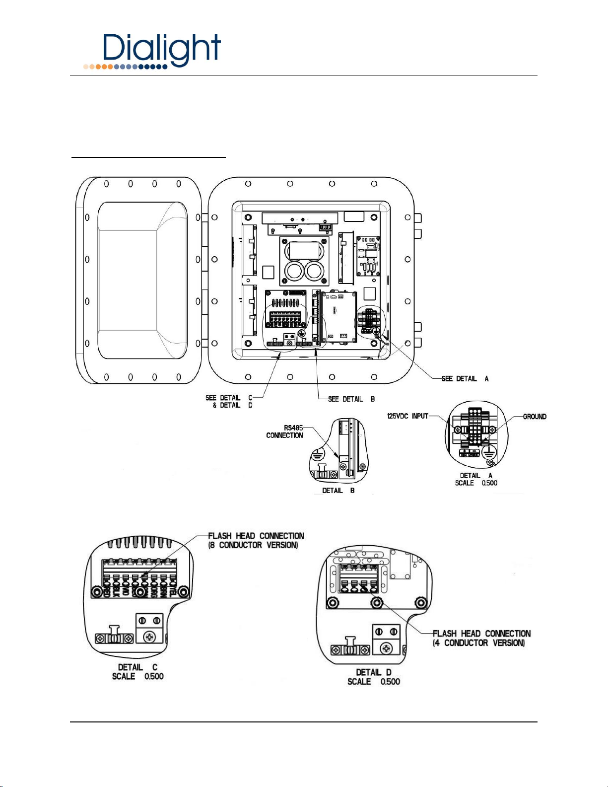
POWER SUPPLY CONNECTIONS
The Enclosure has holes drilled and tapped for all wiring connections.
WARNING: No additional holes can be added to the enclosure.
NOTE: Multiple grounding points are provided in the enclosure for protective and
functional Earth/Ground connections.
FRONT VIEW OF THE POWER SUPPLY ENCLOSURE
Entry Number
Size
For
1
3/4 NPT
Flash Head Connection
2
3/4 NPT
RS485
3
3/4 NPT
AC or DC Input and, if
needed, output*
*A conduit “T” can be used at entry 3, for additional mains output or input

Document No.
9100-127-2044-99 Rev C
Release Date: August 2020
Dialight Corporation 1501 Route 34 South Farmingdale NJ 07727
Tel: 732.919.3119 Fax: 732.751.5778 Web: www.dialight.com
Page 8 of 21
SIDE VIEW OF THE POWER SUPPLY ENCLOSURE
Installation and Wiring
WARNING: Before any service or wiring is conducted ensure the DC at the breaker is
off!!!
SYSTEM BLOCK DIAGRAM
A Com B + - GND
Multi-way connection cable (up
to 550ft) See pg. 4 for
conductor sizing
Flash
Head
AC or DC
Power In
Power Supply
Enclosure
RS485
Control
Signal
Document No.
9100-127-2044-99 Rev C
Release Date: August 2020
Dialight Corporation 1501 Route 34 South Farmingdale NJ 07727
Tel: 732.919.3119 Fax: 732.751.5778 Web: www.dialight.com
Page 9 of 21
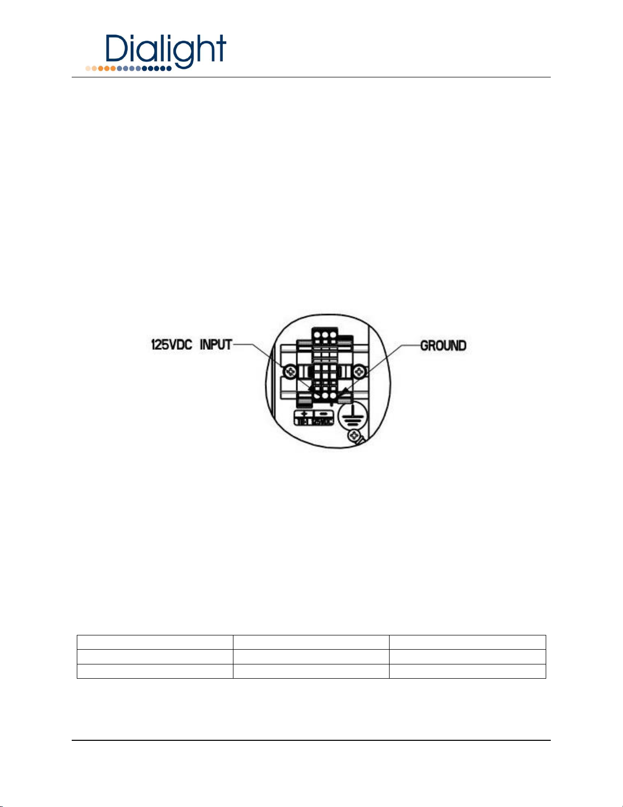
Power Supply Terminal Connection
Located at the bottom right hand side of the enclosure is the terminal block required for
connecting the Positive, Negative and Earth Ground to the power supply.
WARNING: Floating Neutrals are not permissible within the wiring of the system and the
installer must verify the connections. This will “Void” all warranties.
WARNING: Ground connection is required to provide safety and proper operation of the
system.
WARNING: There can be no more than 305Vac measured from Live to Earth ground on
TB1
NOTE: The load and voltage loss of the cable must be quantified before selecting the
cable size requirements.
DC TERMINAL BLOCK
RS485 Communication Connection
The connection of the RS485 cable is vitally important to the operation of the system.
This connection provides all the events and alarms to the Master controller that is being
used with the installation.
Factory connected wiring color code:
The RS485 consists of 3 conductors
Boards are Labeled Description Color Code
Label “A”
Communications “A”
Gray or White
Common
Common for RS485
Yellow
Label “B”
Communications “B”
Blue
Document No.
9100-127-2044-99 Rev C
Release Date: August 2020
Dialight Corporation 1501 Route 34 South Farmingdale NJ 07727
Tel: 732.919.3119 Fax: 732.751.5778 Web: www.dialight.com
Page 10 of 21
Option 1:
The RS485 consists of 3 conductors, a drain wire and either a shield or braid.
Install Cable Connected to Description Color Code
Conductor 1
Label “A”
Communications “A”
Gray or White
Conductor 2
Common
Common for RS485
Yellow
Conductor 3
Label “B”
Communications “B”
Blue
Drain wire
Ground stud
Ground
Bare wire
Shield or Braid
Clamping terminal
Ground
Connected when
cable enters the
enclosure and must
be connected to
plate
Option 1 above is applicable with RS-485 communication cable as purchased from
Dialight, part number CAB---183BFD. Where --- represents the cable length in feet.
Option 2:
When 2 Conductors, a drain wire and either a shield or braid is used.
Install Cable Connected to Description Color Code
Conductor 1
Label “A”
Communications “A”
TBD by installer
Drain Wire
Common
Common for RS485
Bare Wire
Conductor 2
Label “B”
Communications “B”
TBD by installer
Shield or Braid
Clamping Terminal
Ground
Connected when
cable enters the
enclosure and must
be connected to
plate
WARNING: For Color Codes labeled TBD the installer must take note of the colors
used for these connections since it is required that all A, Common and B terminals be
connected the same throughout the system.
Located inside the Power Enclosure to the left of the DC terminal block is the
connection point for the RS485 cable.

Document No.
9100-127-2044-99 Rev C
Release Date: August 2020
Dialight Corporation 1501 Route 34 South Farmingdale NJ 07727
Tel: 732.919.3119 Fax: 732.751.5778 Web: www.dialight.com
Page 11 of 21
TRANSLATOR & RS485 JUNCTION BOARD
NOTE: Rotary switch SW1 on the Translator must be set to a unique address for each
Power Supply connected to the Controller.
NOTE: If ordered as a system, typically SW1 will be factory set per this table (i.e. JB4-
xxxxxxxxxx would have SW1 set to Position 3). This should be confirmed by the
installer. Replacement plates will typically have SW1 set to 0; the switch must be set by
the installer to match the address that is being replaced.
SW1 Position
MIOL No.
0
1
1
2
2
3
3
4
4
5
5
6
6
7
7
8
Document No.
9100-127-2044-99 Rev C
Release Date: August 2020
Dialight Corporation 1501 Route 34 South Farmingdale NJ 07727
Tel: 732.919.3119 Fax: 732.751.5778 Web: www.dialight.com
Page 12 of 21
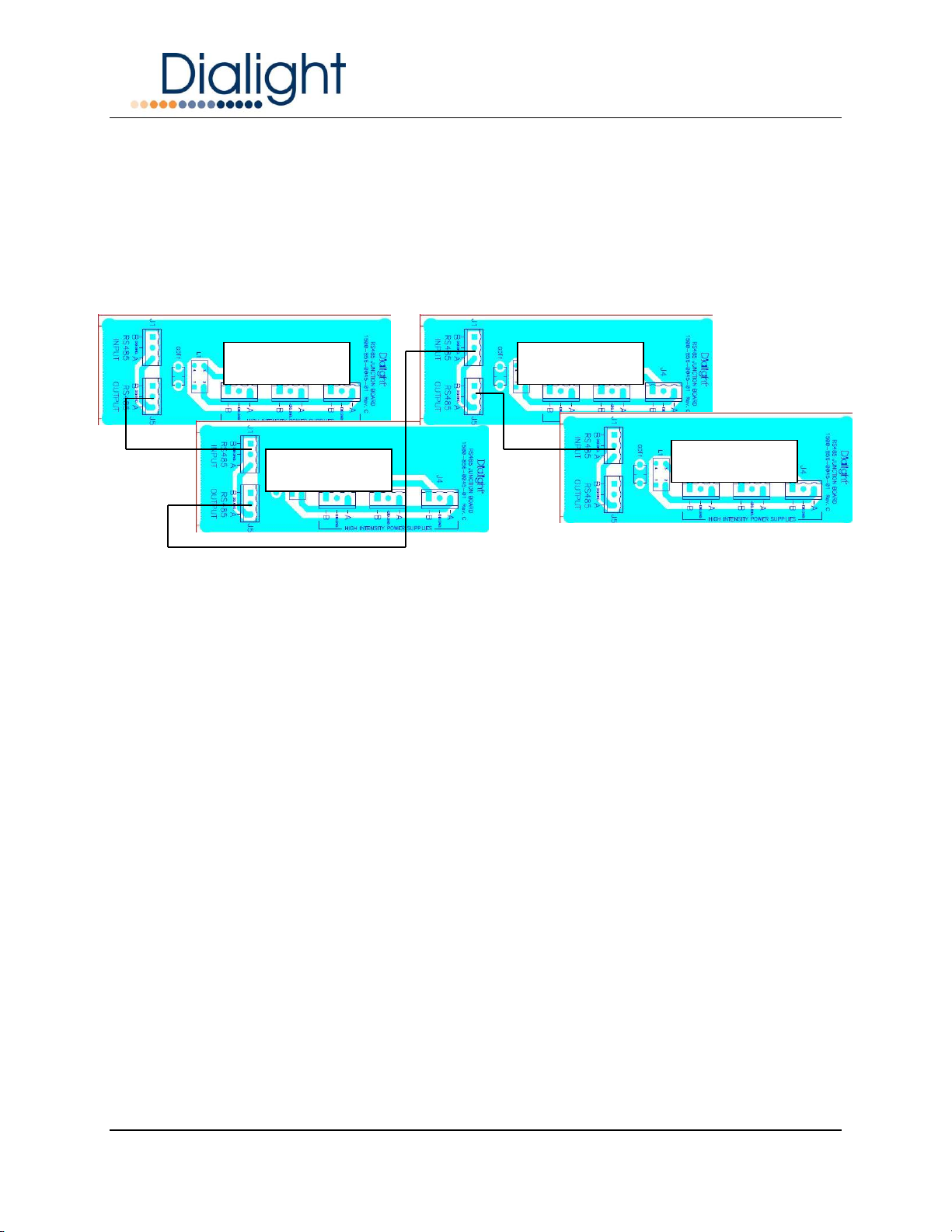
RS485 shall be connected throughout the system per the simplified diagram below.
Both the Controller and Power Supply enclosures house the same RS485 junction
board. Beginning at the Controller; it is always connected from the Output (J5) to the
Input (J1) of the next enclosure.
RS485 SYSTEM DIAGRAM
Flash Head Connection
The connection between the Flash Head and the Power Supply requires an 8 conductor
cable.
NOTE: This is the only connection to the Flash Head that is required.
WARNING: If the cable is not color coded or numbered the instructions state the
installer must take notes of wiring to ensure that both the Flash Head and Power supply
get wired the same. If for example wire 1 is inserted in to location 4 by mistake severe
damage could result to the LED’s in the flash head. This will VOID all warranties.
Pin 1 or RED in the flash head must go to Pin1 RED in the power supply and so
on.
NOTE: The installer should provide this information to the site manager upon
completion for future reference when required
Controller
P/S 1
P/S 2
P/S 3
Document No.
9100-127-2044-99 Rev C
Release Date: August 2020
Dialight Corporation 1501 Route 34 South Farmingdale NJ 07727
Tel: 732.919.3119 Fax: 732.751.5778 Web: www.dialight.com
Page 13 of 21
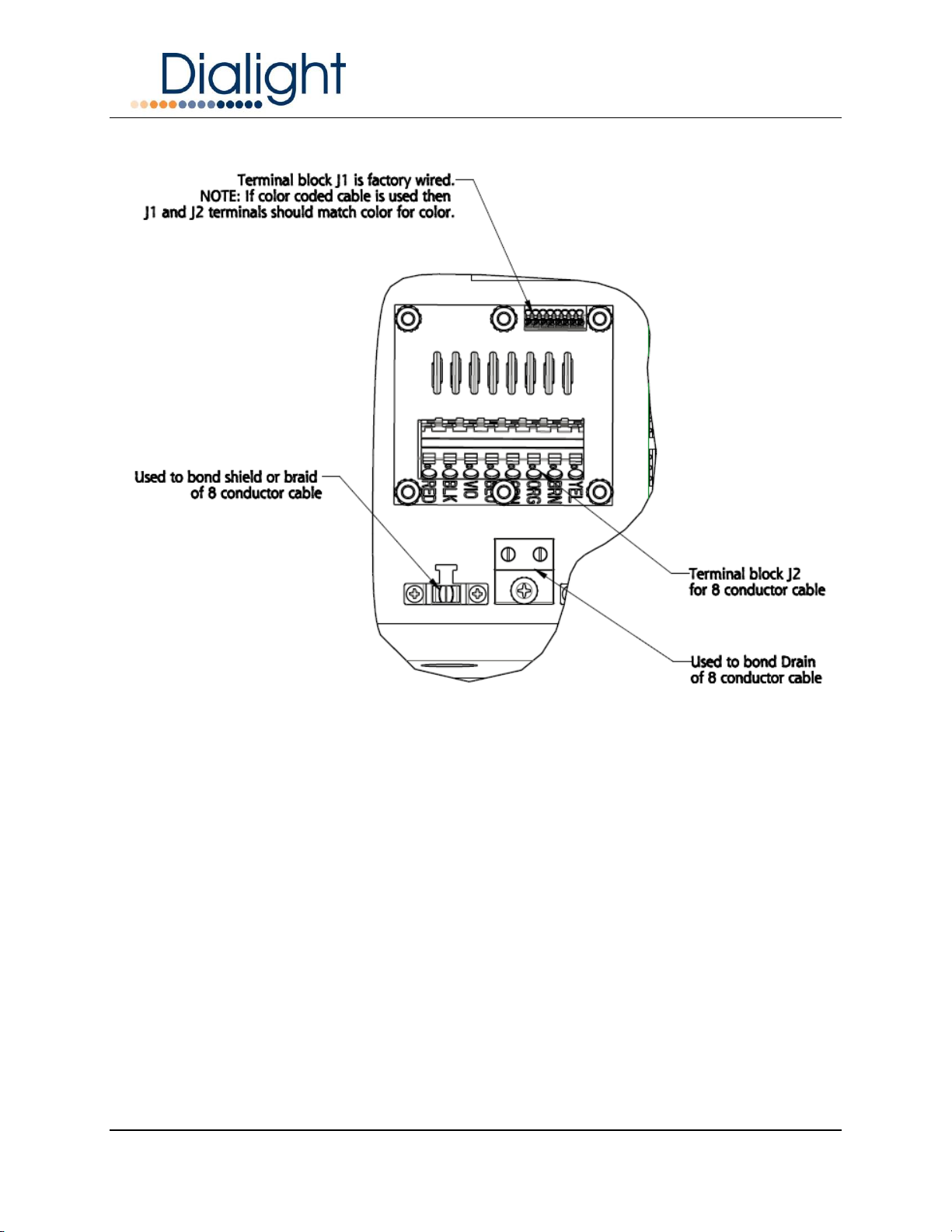
8 CONDUCTOR VERSION
FLASH HEAD CONNECTION, 8 CONDUCTOR
J2 Terminal block definitions:
NOTE: The Flash head and Power supply have the same protection board.
Two conductors are required for the Red Beacon and six for the White Strobe.
Red L864 Connections: Terminal block J2 pins 1 and 2
White L865 Connections: Terminal Block J2 pins 3 thru 8
RED (Pin1) = + (positive) for Red L864
BLK (Pin 2) = - (return) for Red L864
VIO (Pin 3) = + (positive) for White L865
BLU (Pin 4) = - (return) for White L865
GRN (Pin 5) = - (return) for White L865
ORG (Pin 6) = + (positive) for White L865
BRN (Pin 7) = - (return) for White L865
YEL (Pin 8) = - (return) for White L865

Document No.
9100-127-2044-99 Rev C
Release Date: August 2020
Dialight Corporation 1501 Route 34 South Farmingdale NJ 07727
Tel: 732.919.3119 Fax: 732.751.5778 Web: www.dialight.com
Page 14 of 21
4 CONDUCTOR VERSION
FLASH HEAD CONNECTION, 8 CONDUCTOR
J2 Terminal block definitions:
NOTE: The Flash head and Power supply have the same protection board.
Two conductors are required for the Red Beacon and two for the White Strobe.
Red L864 Connections: Terminal block J2 pins 1 and 2
White L865 Connections: Terminal Block J2 pins 3 and 4
RED/BLACK (Pin1) = - (NEGATIVE) for Red L864
RED (Pin 2) = + (POSITIVE) for Red L864
WHITE/BLACK (Pin 3) = - (NEGATIVE) for White L865
WHITE (Pin 4) = + (POSITIVE) for White L865
WARNING: Take care to connect correctly, as incorrect operation can cause
damage to the driver modules.

Document No.
9100-127-2044-99 Rev C
Release Date: August 2020
Dialight Corporation 1501 Route 34 South Farmingdale NJ 07727
Tel: 732.919.3119 Fax: 732.751.5778 Web: www.dialight.com
Page 15 of 21
System Installation Requirements for EMC and Lightning Immunity:
1: Ensure the shield of the cable that connects the Flash head to the power supply is
grounded at both ends. Make 360-degree ground connections around the braid or foil
(avoid pigtails).
2: For increased lightning protection adding a lightning rod that extends up 3 feet above
the fixture and 18 inches away from the light is recommended.
3: The drain-wire in the Flash Head cable must be connected to ground at both ends.
Ensure that the wire is short as possible and avoid loops.
4: Ensure the Flash Head is electrically bonded to the tower. Scrape away access paint/
powder coating as necessary.
5: Minimize loop areas by tying all cables against the tower or passing through conduit.
6: Ensure the Power Supply enclosure is electrically bonded to the tower. Scrape away
access paint/ powder coating as necessary.
7: Ground any spare/unused conductors in the Flash Head connection cable at both
ends.
8: It is recommended that a minimum of ¾” conduit is used for all wiring ways.
9: RS485 connections must be secure and shield or braiding must be grounded
securely.
Power Supply Specifications & Electrical Parameters:
Flash Rate for L864/L865
The Red Beacon factory setting is 30FPM (Flash per minute).
The White Strobe factory setting is 40 FPM (Flash per minute).
Fault / Alarm Connections
There are NO additional fault connections required in the Power Supply enclosure. All
faults are sent to the Base controller via the RS485 communications.
NOTE: It is vitally important that the RS485 connections are checked and secured.

Document No.
9100-127-2044-99 Rev C
Release Date: August 2020
Dialight Corporation 1501 Route 34 South Farmingdale NJ 07727
Tel: 732.919.3119 Fax: 732.751.5778 Web: www.dialight.com
Page 16 of 21
Configuration Option Switches
NOTE: In previous versions of the Dialight D1RW there were settings required for the
dip switches on the micro board.
This version only requires position 1 of SW1 to be used.
If being used as a Dual red and white beacon the micro board switches SW1 must be
set to the off position.
If being used as a White only system then SW1 position 1 should be set to the on
position.
NOTE: The switches are factory set to the off position and positions 2, 3, & 4 should be
checked that they are set in the off position.
Micro / Filter Assembly Image
Capacitor Voltage Indication
Safety Warning
This unit holds a number of large capacitors for storage of the energy required
during the Strobe’s flash duration. These capacitors may be charged with
voltages up to 185Vdc. Associated with each capacitor is a red indicator LED.
When lit, this indicates the capacitor voltage is 50V or higher. When power is
removed from the module the capacitors automatically discharge to 50V within 30
seconds.
Do not attempt any maintenance or wiring until the capacitors have been allowed
time to discharge to a safe level and all red indicator LED’s have gone out.
SW1
Up is on towards
Black connectors
Down is off
Position 1
Position 4

Document No.
9100-127-2044-99 Rev C
Release Date: August 2020
Dialight Corporation 1501 Route 34 South Farmingdale NJ 07727
Tel: 732.919.3119 Fax: 732.751.5778 Web: www.dialight.com
Page 17 of 21
Strobe White Driver Diagnostic LED’s
The two Strobe White Driver modules each have three indicator LED’s.
LED 2 and 3: Each is driven from one of the driver’s three outputs. Therefore normally
each one should blink at the same rate as the Strobe output. These indicate the driver
module is operating. If for some reason some of the White LED’s in the Flash Head do
not operate yet these diagnostic LED’s do blink, this would indicate the fault is not with
the Driver module. Should one or more of these LED’s be stuck on or not flash at all,
this may indicate a fault with the driver module.
LED 4: Lights continuously when the Strobe is energized to show that an excess of 50V
is present at its output. If this does not light it might indicate either the Driver module is
faulty or not receiving any power.
Red Beacon Driver Diagnostic LED
LED 1: Indicates more than 50V is present on the output and gives a good indication
that the Beacon Driver module is working.
Microcontroller Board Diagnostic LED’s
LED 1 (Red) on the Microcontroller board shows the status of the Flash Head. In white
mode, it will flash the driver number of any white drivers that currently have faulty
strings. In red mode, it will flash once every two seconds if the red current is low and
twice if the current is too high. It will not flash at all when all drivers are operating
properly.
LED 2 (Green) on the Microcontroller board pulses once every time a flash is initiated in
the Flash Head.
NOTE: Verification of the above may only be required if a communications Alarm is sent
to the Master Controller
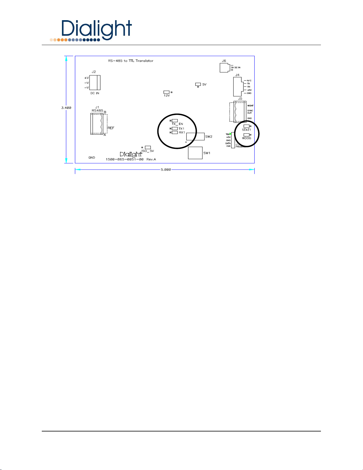
Translator Board Diagnostic LED’s
When power is applied to the Power Supply there are 3 LED’s labeled ISO 5V, 12V and
5V that must be solidly lit. The LED labeled Watchdog must be blinking.
Once communications from the Master controller has been established there 3 LED’s
that will Blink in unison.
These are TX_EN, TX 1 and RX 1
NOTE: If these are not blinking then there are no Communications.
NOTE: SW1 must be to set to position 0 when used as an AOL

Document No.
9100-127-2044-99 Rev C
Release Date: August 2020
Dialight Corporation 1501 Route 34 South Farmingdale NJ 07727
Tel: 732.919.3119 Fax: 732.751.5778 Web: www.dialight.com
Page 18 of 21
J1 is the connection point for the incoming RS485 cable, ports B (Pin1) and A (Pin3)
can be seen. The Common connection point is the center pin 2.
Translator Indicators
Translator Communications LED’s:
Once communication has begun LED’s labeled TX_EN, TX1 and RX1 will begin to
flash.
LED marked “watchdog” will also blink approx. every half second.
STAT1 LED will be solidly lit.
Pin3 (+)
Pin 2 (-)
Pin 1 (-)
Square on bottom of
board is always pin1
LED
indicators
Must be
steady on
Document No.
9100-127-2044-99 Rev C
Release Date: August 2020
Dialight Corporation 1501 Route 34 South Farmingdale NJ 07727
Tel: 732.919.3119 Fax: 732.751.5778 Web: www.dialight.com
Page 19 of 21
Translator Indicators
Document No.
9100-127-2044-99 Rev C
Release Date: August 2020
Dialight Corporation 1501 Route 34 South Farmingdale NJ 07727
Tel: 732.919.3119 Fax: 732.751.5778 Web: www.dialight.com
Page 20 of 21
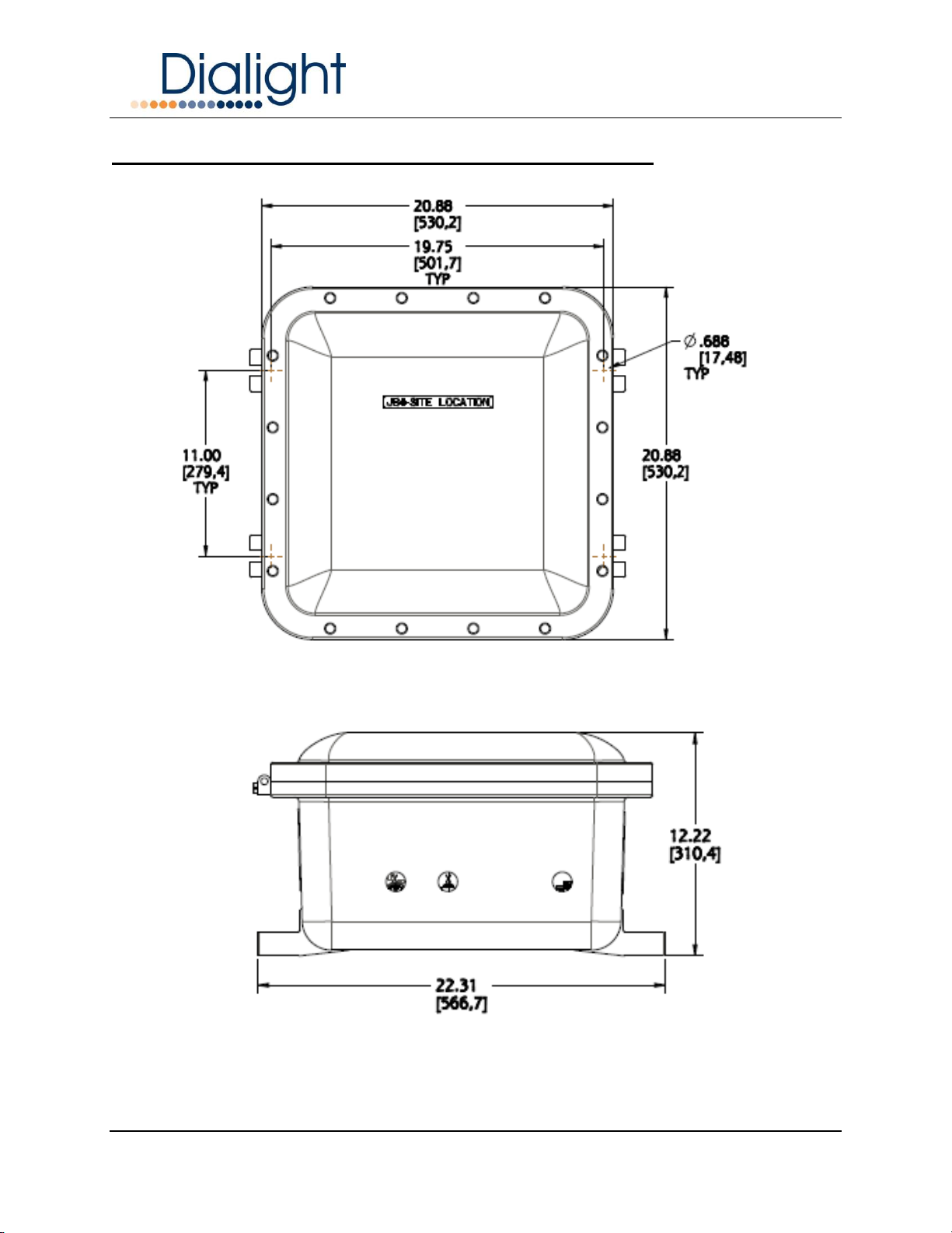
Mechanical Dimensions of Power Supply Enclosure:
Enclosure dimensions
This manual suits for next models
5
Table of contents
Popular Power Supply manuals by other brands


Intelligent Motion Systems
Intelligent Motion Systems ISP300 datasheet

KTI Networks
KTI Networks KPW-1012-D user manual

Allen-Bradley
Allen-Bradley 1606-XLE480EP installation instructions

Scientific
Scientific PSD7303A user manual

Matsusada Precision
Matsusada Precision DOPF Series instruction manual

Cooper Wheelock
Cooper Wheelock POWERPATH PS-24-8MC installation instructions


