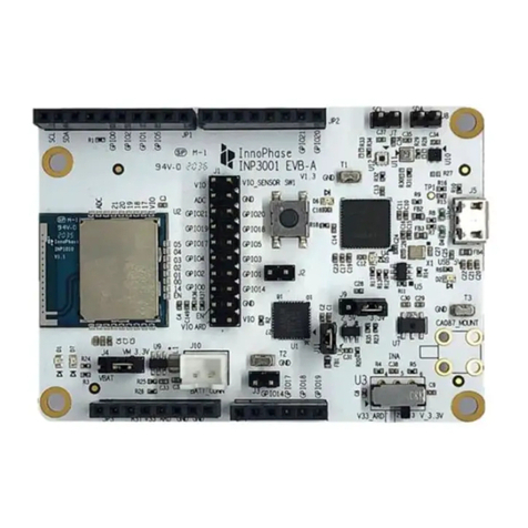
Dialog Semiconductor SMARTBOND TINY DA14531 Instructions for use

DA14531 SMARTBOND TINY™ MODULE Development
Kit Hardware User Manual
Target
DA14531 SMARTBOND TINY™
MODULE Development Kit
Hardware User Manual
UM-B-141
Abstract
This document outlines the system design, configuration options and supported features of DA14531
SMARTBOND TINY™ MODULE Development Kit, PCB version 376-25-C.

UM-B-141
DA14531 SMARTBOND TINY™ MODULE Development
Kit Hardware User Manual
Target
User Manual
Revision 1.1
11-05-2020
CFR0012
2 of 29
© 2020 Dialog Semiconductor
Contents
Abstract................................................................................................................................................ 1
1Terms and Definitions................................................................................................................... 4
2References..................................................................................................................................... 4
3Introduction.................................................................................................................................... 5
4System Overview........................................................................................................................... 6
4.1 Features................................................................................................................................6
4.2 System and components description....................................................................................7
4.3 Block Diagram..................................................................................................................... 10
5DA14531 SmartBond TINY™ Module Daughterboard ............................................................. 11
5.1 Power Section..................................................................................................................... 11
5.1.1 Default Power Supply Option Configuration........................................................ 11
5.1.2 Optional USB power section................................................................................ 12
5.2 Reset operation...................................................................................................................12
5.3 General Purpose Buttons.................................................................................................... 12
5.4 General Purpose LEDs.......................................................................................................13
5.5 MikroBUS™ Module............................................................................................................14
5.6 JTAG................................................................................................................................... 16
5.7 UART...................................................................................................................................17
5.8 GPIOs and pin assignment on DA14531 SMARTBOND TINY™ MODULE DB ................ 17
5.9 Programming and debugging interface setup..................................................................... 19
5.9.1 Single wire UART, JTAG, RESET....................................................................... 20
5.9.2 2-wire UART, JTAG, RESET............................................................................... 21
5.9.3 4-wire UART, JTAG, RESET............................................................................... 21
5.10 First Steps with DA14531 SMARTBOND TINY™ MODULE DEVKIT................................ 23
6Known Issues .............................................................................................................................. 24
6.1 Keil JTAG default Clock Speed........................................................................................... 24
Appendix A......................................................................................................................................... 26
A.1 Schematic ...........................................................................................................................26
A.2 Placed Components............................................................................................................27
Revision History................................................................................................................................ 28
Figures
Figure 1: DA14531 SMARTBOND TINY™ MODULE DB..................................................................... 5
Figure 2: DA14531 SMARTBOND TINY™ MODULE DEVKIT............................................................. 6
Figure 3: Component description. Top side. ......................................................................................... 7
Figure 4: Component description. Bottom side..................................................................................... 8
Figure 5: DA14531 SMARTBOND TINY™ MODULE DB Block Diagram .......................................... 10
Figure 6: Power option selection for DA14531 SMARTBOND TINY™ MODULE DB ........................ 11
Figure 7: Power option default configuration....................................................................................... 11
Figure 8: Optional USB power supply section..................................................................................... 12
Figure 9: Reset Button on DA14531 SMARTBOND TINY™ MODULE DB........................................ 12
Figure 10: General purpose push buttons on DA14531 SMARTBOND TINY™ MODULE DB .......... 13

UM-B-141
DA14531 SMARTBOND TINY™ MODULE Development
Kit Hardware User Manual
Target
User Manual
Revision 1.1
11-05-2020
CFR0012
3 of 29
© 2020 Dialog Semiconductor
Figure 11: Default general purpose push button (SW2) on DA14531 SMARTBOND TINY™ MODULE
DB........................................................................................................................................................ 13
Figure 12: SW2 configuration on DA145xx DEVKT-P PRO-MB......................................................... 13
Figure 13: General Purpose LEDs on DA14531 SMARTBOND TINY™ MODULE DB...................... 14
Figure 14: Default LED on DA14531 SMARTBOND TINY™ MODULE DB ....................................... 14
Figure 15: D5 LED configuration on DA145xx DEVKT-P PRO-MB.................................................... 14
Figure 16: Default programming interface of MikroBUS™ module on DA14531 SMARTBOND TINY™
MODULE DB....................................................................................................................................... 15
Figure 17: MikroBUS™ module Socket on DA14531 SMARTBOND TINY™ MODULE DB.............. 15
Figure 18: Example of mounting MikroBUS™ module........................................................................ 16
Figure 19: Optional debug port............................................................................................................ 16
Figure 20: DA145xx DEVKT-P PRO-MB jumper setup for Single wire UART, JTAG and RESET
operation.............................................................................................................................................. 20
Figure 21: DA145xx DEVKT-P PRO-MB jumper setup for 2-wire UART, JTAG and RESET operation
............................................................................................................................................................. 21
Figure 22: DA145xx DEVKT-P PRO-MB jumper setup for 4-wire UART, JTAG and RESET operation
............................................................................................................................................................. 22
Figure 23: DA145xx DEVKT-P PRO-MB First Steps Jumper Configuration with DA14531
SMARTBOND TINY™ MODULE DB attached ................................................................................... 23
Figure 24: Keil reporting error when try to open debugger session.................................................... 24
Figure 25: Steps to set up JTAG clock speed..................................................................................... 24
Figure 26: Schematic of DA14531 SMARTBOND TINY™ MODULE DB [376-25-C]......................... 26
Figure 27: Components on top and bottom sides for DA14531 SMARTBOND TINY™ MODULE DB
[376-25-C]............................................................................................................................................ 27
Tables
Table 1: Test Points Description ........................................................................................................... 8
Table 2: MikroBUS™ GPIOs multiplexing........................................................................................... 15
Table 3: JTAG signals assignment...................................................................................................... 16
Table 4: DA14531 SMARTBOND TINY™ MODULE DB UART Signals ............................................ 17
Table 5: GPIO multiplexing on DA14531 SMARTBOND TINY™ MODULE DB................................. 17
Table 6: Power, SPI Flash and programming/debugging jumper setup of DA145xx DEVKT-P PRO-
MB for TINY™ MODULE..................................................................................................................... 19
Table 7: Pin assignment for DA14531 SMARTBOND TINY™ MODULE Configuration 1 ................. 20
Table 8: Pin assignment for DA14531 SMARTBOND TINY™ MODULE configuration 2 .................. 21
Table 9: Pin assignment for DA14531 SMARTBOND TINY™ MODULE configuration 3 .................. 21

UM-B-141
DA14531 SMARTBOND TINY™ MODULE Development
Kit Hardware User Manual
Target
User Manual
Revision 1.1
11-05-2020
CFR0012
4 of 29
© 2020 Dialog Semiconductor
1 Terms and Definitions
DEVKIT Development Kit
DB Daughterboard
USB Universal Serial Bus
JTAG Join Test Action Group
UART Universal Asynchronous Receiver-Transmitter
SDK Software Development Kit
SoC System on Chip
GPIO General Purpose Input Output
LDO Low Dropout
QSPI Quad Serial Peripheral Interface
SPI Serial Peripheral Interface
I2C Inter-Integrated Circuit
SMD Surface-Mount Device
PCB Printed Circuit Board
2 References
[1] UM-B-114, DA14531_Devkit_Pro_Hardware_User_manual, Revision 1.1, Dialog
Semiconductor.
[2] DA14531MOD_Datasheet_v1.0, Datasheet, Revision 1.0, Dialog Semiconductor.
[3] DA14531_datasheet_3v0, Datasheet, Revision 3.0, Dialog Semiconductor

UM-B-141
DA14531 SMARTBOND TINY™ MODULE Development
Kit Hardware User Manual
Target
User Manual
Revision 1.1
11-05-2020
CFR0012
5 of 29
© 2020 Dialog Semiconductor
3 Introduction
This document describes the DA14531 SMARTBOND TINY™ MODULE Development Kit. The
development kit is implemented on a single Daughterboard (DB) PCB and it comes with DA145xx
DEVKT-P PRO-MB for SW development, programming, debugging and measuring current but also
can be used stand alone.
The block diagram, the actual board, the various sections and settings as well as the connectivity are
presented. The purpose of this Daughterboard is to provide users with the capability for:
●Access to the DA14531 SMARTBOND TINY™ MODULE, via UART or JTAG
●Connecting MikroBUS™ module
●User access to general purpose LED(s)
●User access general purpose button(s)
●Reset button
●Test points for all output signals
●Stand-alone operation
Figure 1: DA14531 SMARTBOND TINY™ MODULE DB

UM-B-141
DA14531 SMARTBOND TINY™ MODULE Development
Kit Hardware User Manual
Target
User Manual
Revision 1.1
11-05-2020
CFR0012
6 of 29
© 2020 Dialog Semiconductor
Figure 2: DA14531 SMARTBOND TINY™ MODULE DEVKIT
4 System Overview
4.1 Features
The features of DA14531 SMARTBOND TINY™ MODULE DB include:
●Integrated Dialog Semiconductor DA14531 SMARTBOND TINY™ MODULE
●Reset push button (SW3)
●A set of general-purpose LED and button (LED1 and SW2)
●Supply from VLDO (3V) from DA145xx DEVKT-P PRO-MB or from coin cell battery
●Capability of mounting a MikroBUS™module (J3, J4)
●JTAG and UART interface over DA145xx DEVKT-P PRO-MB
●JTAG and UART interface over on-board header (J2)
●Stand-alone operation
●A dimension of 58.43x44.46 mm
●Optional features:
○Power supply option from USB connector (only for power not for debugging). User must
solder the components.

UM-B-141
DA14531 SMARTBOND TINY™ MODULE Development
Kit Hardware User Manual
Target
User Manual
Revision 1.1
11-05-2020
CFR0012
7 of 29
© 2020 Dialog Semiconductor
○Location on board for a second set of LED and button (LED2 and SW1). User must solder the
components.
4.2 System and components description
Figure 3: Component description. Top side.
The marked and numbered sections of the system are:
1. DA14531 SMARTBOND TINY™ MODULE (U1)
2. Reset button (SW3/RESET)
3. General purpose LED (D2)
4. General purpose button (SW2)
5. JTAG debugger connector (J2)
6. GND pad (TP26)
7. Power supply configuration resistor (VLDO of PRO-MB/ Coin cell battery or USB)
8. MikroBUS™connection points (J3, J4)
9. MikroBUS™configuration resistors for I2C interface
10. MikroBUS™configuration resistors for SPI interface

UM-B-141
DA14531 SMARTBOND TINY™ MODULE Development
Kit Hardware User Manual
Target
User Manual
Revision 1.1
11-05-2020
CFR0012
8 of 29
© 2020 Dialog Semiconductor
11. Power switch (SW4). Selection between VLDO from PRO-MB/ Coin cell battery or USB power
supply. Optional.
12. USB power supply section with OVP circuit. Optional.
13. Jumper header for LED isolation(J5). Optional.
14. General purpose button (SW1). Optional.
15. General purpose LED (D1). Optional.
16. Mating connector on the PCB (J1).
Figure 4: Component description. Bottom side.
The bottom side of the kit provides battery case for a CR2032 coin cell battery. Test points have
been placed for monitoring various signal behaviors and voltage levels of the components. The
marked and numbered sections of the system are:
17. Coin cell battery (BT1)
18. Test points (see Table 1 for more details)
19. Dialog label
Table 1: Test Points Description
Test Point
Assigned to
Comments
TP1
FIDUCIAL
Not electrically connected
TP2
FIDUCIAL
Not electrically connected
TP3
GND
Ground
TP7
SWCLK
JTAG Interface- Clock Signal
TP8
VLED1
Voltage level of RED LED (D1)
TP9
SWDIO
JTAG Interface DIO Signal

UM-B-141
DA14531 SMARTBOND TINY™ MODULE Development
Kit Hardware User Manual
Target
User Manual
Revision 1.1
11-05-2020
CFR0012
9 of 29
© 2020 Dialog Semiconductor
Test Point
Assigned to
Comments
TP10
VLED2
Voltage Level of Green LED (D2)
TP12
RESET
Reset
TP13
SW1
General purpose button (driven from P0_6 signal)
TP14
SW2
General purpose button (driven from P0_11 signal)
TP15
SW3
Reset button (driven from P0_0 signal)
TP16
MikroBUS™LOGO
Not electrically connected
TP18
5V
USB +5V voltage level after OVP circuit
TP19
VBUS_IN
USB +5V voltage level
TP20
VLDO
LDO (U2) 3.3V output voltage level
TP21
VBAT_MOD
Power supply rail of DA14531 SMARTBOND TINY™
MODULE
TP22
VBAT
Power supply rail of VLDO of DA145xx DEVKT-P PRO-MB or
external coin cell battery
TP23
ESD_WARNING SIGN
Not electrically connected
TP24
GND
Ground
TP25
GND
Ground
TP26
GND
Ground
TP27
URX
4-wire UART RX Signal
TP28
UTX
4-wire UART TX Signal
TP29
UCTS
4-wire UART CTS Signal
TP30
URTS
4-wire UART RTS Signal

UM-B-141
DA14531 SMARTBOND TINY™ MODULE Development
Kit Hardware User Manual
Target
User Manual
Revision 1.1
11-05-2020
CFR0012
10 of 29
© 2020 Dialog Semiconductor
4.3 Block Diagram
Figure 5: DA14531 SMARTBOND TINY™ MODULE DB Block Diagram
DA14531
SmartBond Tiny
(U1)
P0_2
P0_5
P0_6
P0_7
P0_8
P0_9
P0_11
P0_0
VBAT
P0_10
VLDO
VBAT_MOD
5V
J6=NP
mini USB
Connector
SW4=NP
VBAT
5V
R41=0 Ohm
R42=NP
Power supply section
RESET/
SPI/I2C
SW3
Buttons
SW1=NP
SW2
P0_6
P0_11
General Purpose Buttons
LEDs
OVP
(NP) U2 LDO
3.3V (NP)
Reset
D1=NP
D2
J5=NP
R40
R39=NP
General Purpose LEDs
P0_8
P0_9
V3 DA14531 PRO-MB
LDO(U5)
Coin Cell (BT1)
P0_0/RST
MikroBUS
P0_7
P0_8
P0_6
P0_11
P0_9
R=NP RST
CS
SCK
MISO
MOSI
INT
SCL
SDA
P0_7
P0_6
P0_11
J3 J4
P2_0,2,5,6,7,8,9
P3_0,1
P0_4,5,6,7
JTAG
4-wire UART/Single UART
SWDIO
URx
RxTx
RESET
P2_2
P2_8
P3_1
J1-mating
connector on PCB
R-Multiplexer
Not populated
JTAG/2-WIRE
URx/P0_5
J2
SWCLK SWDIO
Reset
UTx/P0_6
On Board Debugger Connector

UM-B-141
DA14531 SMARTBOND TINY™ MODULE Development
Kit Hardware User Manual
Target
User Manual
Revision 1.1
11-05-2020
CFR0012
11 of 29
© 2020 Dialog Semiconductor
5 DA14531 SmartBond TINY™ Module Daughterboard
5.1 Power Section
The power supply on the DA14531 SMARTBOND TINY™ MODULE DB supports three options:
●Power supply from DA145xx DEVKT-P PRO-MB. The supply voltage comes from VLDO setup
(U5) with output voltage range to meet recommended operating conditions of DA14531
SmartBond TINY™ Module. See [2] for recommended operating conditions and Table 6 for
VLDO selection.
●Power supply from Coin cell battery (BT1). Battery case is mounted on bottom side of the
daughterboard. Notice: User must not mount coin cell battery when daughterboard is
supplied from DA145xx DEVKT-P PRO-MB.
●+5V USB Power Supply (J6 connector) with Over Voltage Protection Circuit (OVP). Optional.
Using power supply from VLDO of DA145xx DEVKT-P PRO-MB, allows user to measure Current
drawn from the DA14531 SmartBond TINY™ Module by using the current sensing circuit and the
power profiler of Dialog’s SmartSnippets Toolbox. For more information regarding current
measurement refer to [1].
5.1.1 Default Power Supply Option Configuration
Power selection between DA145xx DEVKT-P PRO-MB VLDO/ Coin Cell battery and USB Power
Supply is done in two ways:
●Using resistors R41, R42:
○R41 - Power supply from DA145xx DEVKT-P PRO-MB / Coin Cell. Default configuration.
○R42 - VLDO (3.3V) of USB power section. Optional.
●Using SW4 power switch. Optional.
Figure 6: Power option selection for DA14531 SMARTBOND TINY™ MODULE DB
Figure 7: Power option default configuration

UM-B-141
DA14531 SMARTBOND TINY™ MODULE Development
Kit Hardware User Manual
Target
User Manual
Revision 1.1
11-05-2020
CFR0012
12 of 29
© 2020 Dialog Semiconductor
5.1.2 Optional USB power section
USB power section consists of the following parts:
–Mini Type B USB connector (J6)
–OVP circuit
–LDO (3.3V) regulator (U2)
USB power section is not populated.
Figure 8: Optional USB power supply section
5.2 Reset operation
Reset operation on the DA14531 SMARTBOND TINY™ MODULE can be activated with one of the
following ways:
●By pressing the on board RESET button (SW3)
●Through software from the UART & JTAG interface of DA145xx DEVKT-P PRO-MB
●By pressing RESET button on DA145xx DEVKT-P PRO-MB (SW1)
Reset signal is connected to P0_0.
Figure 9: Reset Button on DA14531 SMARTBOND TINY™ MODULE DB
5.3 General Purpose Buttons
Push button SW2 is populated and placed on top side of the board (Figure 11). It is connected to
P0_11(Figure 10) and shares the same configuration with SW2 button of DA145xx DEVKT-P PRO-
MB (SW2 is connected to P3_1 on the motherboard which is P0_11 on DA14531).See Figure 12.
SW1 is not populated (Figure 11). It is connected to P0_6 (Figure 10).

UM-B-141
DA14531 SMARTBOND TINY™ MODULE Development
Kit Hardware User Manual
Target
User Manual
Revision 1.1
11-05-2020
CFR0012
13 of 29
© 2020 Dialog Semiconductor
Figure 10: General purpose push buttons on DA14531 SMARTBOND TINY™ MODULE DB
Figure 11: Default general purpose push button (SW2) on DA14531 SMARTBOND TINY™
MODULE DB
Figure 12: SW2 configuration on DA145xx DEVKT-P PRO-MB
5.4 General Purpose LEDs
LED D2 is a general-purpose LED and it is driven by P0_9. LED D2 shares same configuration as
LED D5 of DA145xx DEVKT-P PRO-MB (D5 is driven by P1_0 of motherboard which is P0_9 of
DA14531). See Figure 15.
LED D1 is driven by P0_8 and it is not populated. User can mount a LED like D2.
General purpose LEDs circuitry is completed with Jumper header J5. J5 is optional and it isolates
signals P0_8 and P0_9 when LEDs function is not used, so signals can be directed to other
functions.

UM-B-141
DA14531 SMARTBOND TINY™ MODULE Development
Kit Hardware User Manual
Target
User Manual
Revision 1.1
11-05-2020
CFR0012
14 of 29
© 2020 Dialog Semiconductor
Header J5 by default is not populated. Instead resistors R39 and R40 are used in order to configure
the connection of LEDs to the signals (Figure 13, Figure 14).
Figure 13: General Purpose LEDs on DA14531 SMARTBOND TINY™ MODULE DB
Figure 14: Default LED on DA14531 SMARTBOND TINY™ MODULE DB
Figure 15: D5 LED configuration on DA145xx DEVKT-P PRO-MB
5.5 MikroBUS™ Module
The DA14531 SMARTBOND TINY™ MODULE DB can support MikroBUS™modules. It requires
some level of GPIOs multiplexing to avoid conflict with other functions driven by same GPIOs.
A MikroBUS™module requires a power supply of 5V, 3.3V or both, depending on the module. The
current configuration of the daughterboard supports only 3.3V. If a voltage of 5V is required, then
USB power section needs to be populated.

UM-B-141
DA14531 SMARTBOND TINY™ MODULE Development
Kit Hardware User Manual
Target
User Manual
Revision 1.1
11-05-2020
CFR0012
15 of 29
© 2020 Dialog Semiconductor
Signals available for MikroBUS™module can be seen in the Table 2. I2C signals and INT are the
default configuration for the MikroBUS™module. For SPI interface and RST additional resistors
must be populated (Figure 16, Figure 17).
DA14531 SMARTBOND TINY™ MODULE DB MikroBUS™doesn’t share same GPIO signals as
DA145xxx DEVKT-P PRO-MB MikroBUS™.
Figure 16: Default programming interface of MikroBUS™ module on DA14531 SMARTBOND
TINY™ MODULE DB
Figure 17: MikroBUS™ module Socket on DA14531 SMARTBOND TINY™ MODULE DB
Table 2: MikroBUS™GPIOs multiplexing
MikroBUS™
DA14531 SMARTBOND TINY™
MODULE GPIOs
Peripherals
I2C
SPI
Other
P0_6
SW1
SCK
P0_11
SW2
SDA (default)
MISO
P0_8
LED D1
SCL (default)
CS
P0_9
LED D2
MOSI
P0_7
INT (default)
RST

UM-B-141
DA14531 SMARTBOND TINY™ MODULE Development
Kit Hardware User Manual
Target
User Manual
Revision 1.1
11-05-2020
CFR0012
16 of 29
© 2020 Dialog Semiconductor
Figure 18: Example of mounting MikroBUS™ module
5.6 JTAG
DA14531 SMARTBOND TINY™ MODULE DB provides JTAG interface with SWDIO and SWCLK
signals assigned to P0_2 and P0_10 (Table 3). JTAG signals are also available on header J2 (Figure
19).
Table 3: JTAG signals assignment
Function
The Signals
DA145xx DEVKT-P
PRO-MB
DA14531 SMARTBOND TINY™
MODULE DEVKIT
Enabled by Jumpers (on PRO-MB)
J2
DA14531 SMARTBOND TINY™
MODULE
SW_CLK
J1:21-22 (Default)
SWCLK
P0_2
SW_DIO
J1:23-24 (Default)
SWDIO
P0_10
Figure 19: Optional debug port

UM-B-141
DA14531 SMARTBOND TINY™ MODULE Development
Kit Hardware User Manual
Target
User Manual
Revision 1.1
11-05-2020
CFR0012
17 of 29
© 2020 Dialog Semiconductor
5.7 UART
Three modes of UART can be used: single wire UART, 2 wire-UART or full UART.
Table 4: DA14531 SMARTBOND TINY™ MODULE DB UART Signals
Function
The signals
DA145xx DEVKT-P PRO-
MB
DA14531 SMARTBOND
TINY™ MODULE DB
J2
J1
DA14531 SMARTBOND
TINY™ MODULE
UTX
2-wire or Full UART Transmit
P2_6
P0_4
P0_6
URX
2-wire or Full UART Receive
P2_5
P0_5
P0_5
UCTS
2-wire or Full UART Clear to Send
P2_8
P0_6
P0_8
URTS
2-wire or Full UART Request to Send
P2_7
P0_7
P0_7
RxTx
Single wire UART Receive and Transmit
P2_5
P2_5
P0_5
Note 1 UART signals are directly mapped to J1 connector of DA145xx DEVKT-P PRO-MB: Rx, Tx, RTS and
CTS.
For enabling the different configurations check section 5.8.
5.8 GPIOs and pin assignment on DA14531 SMARTBOND TINY™ MODULE
DB
The DA14531 SMARTBOND TINY™ MODULE DB comes in with a pre-defined default configuration.
However, due to the low GPIO pin count, several functions are multiplexed and can be enabled as
needed.
On Table 5 DA14531 SMARTBOND TINY™ MODULE GPIOs use on the various functions can be
found. On the last column of the table users can check which of the functions are enabled by default
with the default hardware setup and which require some hardware modification by adding resistors.
Table 5: GPIO multiplexing on DA14531 SMARTBOND TINY™ MODULE DB
DA14531
SMARTBOND
TINY™
MODULE
Signals
J1
connector
Daughterboard
Function
1
Function 2
Function 3
Comments for functions
supported
P0_0
SW3
(RESET
Button)
Default
MB2_0
RESET
RESET on
J2 JTAG
connector
Default
Default
P0_2
MB2_2
SWCLK
SWCLK
JTAG
connector
(J2)
Default
Default

UM-B-141
DA14531 SMARTBOND TINY™ MODULE Development
Kit Hardware User Manual
Target
User Manual
Revision 1.1
11-05-2020
CFR0012
18 of 29
© 2020 Dialog Semiconductor
DA14531
SMARTBOND
TINY™
MODULE
Signals
J1
connector
Daughterboard
Function
1
Function 2
Function 3
Comments for functions
supported
P0_5
URX (2-wire)
on JTAG
connector
(J2)
R36
MB2_5
RxTx (1-wire
UART)
Default
MB0_5
URx (4-
wire
UART)
Default
P0_6
SW1
(User
button)
UTx (2-wire)
on JTAG
connector
(J2)
MikroBUS™
SCK
R7,
SW1
R35
R13
MB2_6
MB0_4
UTx (4-
wire
UART)
Default
P0_7
MikroBUS™
RST
MikroBUS™
INT
R10
Default
MB2_7
MB0_7
URTS (4-
pin
UART)
Default
P0_8
RED LED
(D1)
MikroBUS™
CS
MikroBUS™
SCL
D1,
R1,
R39 or
J5
R11
Default
MB2_8
MB0_6
UCTS (4-
pin
UART)
Default
P0_9
GREEN
LED (D2)
MikroBUS™
MOSI
Default
R16
MB2_9
P0_10
MB3_0
SWDIO
SWDIO
JTAG
connector
(J2)
Default
P0_11
SW2
(User
button)
MikroBUS™
MISO
MikroBUS™
SDA
Default
R14
Default
MB3_1

UM-B-141
DA14531 SMARTBOND TINY™ MODULE Development
Kit Hardware User Manual
Target
User Manual
Revision 1.1
11-05-2020
CFR0012
19 of 29
© 2020 Dialog Semiconductor
5.9 Programming and debugging interface setup
On this section the settings required for configurating the PRO-MB development kit for DA14531
SMARTBOND TINY™ MODULE are described:
–DA14531 SMARTBOND TINY™ MODULE DB
–DA145xx DEVKT-P PRO-MB
Configurations applied by adding/removing jumpers on the DA145xx DEVKT-P PRO-MB. No
modification is required on the DA14531 SMARTBOND TINY™ MODULE DB.
Please notice that the SPI flash on DA145xx DEVKT-P PRO-MB will not be used as DA14531
SMARTBOND TINY™ MODULE has integrated QSPI Flash. See Table 6.
The settings of three configurations are presented:
–Configuration 1: Single wire UART, JTAG and RESET
–Configuration 2: UART (2 wires), JTAG and RESET
–Configuration 3: Full UART, JTAG and RESET
Table 6: Power, SPI Flash and programming/debugging jumper setup of DA145xx DEVKT-P
PRO-MB for TINY™ MODULE
Device
Configuration
Setting
Comments
DA145xx
DEVKT-P
PRO-MB
SPI Data Flash
Use SPI Data
Flash of
DA14531
SMARTBOND
TINY™
MODULE
Remove
J1: 1-2
J1: 3-4
J1: 5-6
J1: 7-8
J1: 9-10
Remove jumpers
from J1
connector that
enable PRO-MB
SPI Data Flash
Voltage provided to
DA14531 (VLDO)
J9:1-2
J9:3-4
Current sense
circuit of PRO-
MB
1.8V
J5:1-3
Default voltage
for TINY™
MODULE
3.0V
J5:2-4
3.3V
J5:1-3
J5:2-4
DA14531 DCDC
configuration
Buck
J4:3-4
Power mode of
TINY™
MODULE
Programming/debugging
interface
Single wire
UART
J1:19-20
J10:1-J1:15
J10:2-J1:17
2-wire UART
J1:15-16
J1:17-18
4 wire UART
J1:11-12
J1:13-14
J1:15-16
J1:17-18

UM-B-141
DA14531 SMARTBOND TINY™ MODULE Development
Kit Hardware User Manual
Target
User Manual
Revision 1.1
11-05-2020
CFR0012
20 of 29
© 2020 Dialog Semiconductor
Device
Configuration
Setting
Comments
JTAG
J1:21-22
J1:23-24
RESET
J1:25-26
5.9.1 Single wire UART, JTAG, RESET
Table 7: Pin assignment for DA14531 SMARTBOND TINY™ MODULE Configuration 1
Configuration
P0_0
P0_2
P0_5
P0_10
1
JTAG & single UART
Reset
SWLCK
RxTx
SWDIO
Figure 20: DA145xx DEVKT-P PRO-MB jumper setup for Single wire UART, JTAG and RESET
operation
This manual suits for next models
1
Table of contents
Popular Control Unit manuals by other brands

PVA
PVA FC100-CF Operation manual

Stahl
Stahl 9415 Series operating instructions

Mitsubishi Electric
Mitsubishi Electric A1SJ71AP23Q user manual
Siemens
Siemens SIMATIC RTLS4330G operating instructions
Laird
Laird SDC-SSD30AG Hardware integration guide

Acuity Brands Lighting
Acuity Brands Lighting 5BPMW LED installation instructions

