S+S Regeltechnik RYMASKON 400-Modbus User manual

GRYMASKON®400 - Modbus
Rev. 0000 - V10 GB
RYMASKON
®
stands for a series of multifunctional room control units. The individually configurable
RYMASKON
®
400 - Modbus
enables automated
monitoring and control of the indoor climate and illumination in a Modbus network. It has two digital inputs and two digital/analogue outputs. Room
climate control and regulation can be accessed from a central point on a higher-level Modbus master and on-site operation can be selectively
or completely disabled. Thanks to its internal outputs, the inputs and settings on the device do not necessarily have to be processed by the master.
This means that it is also possible to have decentralised individual room control at any time. An internal sensor detects the room temperature.
Six freely assignable function buttons on the front panel of the unit can be used for on-site operation and configuration. An integrated rotary encoder
with a central input button enables manual adjustment of settings and parameter assignment on location. Desired functions (such as "Light ON") and
display values can be activated by triggering an approximation sensor when entering the room. The dimmable multifunctional display is designed
specifically for room operation and uses intuitive symbols for a clear view of all available spatial data. Besides the time, weekday and climate
parameters (temperature, humidity, dew point, CO2content), it can also display additional features, such as heating/cooling and fan modes, window
open, lighting, alarm, key lock or room occupancy.
TECHNICAL DATA
Power supply: 24 V DC (± 10 %)
Power consumption: 1.08 W at 100 % backlighting
0.94 W at 15% backlighting
0.89 W without backlighting
(without load at the actuator outputs)
Inputs: 2 digital inputs
without additional 0 V output signal
*
Outputs: RYMASKON 410 : 2 analogue outputs (0-10 V DC)
rated current max. 4 mA
RYMASKON 420 : 2 digital outputs or PWM
rated current 400 mA (short circuit max. 1.2A)
Interface: RS485 Modbus RTU Slave (57600, 38400, 19200, 9600 Baud),
bus termination can be set via DIP switch
Sensor: NTC 10 kΩ, 0...+70 °C, precision ±0.4 K
Operating elements: multifunctional display, 6 touch buttons, 1 rotary encoder, 1 approximation sensor (IR)
Electrical connection: 0.14- 1.5 mm², via plug-in screw terminals
Enclosure: plastic, glass front panel, black or white colour
Dimensions: 88 x 173 x 30 mm (incl. connection terminals)
Mounting: using a plastic mounting plate (see dimensional drawing),
wall mounting or on in-wall flush double switch box
Ambient temperature: +5...+40°C (operation); –10...+50°C (storage)
Permitted humidity: 0...85 % r.H. (without dew formation)
Protection type: IP 20 (according to EN 60 529)
Standards: CE-conformity, electromagnetic compatibility according to EN 61 326,
EMC Directive 2014 ⁄ 30 ⁄ EU
RYMASKON
®
400 - Modbus
– Room control unit for room automation
Type ⁄ WG 02 Communication Output Colour
Display Item No.
RYMASKON
®
410 - Modbus
RYMASKON 411 RS485 2x (analogue) 0-10V black ■1901-5121-2101-000
RYMASKON 412 RS485 2x (analogue) 0-10V white ■1901-5121-2102-000
RYMASKON
®
420 - Modbus
RYMASKON 421 RS485 2x (digital / PWM) black ■1901-5121-2201-000
RYMASKON 422 RS485 2x (digital / PWM) white ■1901-5121-2202-000
PWM = pulse-width modulation

GRYMASKON®400 - Modbus
Rev. 0000 - V10 GB
Schematic diagram
*
Schematic diagram
*
X1.4 A
RS485
X1.8
GND
X1.9
GND
X1.6 X1.7 X1.10
GND
X1.2
GND
X1.5
GND
X1.1
+24V
X1.3 B
RS485
GND
X2.6
DI-2
X2.2
DI-1
X2.1
GND
X2.3
+UB 24V /1
–UB GND
MOD1+
MOD1–
1234
ON DIP
AO-1
X2.4
AO-2
X2.5
RYMASKON 410
X1.4 A
RS485
X1.8
GND
X1.9
GND
X1.6 X1.7 X1.10
GND
X1.2
GND
X1.5
GND
X1.1
+24V
X1.3 B
RS485
GND
X2.6
DI-2
X2.2
DI-1
X2.1
GND
X2.3
+UB 24V /1
–UB GND
MOD1+
MOD1–
1234
ON DIP
DO-1
X2.4
DO-2
X2.5
RYMASKON 420
RYMASKON
®
410 - Modbus
RYMASKON
®
420 - Modbus
Connecting
diagram
Connecting
diagram
RYMASKON
®
410 - Modbus
RYMASKON
®
420 - Modbus
DI-1 X2.1
DI-2 X2.2
GND X2.3
1
3
2
5
6
4
1
3
2
5
4
6
8
7
10
9
X2
X1
+UB 24V DC
RS485 – B (Modbus RTU)
RS485 – A (Modbus RTU)
–UB GND
GND
GND
GND
GND
GND
GND
RYMASKON 410
DI-1 (digital) 0 V
DI-2 (digital) 0 V
Input 1
Input 2
Output 1
Output 2
AO-1 (analogue) 0-10 V DC
AO-2 (analogue) 0-10 V DC
DI-1 X2.1
DI-2 X2.2
GND X2.3
1
3
2
5
6
4
1
3
2
5
4
6
8
7
10
9
X2
X1
+UB 24V DC
RS485 – B (Modbus RTU)
RS485 – A (Modbus RTU)
–UB GND
GND
GND
GND
GND
GND
GND
RYMASKON 420
DI-1 (digital) 0 V
DI-2 (digital) 0 V
Input 1
Input 2
Output 1
Output 2
DO-1 (digital / PWM)
DO-2 (digital / PWM)
* digital inputs (DI1 ⁄ DI2)
In order to connect potential-free contacts,
a GND signal (e.g. terminal X2.3) should be routed
to the desired input via the contact.
DIP Switch
RYMASKON
®
400 - Modbus
RS 485 bus termination DIP 3 DIP 4
activated
O N O N
deactivated OFF OFF
Note:
Always configure the bus termination of the RS 485 interface (DIP 3 and DIP 4)
in pairs!

Important notes
Our “General Terms and Conditions for Business“ together with the “General Conditions for the Supply of Products and Services of the Electrical and
Electronics Industry“ (ZVEI conditions) including supplementary clause “Extended Retention of Title“ apply as the exclusive terms and conditions.
In addition, the following points are to be observed:
– Devices must only be connected to safety extra-low voltage and under dead-voltage condition. To avoid damages and errors at the device
(e.g. by voltage induction) shielded cables are to be used, laying parallel with current-carrying lines is to be avoided, and EMC directives are to
be observed.
– This device shall only be used for its intended purpose. Respective safety regulations issued by the VDE, the states, their control authorities,
the TÜV and the local energy supply company must be observed. The purchaser has to adhere to the building and safety regulations and has to
prevent perils of any kind.
– No warranties or liabilities will be assumed for defects and damages arising from improper use of this device.
– Consequential damages caused by a fault in this device are excluded from warranty or liability.
– These devices must be installed by authorised specialists only.
–
The technical data and connecting conditions of the mounting and operating instructions delivered together with the device are exclusively valid.
Deviations from the catalogue representation are not explicitly mentioned and are possible in terms of technical progress and continuous
improvement of our products.
– In case of any modifications made by the user, all warranty claims are forfeited.
– This device must not be installed close to heat sources (e.g. radiators) or be exposed to their heat flow. Direct sun irradiation or heat
irradiation by similar sources (powerful lamps, halogen spotlights) must absolutely be avoided.
– Operating this device close to other devices that do not comply with EMC directives may influence functionality.
– This device must not be used for monitoring applications, which serve the purpose of protecting persons against hazards or injury,
or as an EMERGENCY STOP switch for systems or machinery, or for any other similar safety-relevant purposes.
– Dimensions of enclosures or enclosure accessories may show slight tolerances on the specifications provided in these instructions.
– Modifications of these records are not permitted.
– In case of a complaint, only complete devices returned in original packing will be accepted.
These instructions must be read before installation and putting in operation and all notes provided therein are to be regarded!
GRYMASKON®400 - Modbus
| Installation and configuration
Installation
The device is attached to the mounting frame, which is mounted onto a local dual device junction box.
The device front panel is then attached to the mounting frame by means of the upper and lower retaining clips.
Putting into operation
First, ensure that both terminal blocks are installed properly and connect them to the RYMASKON® 400.
Wait approximately 20 seconds after connecting the device.
Then press and hold the ENTER key [8] and the 6 o'clock position of the rotary pulse encoder [7] for 5 seconds
to enter the administration mode (see page 16 for a schematic diagram of the front).
The larger display shows the parameter number (e.g. "P 1") and the smaller display shows the current value.
The desired parameter is selected via the rotary encoder.
A value change is initiated by tapping the ENTER key [8] and is indicated by flashing of the current value.
Now you can use the rotary pulse encoder [7] to change the value within the permissible limits.
Tap the ENTER key [8] again to apply and save the set value.
To exit the Administrator mode, press and hold the ENTER key [8] for 2 seconds.
Configuration
The communication interface must be configured from the device (see table on page 15).
All other parameters can also be changed from the Modbus Configurator or the Modbus master.
For a full description, visit
www.spluss.d
e
Please note
– Always ensure that the supply voltage of the individual RYMASKON® 400 devices is based on a common reference potential
(consistent GND signal).
– When using both outputs, make sure that the valves are of the same type.
– Due to large tolerances in thermal actuators, it is not possible to adjust the valve opening precisely via a PWM signal.
– Each module address can only be assigned once.
– Only devices with addresses 1...3 can be addressed via the Modbus Configurator.
For further instructions on how to use your RYMASKON® 400, please visit
www.spluss.de
This manual suits for next models
10
Other S+S Regeltechnik Control Unit manuals
S+S Regeltechnik
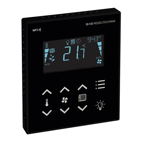
S+S Regeltechnik Rymaskon 200-Modbus Series User manual

S+S Regeltechnik
S+S Regeltechnik Rymaskon 600 User manual
S+S Regeltechnik
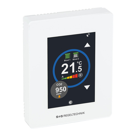
S+S Regeltechnik RYMASKON 700 Series User manual

S+S Regeltechnik
S+S Regeltechnik Rymaskon 200-Modbus Series User manual
S+S Regeltechnik
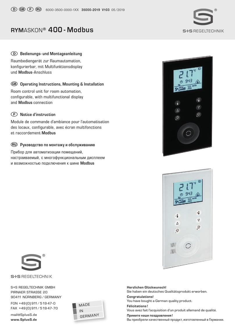
S+S Regeltechnik Rymakson 400-Modbus Repair manual

S+S Regeltechnik
S+S Regeltechnik THERMASREG FM Series Repair manual
