Diamatic BS-110 MKIII User manual

FOR MORE INFORMATION VISIT WWW.DIAMATICUSA.COM
Diamatic 05/2013 ● This document is not contractual ● Design and technical specifications may be subject to changes
OPERATING MANUAL BS-110 MKIII
VERSION 1.1

2
EC DECLARATION OF CONFORMITY
in accordance with Appendix II sub A of Directive 2006/42/EC
DIAMATIC USA
5220 Gaines Street
San Diego, CA 92110
Tel: 866.295.5512
Fax: 619.295.0754
Declare under our sole responsibility that the machine as described below conforms with the Health and Safety
requirements of the European Directive of the machine Safety.
In case of changes to the machine without our written authorization this declaration loses its validity.
Model: DIAMATIC BS-110-0135 MK III
BS-110-0235 MK III
Serial number: xxxxxB
1. satisfies the conditions set out in the Machine Directive (Directive 98/37/EC); Low voltage directive
(73/23/CEE, as last amended; EMC directive 89/336/CEE, as last amended)
2. satisfies the following harmonized standards:
EN 12100-1, EN 12100-2, EN60335-1 and EN55014-1
Nieuwegein 13-11-2013

3
Table of contents
EC Declaration of Conformity 02
1 Introduction 04
2 Machine description 04
3 Safety 06
Safety precautions
Safety regulations
Safety instructions
4 Initial operation 07
Checkpoints of electrical safety
Checkpoints of machine safety
Drive wheel engaging and disengaging
Transport wheel
5 Operation 08
Electric controls
Height adjusting steering handle
Narrow mode steering handle
Blade choice
Blade versions
Blade changing
Blade sharpening
Start up machine
Types of tear outs
Remove weights
6 Maintenance
Wheel scrapers 14
Replace shock absorbers
7 Technical data 15
Contact 16

4
1. Introduction
It is important that all persons who are working or maintaining this machine read the manual carefully and
understand it fully.
Keep this manual near to the machine, so it can always be consulted.
Only authorized and trained personnel may operate this machine.
2. Machine description
The Diamatic BS-110 stripper is ideally suited for small and medium sized applications. The machine have a
strong electric drive system with a very easy operating with forward, backward and speed control function.
Main assets of BS-110:
- Electrical driven machine with two electrical motors
- Forward and backward function.
- Standard speed control.
- User and environmentally friendly; very low noise level, easy to operate and low vibrations.
- Very high output
- Adjustable handle position.
- Shock absorbing handles.
- Wheel scrapers as standard.
- Small and compact equipment, so easy for transportation.
- Weights can easily removed.
- Heavy duty equipment, which is almost maintenance free.
- Standard transport wheel on machine.
- Lifting handle in front of machine and lifting eye in middle position of machine.
1
Tool holder
8
Mounting hole handle narrow position

5
2
M12 nuts, unscrew for remove weights
9
Drive switch lever for narrow mode
3
Transport wheel
10
Lifting eye
4
Selection switch
11
Drive wheel with quick release pin
5
Speed control
12
Hole for pin for handle in transport position
6
Clamp lever adjustable steer handle
7
Shock absorbing handle

6
3. Safety
It is important that all persons who are working with or maintaining this machine must read the manual
carefully and understand it fully.
Keep this manual always with the machine, to enable it to be referred to at any time.
Safety precautions
▪Make sure that persons who are not operating the machine are not in the surrounding area
▪The surface must be clear, avoid the risk of tripping.
▪Make sure that there are no cables or hoses in the driving direction of the machine.
▪Don’t get disturbed during the activities.
Safety regulations
▪Don’t change anything on the machine. Always use cables which are approved and safety earthed,
including extension cables. The machine is always equipped with an earthed connection, do not change
this and use always earthed cables with an earthed plug.
▪Connect the main power supply cable to an installation with an earth leakage circuit breaker.
▪Inspect and test the electrical components regularly. The electrical components have to satisfy to the
requirements which apply to these components.
▪Always call a skilled electrician or your distributor when you have questions about the safety of the
electrical components.
▪Work on electrical equipment or operating materials may only be undertaken by a skilled electrician or
by trained persons under the guidance and supervision of a skilled electrician as well as in accordance
with the electrical engineering regulations.
▪Pull out the main plug during inspections and repairing on the machine.
The following sticker is placed on the machine.
Meanings of these symbols are:
▪Ear protection is obliged
▪Safety glasses with lateral protection are obliged
▪CE-mark on this machine
▪Safety shoes obliged
▪Consult the manual before operating the machine
Personnel must tie back long hair and not wear loose clothing or jewellery including rings.
Wear gloves and dust mask during operating the machine.
Safety instructions
▪Pull out the main plug during inspections and repairing on the machine.
▪Keep the machine original, only use original Diamatic parts.
▪Do not pull out the power supply cable by the wire, but by the connector.

7
▪The weight of the BS-110 MKIII is 170kg with the weights. Use preferably appropriate appliances as a
lift or crane. Use the existing lifting points to lift the machine.
▪Never lift the machine with mounted tool! This sharp tool can be very dangerous!
4. Initial operation
Before using the machine it is of great importance to inspect the machine every day.
It is not permitted to use the machine if the machine safety is not according the checkpoints below.
Checkpoints of electrical safety
▪Use only extension cables for extending the main cable that are sized and marked in accordance with
the overall power consumption of the machine.
▪Electrical cables must be rolled entirely off of the reels.
▪Any damage to electric cables is not permitted.
▪Use an electrical power supply connection with earth connection.
Checkpoints of machine safety
Check if:
▪The safety functions and operating functions work correct.
▪There are not any loose nuts or bolts.
▪There are no damages on the electrical components.
Drive wheel engaging and disengaging
The drive wheels are engaged with quick release pins. Remove
them for easy transport by hand. Line up wheel hub hole and
wheel hole to insert pin as following: Push the machine side wards
so, that the drive wheel lift up and rotate it to line up the holes.
Never load or unload machine on a ramp or incline when wheels
are in the disengage mode. Failure to do so could cause machine
runaway, damage to machine, damage to property or cause
serious injury.

8
Transport wheel
The transport wheel helps to move the machine easily and
eliminate damaging to the floor. Loosen the 2 rubber clamps and
rotate the handle forwards. Secure the handle by inserting 2
quick release pins.
5. Operation
Electric controls
The selection switch (1) is mount on top of
machine. Switch to 1 to activate the
frequency driver and the machine is ready to
drive with drive motor. The drive speed can
be adjust with the drive speed control (2).
The right switch lever (3) switch the drive
motor to forward and the left switch lever
(4) switch the drive motor to backward.
Switch the selection switch to 2 to activate
the vibration motor. Selection switch on zero
switch off all functions.

9
Height adjustment steering handle
Adjusting the height of the steering handle is possible by loosening the clamp levers (1) to find a comfortable
working position.
Narrow mode steering handle
To work as close as possible along the wall it is possible to remove the right handle grip. The handle grip (2)
can be screw into the opposite side of the handle. The internal switch (1) lever can be used to switch the drive
motor to forwards.

10
Blade choice
Proper blade size and placement, depending on material and sub-floor type,
affects performance.
- The harder a job comes up, for best results, use a smaller blade.
- Start with a narrow blade, then increase the blade size to optimize the cutting pass.
- Narrower blades work easier than wider blades.
- Narrower blades usually clean the floor better.
- Normally bevel on blade is up for concrete. Bevel down for wood or soft sub-floors.
Blade versions
Blade #1 (Part No. E09533) - 305 x 76 mm, thickness 1,5 mm
self-scoring blade, bevel up, carpet, soft (PVC, linoleum, rubber)
Blade #2 (Part No. E09510) - 152 x 76 mm, thickness 1,5 mm
tile or linoleum on wood floors, difficult surfaces (ceramic, hardwood, heavy tile, etc.)
Blade #3 (Part No. E09512) - 254 x 76 mm, thickness 1,5 mm
carpet, tile or resilient on wood & concrete floors
Blade #4 (Part No. E09502) - 254 x 76 mm, thickness 2,5 mm
carpet, tile, PVC, Vct, tough coatings, hardwood & cork
11
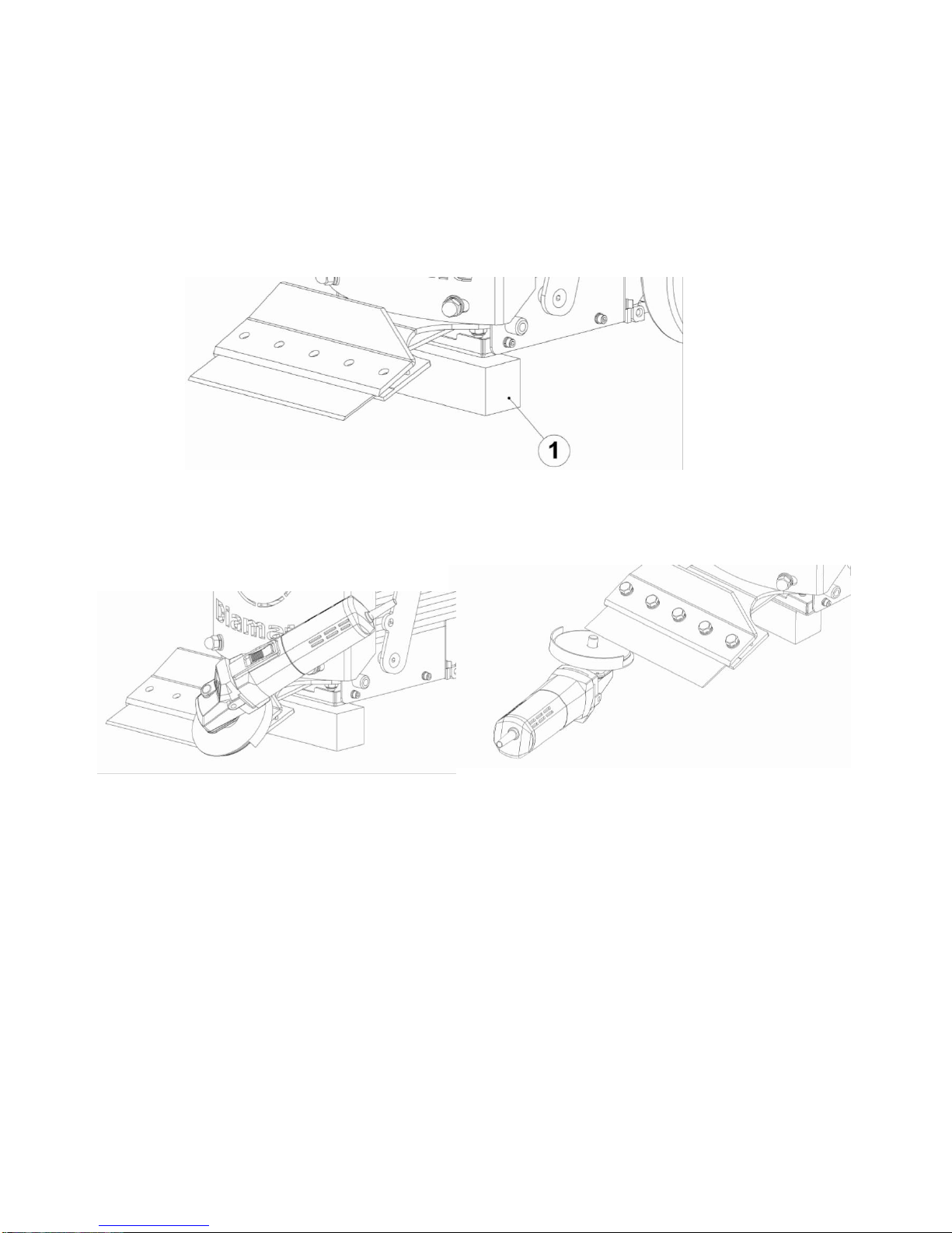
Blade changing
Dull blades greatly reduce cutting ability. Re-sharpen or replace as needed. Always wear gloves when changing
blades. Use extended wrench to keep hand safely away from the edge of the blade.
Place a bock (1) under the front of the machine and loose the five hex head bolts and replace the blade. It is
not necessary to remove the bolts. Be sure that the blade is far enough under the blade holder, to insure a
secure hold.
Blade sharpening
Always wear gloves and safety glasses. It is not necessary to remove the bolts. Sharpen the blade mounted to
the machine. Using hand grinder, block up front of machine so blade is off the floor. Sharpen the blade with a
10 cm diameter disk with 120 or finer grit. Be careful not catch disk on edge or corner of blade.
Blade bevel up Blade bevel down
Furthermore there is the opportunity to remove the blade from the machine and to sharpen the blade at a
vice, obeying the same way as shown in figures above.
Start up machine
The machine must be off before plugging the machine into power source.
1. Selection switch must be on ‘0’ position
2. Turn speed control to slowest position.
3. Plug in the main plug.
4. Turn the selection switch to ‘2’ position.
5. Engage forward or reserve switch.
6. Increase speed control to desired speed.
The frequency drive has been factory set, do not change any setting of the frequency drive.
Do not lock the wheel drive into a permanent position. If the operator would lose control or be disabled,
the machine continues to operate.

12
Types of tear outs
Keep blades sharp! Keep your work area clean and clear of debris.
Always wear eye- and ear- protection when working with the machine.
VCT - Tile
Never use a blade wider than the size of the tile being removed.
If goods being removed still do not come up clean or the machine jumps on top of goods, reduce blade size to
a smaller blade until proper blade size is found or use a smaller portion of the blade.
Vinyl-, Rubber, PVC, Direct glued carpet
Goods will need to be scored down to 254 to 305 mm for proper removal.
Pre-scored carpet makes machine easier to control and blades stay sharper longer. Blades up to 685 cm wide
can be used. Normally 305 mm blades are used on direct glued carpet, secondary backed, unitary, double
glued, vinyl foam, urethane foam. Latex foams come up easily with a 685 mm blade.
Self scoring blades can be used with some materials. A 254 mm blade is
recommended for this product, but determine what size blade
works best.
Ceramic (glued with double duty or mud sets):
Before removing ceramic tile, tiles will have to be pre-broke with a
mallet or large hammer. On small random block styles of tile, pre-breaking may not be necessary.
Open an area large enough for machine or blade to fit in, or start
from a doorway.
Keep work area clean to keep good wheel contact with floor. Use
slow speed and small blades.
Blades can be offset in cutting head for easier access
to toe kicks or removal along the wall.
Wood and wood like floors
Pound down or remove any nails or metal obstruction to avoid blade
damage.
Glued hard wood flooring
A 254 mm blade is recommended for regular adhesive, a 152 mm blade
for epoxy.
For proper removal of hardwood flooring (plank solid, plank laminated,
parkay, parquetry laminated)flooring must be scored to blade width.
This is done by using a circular saw set at a depth of 99% of the
thickness of the board, just missing the subfloor surface when on concrete
A chalk line for scoring lines can be used across the floor the width of
the blade
13
True parkay flooring scoring is not necessary. It will come up in small pieces.
When working over plywood sub-flooring, try to run machine in the same direction as
the grain in the wood. Blade in most cases bevel down. On solid wood floors like plank, run in the same
direction as the plank, not cross grain or cross plank. Removing the front counterweights will help on all soft
surfaces.
Concrete
When working on concrete slab, normal blade position is bevel up for best performance, especially when
cleaning adhesive. On occasion, bevel down gives better blade life.
Gibcrete and soft poured flooring
Usually require blade level down to create a better wearing surface, although bevel up may work if some
weights are removed.
Beware of expansion joints and floor mounted receptacles or other obstacles in the floor.
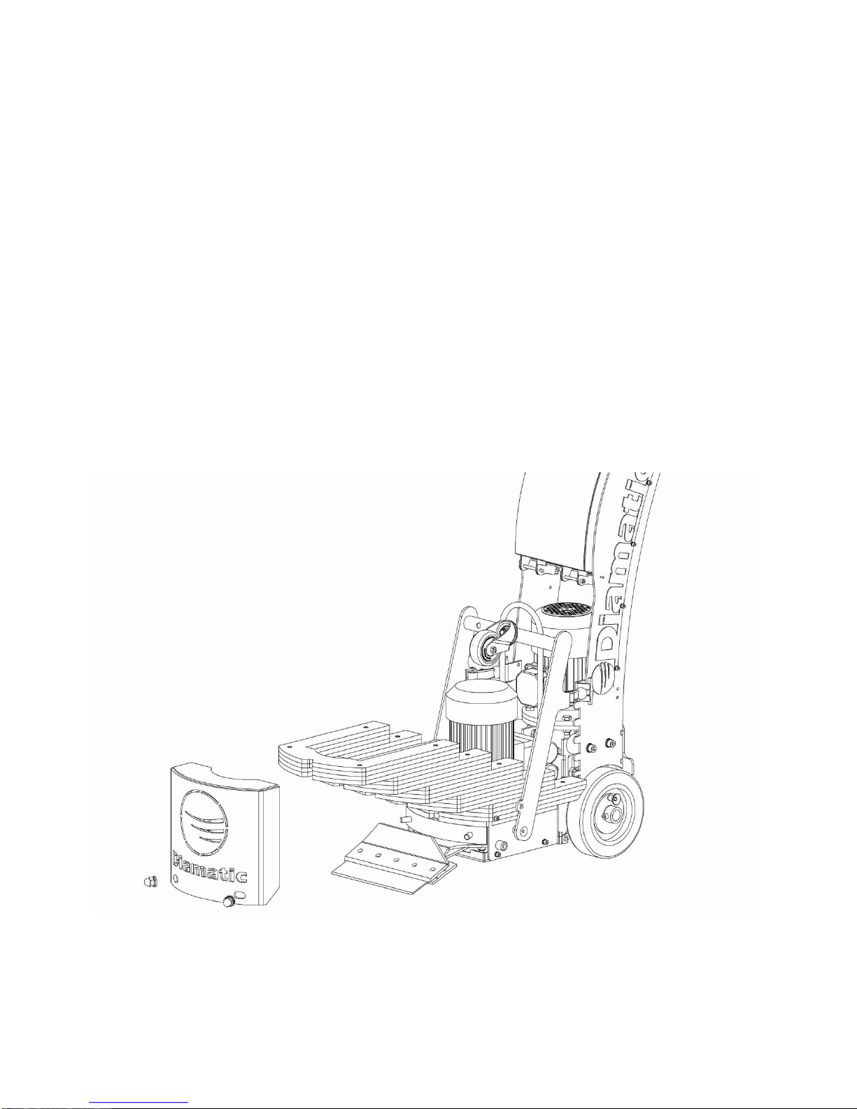
Remove weights
To remove weights, unscrew two M12 nuts at the front and remove the cover. Now it is possible to remove
weights by hand. By mounting the cover check if the cover is good positioned and if the two nuts are good
tightened.

14
6. Maintenance
Wheel scraper plates
Keep wheels clean from dirt/debris. To adjust the scraper plates unplug
electrical supply cable and loosen the bolts. Slide up to face wheel until it
touches but does not dig into the wheel surface.
Over tightening scraper plates could cause damage to wheel.
Replace shock absorbers
To replace the shock absorbers first remove the weights as described on
previous page. Unscrew the 6 bolts of the bottom cover, then remove bottom
cover. Unscrew the five M10 nuts of the cutting head and remove cutting
head. Remove the five big washers on shock absorbers. Unscrew the bolts of
the shock absorbers at top. Replace shock absorbers with the new ones and
apply Loctite on bolts to secure them. Put the five big washers on the shock absorbers. Carefully place the
cutting head on the shaft. Do not use hammer to prevent damage to the bearings. Tighten the five nuts of the
cutting head, mount the bottom cover and mount the weighs with the cover.

15
8. Technical data
BS-110 MKIII
Drive motor power
0.75 kW
Vibration motor power
0.75 kW
Drive speed Min. / Max.
Min. 2,4 m/min up to 18,5 m/min
Application
Hardwood parquet / ceramics / linoleum / vinyl / carpet /
adhesives / glue / tiles etc…
Length (L)
899 mm
Width (W)
522 mm
Height (H)
1062 mm
Minimum height steering
handle (H1)
888 mm
Maximum height steering
handle (H2)
1081 mm
Weight
170 kg
Design and specifications are subject to change without notice by Diamatic USA

16
DIAMATIC USA
5220 Gaines Street
San Diego, CA 92110
Tel: 866.295.5512
Fax: 619.295.0754
DIAMATIC MEXICO
-
-
-
-
-
DIAMATIC CANADA
-
-
-
-
-
Table of contents
Popular Power Tools manuals by other brands

EINHELL
EINHELL NEW GENERATION screwmaxx NGS 4.8 operating instructions

socomec
socomec DMS 400 Use - maintenance and spare parts

MULTIQUIP
MULTIQUIP Mikasa MVC-88VGE Operation and parts manual

Hitachi
Hitachi H 90SG Handling instructions

Dremel
Dremel 4200 Original instructions

Bosch
Bosch EasyDrill 12-2 Original instructions


