Priman PN-8820 Instruction Manual

Nitrogen Tyre Inflator Model: PN-8820
1
Vacuum Model Nitrogen Tyre
Inflation System Main Features:
■Pump the air from the tyre by the internal vacuum generator *
■Auto-Start Inflation *
■Single Tire Application
■Suit for: Motorcycle,Car, Light Truck
PN-8820 Nitrogen Tyre Inflator
Operation Steps
1.Set final target pressure using the + and - buttons. The upper LED
screen will show the target pressure.
2.Set the vacuum time using the + and - buttons. The lower LED screen
will show the vacuum time.
3.Lift the vehicle to avoid demage to the tyre due to the heavy vehicle
weight.
4.Remove the tyre valve core to exhaust the residual air from the tyre,
Then refit the tyre valve core.
5.Connect air hose to tyre valve stem.
6.Press"START"key.
7.When unit “beeps” and the upper LED screen flashes “END”, tyre
inflation is complete.
8.Immediately remove hose.

Nitrogen Tyre Inflator Model: PN-8820
2
1.0 Introduction
1.1 This Manual
Congratulation on selecting the tire Inflation Equipment.This equipment has a number
of unique features that are explained in this manual.
Throughout the manual the following symbols will be used, this information is for
your safety and to prevent damage to this product.
CAUTION
The hazard or unsafe practice could result in minor injury.
WARNING
The hazard or unsafe practice could result in severe injury or death.
1.2 General Specifications *
Hi-flow standard system suitable for serving passenger cars and LGV’s. This model
comes with an integral automatic purge and inflate cycle.
Technical data:
Power Requirement 110/240V/50-60HZ
Power Consumption 28W
Operating Temperature Range -20℃/-4℉to 70℃/158℉
Compressed Air Input Range 87-123PSI/6-8.5bar/600-850kPa
Nitrogen Purity 95-99.9%
Nitrogen Output 62L/min(2.2cfm)@131PSI/9bar/900kPa
Maximum Nitrogen Pressure 116PSI/8bar/800kPa
Nitrogen storage Tank 55L/14.5gal(US)
Dimensions(L*W*H) 720mm*570mm *1330mm/28.4”*22.4”*52.4”
Packing Size(L*W*H) 735mm*512mm*1455mm/28.9”*20.2”*57.3”
Net Weight 98kg/ 216.1 lbs
Gross Weight 114kg/251.3lbs
*Note: Specifications may vary for non-standard equipment. Contact service agent
for further information.
Nitrogen Tyre Inflator Model: PN-8820
3
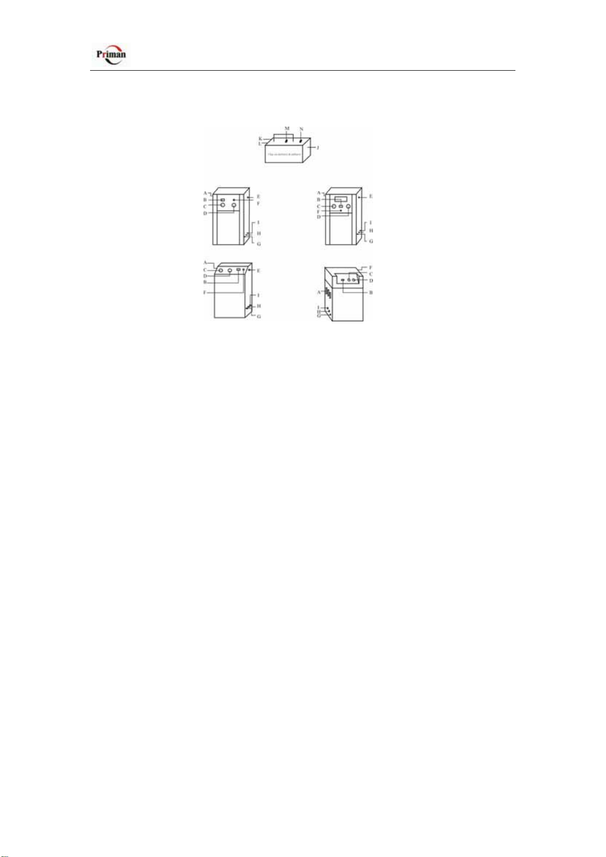
2.0 Control Layout
A: Inlet of compressed air and regulator
B: Hours run
C: System pressure gauge: Indicate the compressed air inlet pressure
D: Nitrogen pressure gauge
E: Power cable
F: Power switch
G: Automatic nitrogen inflation outlet
H: Compressed air outlet
I: Manual nitrogen inflation outlet
J: 0.7m hose: To the tire
K: Compressed Air inlet & Deflate ball valve
L: Nitrogen inlet & Inflate ball valve
M: Tire pressure gauge: Indicate the tire pressure when the Nitrogen inlet & Inflate
ball valve (L)
turn off
N: Inflate/Deflate control valve
3.0 Preparation for Use
1.Unpack the carton and identify the components.
Description Quantity
Unit 1
Hosewithsingleclip-onopentypechuck 1
Black Clip-on deflator&inflator—Supplied separately 1
Hosewith2quickcouplers—Suppliedseparately 2

Nitrogen Tyre Inflator Model: PN-8820
4
2. Connect the compressed Air supply to the Inlet of compressed air (A) located in the
regulator.
The inlet regulator should be set at 123PSI/8.5bar/850kPa
3. Connect the Hose with single clip-on open type chuck to AutomaticCnitrogen
inflation outlet (G) located in the unit
4. Connect the Manual nitrogen inflation outlet (I) located in the unit and the Nitrogen
inlet & Inflate ball valve (L) located in the Black Clip-on deflator&inflator by a Hose
with2quickcouplers.
5. Connect the Compressed air outlet (H) located in the unit and the Compressed Air
inlet & Deflation ball valve (K) located in the Black Clip-on deflator&inflator by
another Hose with 2 quick couplers.
6. Turn off the Deflation ball valve (K) and the Inflation ball valve (L).
7. Turn on the Compressed air outlet (H), the Automatic nitrogen inflation outlet (G)
and the Manual nitrogen inflation outlet (I).
8. Connect the power supply.
9. Press the power switch (F) to turn on the unit.The machine will produce the
nitrogen. The Nitrogen Pressure gauge (D) located in the machine will indicate the
Nitrogen Pressure in the internal Nitrogen Storage Tank.
10.Check that the Nitrogen Pressure in the internal Nitrogen Storage Tank is higher
than 72psi/5.0bar/500kPa. The equipment is now ready to use.
CAUTION
To avoid equipment damage. The compressed Air supply must be filtered by filter
(5micron) supplied separately which is to filter the oil and water in the compressed
air.
To avoid equipment damage, never exceed the maximum inlet pressure.
The filter bowls will accumulate water and oil when the machine is in operation and
require regular emptying by means of a manual drain at the base of the bowl (Turn
anti-clockwise to open and clockwise to close).
It is important that the filter elements are replaced on a regular basis to prevent water
and oil entering the machine.

Nitrogen Tyre Inflator Model: PN-8820
5
4.0 Operation
4.1 Manual inflation by the Black Clip-on deflator&inflator
To increase the purity of the nitrogen in the tire the air must be removed.
4.1.1 Air extraction
1. Connect 0.7m hose (J) to the tire.
2. Turn the Inflation/Deflation control valve (N) handle to “Air extraction” position.
3. Turn on the Deflation ball valve (K).
4.1.2 Nitrogen inflation
1. Turn the Inflation/Deflation control valve (N) handle to “N2 Inflation” position.
2. Turn on the Inflation ball valve (L).
3. Tire pressure gauge will indicate the tire pressure when the Nitrogen inlet &
Inflation ball valve (L) turn off
CAUTION
If the tyre is still in position on the vehicle, it is paramount that all weight be taken off
the tyre by means of jacking the car up before deflating the tyre. The tyre must remain
without load until re inflation is complete.
4.2 Automatic Inflation
4.2.1 Topping Up of Nitrogen
1. A choice between bar, PSI, Kgf/cm2 and Mpa on the keypad is available by
pressing the white ‘C arrow key’before preferred choice.
2. Press the tyre pressure keys ‘∇’ or ‘∆’to set the final inflation pressure required.
3. Connect the hose to Tire, ensure the hose is connected securely. Nitrogen leaks will
cause a error message to be displayed.
4. If the pressure in the tire is higher than 15 psi, 100 kPa or 1.0 bar, the process will
commence.
5. When the top up cycle is completed, the unit beeps and the target pressure flashes
in the display.

Nitrogen Tyre Inflator Model: PN-8820
6
4.2.2 Nitrogen Filling of the New Tire
1. A choice between bar, PSI, Kgf/cm2 and Mpa on the keypad is available by
pressing the white ‘C arrow key’before preferred choice.
2. Press the time setting key ‘∇’ or ‘∆’ for purge/vacuum cycle. The default value of
the machine is 20 seconds and the user can increase or decrease this setting according
to the tyre size.
3.Press the tyre pressure keys ‘∇’ or ‘∆’to set the final inflation pressure required.
4. Connect the hose to Tire, ensure the hose is connected securely. Nitrogen leaks will
cause a error message to be displayed.
5. Press the key ‘START’ for automatic purging cycle and nitrogen inflation to
commence.
6. When the top up cycle is completed, the unit beeps and the target pressure flashes
in the display.
4.2.3 To Convert Existing Mounted Air-Filled Tire to Nitrogen.
1. If the tyre is still in position on the vehicle, it is paramount that all weight be taken
off the tyre by means of jacking the car up before deflating the tyre. The tyre must
remain without load until re inflation is complete.
2. Deflate the tyre by removing the valve stem and once deflated, re-insert.
3. A choice between bar, PSI, Kgf/cm2 and Mpa on the keypad is available by
pressing the white ‘C arrow key’before preferred choice.
4. Press the time setting key ‘∇’ or ‘∆’ for purge/vacuum cycle. The default value of
the machine is 20 seconds and the user can increase or decrease this setting according
to the tyre size.
5. Press the tyre pressure keys ‘∇’ or ‘∆’to set the final inflation pressure required.
6.Connect the hose to Tire, ensure the hose is connected securely. Air leaks will cause
a error message to be displayed.
7. Press the key ‘START’ for automatic purging cycle and nitrogen inflation to
commence.
8. When the top up cycle is completed, the unit beeps and the target pressure flashes
in the display.
CAUTION
Should the inflation line detach from the valve during inflation the machine will
display the code ‘Err’.
Pressing the key ‘pause’at any time will stop the operation and repressing ‘pause’ will
start the operation.

Nitrogen Tyre Inflator Model: PN-8820
7
5.0 The Pressure Calibration Procedures
To the automatic tyre nitrogen inflators, when the users found the inflator accuracy is
higher than 1.5PSI / 0.1bar / 0.01Mpa / 0.1Kgf/cm2, they can calibrate the unit by the
following methods.
1. Open the tyre nitrogen inflator,the below part is seeing on the top of the machine.
2. Turn off the power, take off the accessory (C) from the kick 4 and kick 5 of the
accessory (B), then insert it to the kick 1 and kick 2 of accessory (A).Turn on the
power.
3. Find a 14 inch tyre with the pressure inflated to 2.5bar/36PSI exactly,connect the
tyre to the Automatic nitrogen inflation outlet (refer to Section 2.0 Cntrol Layout)
located in the nitrogen inflator by the Hose with single clip-on open type chuck
inclouded (the customer also should use this hose to inflate tyres,or else will cause
measuring difference.)
4. Currently,the tyre nitrogen inflator LED (PRESSURE SETTING) will display the
pressure reading value,maybe 2.3 bar,2.4 bar,2.5 bar,2.6 bar or other values.Rotate the
knob on the accessory (D) with screwdriver, the reading on the LED will
changing,and adjust the LED display pressure into 2.4 bar/35PSI.
5. Deflate the tyre totally,and the tyre pressure should be 0 bar at this moment,then
connect the tyre to the the Automatic nitrogen inflation outlet (refer to Section 2.0
Cntrol Layout) located in the nitrogen tire inflator (or disconnect the tyre from the
nitrogen tire inflator,and let the Automatic nitrogen inflation outlet located in the
nitrogen tire inflator linked to the atmosphere.)
6. Now the LED will display 0.01 bar,0.02 bar,0.03 bar or any other digitals,then
rotate the knob on the accessory (E) with screwdriver.The reading on the LED will
change too,and adjust the LED display pressure into 0.01 bar.

Nitrogen Tyre Inflator Model: PN-8820
8
7. Repeat the steps 3,4,5,6 three times.
8.Turn off the power,take off the accessory (C) from the kick 1 and kick 2 of the
accessory (A),then insert it to the kick 4 and kick 5 of accessory (B).Turn on the
power again.
9 .The calibration is over.
Producer: ZHUHAI PRIMAN AUTO MAINTENANCE EQUIPMENT CO.,LTD
ADD: 2# PLANT, MINGHONG INDUSTRY BASE, LIANGANG INDUSTRIAL
ZONE ZHUHAI CITY, GUANGDONG PROVINCE P.R. CHINA
TEL:86-756-7799055
FAX:86-756-6210996
EMAIL:zhpriman@zhpriman.com
MSN: zhpriman@hotmail.com
Skype: zhpriman
Website: http://www.zhpriman.com
Table of contents
Other Priman Power Tools manuals

Popular Power Tools manuals by other brands

SUHNER
SUHNER ABRASIVE UMB 4-RQ Technical document

EINHELL ERGO TOOLS
EINHELL ERGO TOOLS E-ASS 4,8V operating instructions

Hilti
Hilti NURON SMT 6-22 Original operating instructions

Bosch
Bosch GST 650 Professional Original instructions

spectratime
spectratime iSource Plus StarLPRO-1500 manual

Florida Pneumatic
Florida Pneumatic FP 747 operating instructions


Thermopatch
Thermopatch HS-4-C manual

Grizzly
Grizzly AGS 360 Lion Translation of the original instructions for use

Schmidt
Schmidt HydroPneumaticPress Translation of the original assembly instruction

STEINEL
STEINEL HG 5000 E Information

ATI Technologies
ATI Technologies Flexdeburr RC-1000 Series product manual

Metabo
Metabo W 2200-230 Original instructions