manuals.online logo
Brands
  1. Home
  2. •
  3. Brands
  4. •
  5. Diamond Antenna
  6. •
  7. Antenna
  8. •
  9. Diamond Antenna X500HNA User manual

Diamond Antenna X500HNA User manual

XSOOHNA
2M/70CM
DUAL
BAND
HIGH
PERFORMANCE
GAIN
VERTICAL
ANTENNA
DIRECT
JOINT
SYSTEM
FRP
OUTERSHELL
LINER
PHASE
SHIFTER
SYSTEM
OPERATION
INSTRUCTIONS
DIAMOND
ANTENNA
®@
Description
Newly
developed
Linear
Phase
Shift
technology
and
Direct
Joint
structure
by
three-piece
FRP
outershell
enable
to
achieve
the
following
performance.
1)2m
5/8
wave
three-element
C-Load
and
70cm
5/8
wave
eight-element
strucutre.
2)High
performance
and
high
maximum
power
rating
at
2m
and
70cm
bands.
3)Low
vswr
and
broader
coverage
at
2m
and
70cm
bands.
4)Overlapping
three-piece
FRP
outershell
structure
is
strong
enough
to
compete
with
one
piece
structure.
5)Ring
gasket
provides
perfect
waterproof.
6)Ideally
tapered
FRP
outershell
has
enough
thickness
to
withstand
strong
wind
and
avoid
unwanted
QSB.
7)Joint
bracket
can
be
fastened
securely
by
special
wrench
attached.
8)DC
ground
structure
of
the
antenna
protects
transceiver
from
high
voltage
caused
by
thunder
lightning.
9)Feedpoint
connector
is
being
exposed
downward
at
the
bottom
of
support
pipe
to
make
antenna
installation
or
detachment
easier.
10)With
optional
2m/70cm
duplexer,
two
bands
can
be
transmitted
simultaneously,
or
one
band
can
be
transmitted
simultaneously
while
receiving
the
other
band.
@
Assembly
Note
;
Be
sure
to
assemble
from
upper
element.
If
the
antenna
is
being
assembled
from
lower
element,
element
can
not
be
pulled
out
from
outer
shell
and
fastened
properly.
1)Put
special
wrenches
on
upper
and
center
FRP
outershells
as
shown
in
the
Fig.
1.
Use
small
diameter
section
of
the
wrench.
Upper
FRP
outershell
Center
FRP
outershell
Special
wrench
Fig.
1
2)Connect
upper
element
in
the
upper
FRP
outershell
and
center
element
in
the
center
FRP
outershell
with
screwdriver.
Upper
element
Upper
FRP.
element
outershell
Center
FRP
Center
outershell
Screw
driver
Fig.
2
3)After
connecting
these
two
elements
in
the
outershells,
fasten
upper
FRP
outershell
joint
bracket
with
special
wrenches
as
shown
in
the
Fig.
3.
Fasten
the
bracket
thoroughly
until
there
is
no
gap
between
each
part
of
the
bracket.
4)
After
fastening
the
bracket,
detach
the
wrenches
from
the
outershells
as
shown
in
the
Fig.
4.
5)Connect
center
element
in
the
center
FRP
outershell
and
lower
element
in
the
lower
FRP
outershell
the
same
way
as
section
2,3
but
use
larger
diameter
section
of
the
wrenches
at
this
time
as
shown
in
the
Fig.
5.
Lower
FRP
Lower
Center
Center
FRP
outershell
element element
outershell
Larger
diameter-
Larger
diameter
section
of
section
of
the
wrench
:
the
wrench
Screw
driver
Fig.
5
6)Attach
three
radial
elements
with
the
wrench
as
shown
in
the
Fig.
6.
7)Attach
mast
brackets
on
support
pipe
and
fix
them.
8)Attach
assembled
antenna
on
mast
as
shown
in
the
Fig.
8.
In
installing
the
antenna
be
sure
to
take
whole
balance
into
account.
Mast
SS
bracket
Mast
Mast
|
bracket
Zw
Fig.
7
9)Then
connect
coaxial
cable
with
N
connector
to
feedpoint
section
at
the
bottom
of
the
antenna
through
waterproof
sleeve
as
shown
in
the
Fig.
9.
10)After
connecting
coaxial
cable,
fix
waterproof
sleeve
to
the
bottom
of
support
pipe
with
a
screw.
Turn
connected
coaxial
cable
once
to
make
a
loop
at
right
below
the
antenna
as
shown
in
the
Fig.
10
to
escape
excess
load
from
the
cable.
Mast
|
Support
|
pipe
Mast
Support
pipe
Waterproof
sleeve
Coaxial
cable
—
=A
Make
a
loop
6
Fig.
9
Fig.
10
@
Adjustment
The
X500HNA
antenna
is
completely
adjustment
free.
If
vswr
of
the
antenna
is
extraordinary
high,
most
likely,
it
is
due
to
coaxial
cable
and
connector
contact,
or
connector
soldering
problem.
And
be
sure
to
use
502
coaxial
cable
to
feed
the
antenna.
@
Note;
Though
the
X500HNA
is
DC
ground
structure,
circuit
across
the
inner
conductor
and
outer
conductor
is
open-
circuit
when
measured
by
a
volt-ohm
meter.
If
it
is
close-circuit,
confirm
coaxial
cable
connections
well.
Use
the
antenna
vertically.
If
the
antenna
is
tilted,
it
can
not
perform
perfectly
as
it
is
expected.
@
VSWR
2m
oc
Sata
Seay
aes
4KHrwrRanim®HL\.
a=
T
144MHz
146MHz
148MHz
70cm
435MHz
440MHz
445MHz
450MHz
®
Specifications
Frequency
:
144—148MHz,
435—450MHz
Gain
:
8.3dB(2m),
11.7dB(70cm)
Impedance
:
50ohms
VSWR
:
Less
than
1.5:1
Max.
power
rating
:
200W
Max.
wind
resistance
:
40m/sec(90MPH)
Mast
diameter
accepted
:
30—60mm(1
1/5”
to
2
2/5”)
Length
:
5.4m(212.6”)
Radial
length
‘
approx.
52cm(20.5”)
Weight
:
2.6kg(5.731bs.)
Connector
:
N
Type
:
5/8
wave
three-element
C-Load
antenna(2m)
5/8
wave
eight-element
C-Load
antenna(70cm)
@®
Part
name
Upper
FRP
outershell
with
upper
element
and
gasket
holder
(A)
Outershell
joint
bracket
(A)
Gasket
holder
(A)
Gasket
(A)
Center
FRP
outershell
with
center
element
and
outershell
joint
braket
(B)
|
and
gasket
holder
(B)
Outershell
joint
bracket
(B)
Gasket
holder
(B)
Gasket
(B)
Lower
FRP
outershell
with
lower
element
and
impedance
matching
section
:
H
Radial
ie
Radial
element
holder
Mast
bracket
with
lock
screw
Waterproof
sleeve
FOR
YOUR
SAFETY
Read
the
following
safety
precautions
before
start
assembling
the
antenna.
eAssemble
the
antenna
on
the
ground
or
wide
and
flat
place
such
as
on
balcony
before
installation.
eDo
not
assemble
or
install
the
antenna
on
a
place
where
you
can
not
have
enough
distance
from
any
electric
power
lines.
eDo
not
install
the
antenna
on
a
rainy
or
windy
day.
eDo
not
attempt
to
install
the
antenna
only
by
yourself.
Installing
the
antenna
alone
onthe
roof
may
lead
you
dangerous
accident.
Always
ask
your
friends
for
help
installing
the
antenna.
eDo
not
use
iron
or
aluminum
ladder
at
areachable
distance
from
any
electric
power
lines.
eDo
not
install
the
antenna
on
a
mast
which
is
not
grounded
.
properly.
eDo
not
have
your
family
members
or
friends
touch
or
come
close
to
the
antenna,
unless
they
have
realized
its
potential
danger.
TO
AVOID
FATAL
ACCIDENT
eDo
not
attempt
to
sustain
the
antenna,
or
any
part
of
support
structure
if
it
begins
to
fall
down.
Let
it
fall
by
itself.
Do
not
attempt
to
remove
or
restore
the
antenna
or
any
part
of
support
structure
if
it
touches
a
electric
power
line
by
chance.
Let
it
be
as
it
is,
do
not
touch
it,
and
call
your
local
electric
power
company
immediately.
IN
CASE
OF
AN
ACCIDENT
eDo
not
touch
a
person
or
an
animal
who
is
or
seems
to
be
in
contact
with
the
antenna
or
any
support
structure
which
is
fallen
on
alive
eletric
power
line.
Touching
one
may
lead
you
to
be
electrocuted.
eDo
not
attempt
to
separate
a
person
or
an
animal
who
is
or
seems
to
be
in
contact
with
the
antenna
or
any
support
structure
which
is
fallen
on
a
live
electric
power
line
by
yourself.
Call
or
have
someone
call
a
police
officer,
ambulance,
doctor
immediately.
You
con
be
If
thls
product
comes
neor
electric
power
Ines
READ
INSTRUCTIONS
ANTENNA
INSTALLATION
PRECAUTIONS
To
determine
antenna
installation
location,
there
are
several
factors
to
be
taken
into
account.
First
thing
is
antenna
propagation
direction
to
specific
target
stations.
As
to
whether
there
is
any
obstacles
such
as
tall
buildings
on
the
line
of
sight.
Next
is
specific
installation
location.
As
to
whether
specific
location
is
adequate
in
terms
of
antenna
support
and
sur-
rounding
safety.
Minimum
distance
to
power
lines
Twice
the
length
of
antenna
assembly
eDo
not
attempt
to
install
the
antenna
by
yourself
if
you
do
not
have
any
experience
in
installing
base
station
antenna.
Ask
your
experienced
friends
or
professional
for
help.
eDo
not
attemptto
install
the
antenna
at
alocation
where
does
not
have
enough
distance
from
nearby
electric
power
lines.
It
is
advised
to
install
the
antenna
at
least
twice
of
total
antenna
height
from
nearby
electric
power
lines.
eDo
not
install
the
antenna
on
any
type
of
tower,
pole
or
telescopic
mast
which
exceeds
30
feet
high,
if
you
do
not
have
enough
experience
in
installing
the
antenna
on
that
kind
of
location.
Ask
your
experienced
friends
or
professional
for
help.
eDo
not
use
more
than
1/10'sectionif
you
install
the
antenna
on
iron
plumber’s
pipe.
Attach
guy
wire
if
multiple
pipes
are
used
to
install
the
antenna.
—_
-
nme
f
--
|
a
it
+
.
/
o2004
-
+
:
NIBHAU
J)
SS".
:
Pi
f
’
/
&»>
|
:
1™
ze
:
‘
f
+
Jit
4
ere
:
eonn
Ve
s
4
Y
«<
;
slisteni
is
aenirmelsb
of
)
af
oO!
divs!
yf
h
6b
NOUR
DSQUIg
Yonis
20
gtz
j2
adlngiadd
yne'
ae
orert
Nasco!
noiisilsteni
sitteage
2
txelVl
S
in
2
i
ofsupebs
2
Olle2ol
Vielbe
omonuc
W
TU
'
—
-
~——
mond
”
—
:
a
T
a
ae
—|
ie
.
:
>
at
_
rs
<~
\
”
'
a“
S
4
=
“
<
<>
Ul
oe
——
™
“
:
“
=
t
j
7
"
_a
>
—_—
a
i-
lezluoy
vd
eoneing.es!t
isiznt
of
james
ton
oe
s1ns
i6l2.
625
MUuUNGI2S
|
s1SNSOxS
YN
evel
qlort
ot
lsnolzesiova
10
ebnesitt
besnenegxe
woy
.
“
,
ry
.
wer
;
JO
¢
ii
anvils
efi
inieth
Gites
rn
Gue
2WOr
Hoels
ydisen
mot
sdnci2ib
ripuone
oven
fon
“tat
to
aiv
sel
ts
annatins
aril
isteni
of
besivbs
2)
ff
nov
fipied
snosing
vewo!
to
say!
ys
no
Bnceins
ett
fiefeni
jon
oGe
“
t2gmM
digopasiol
eff
no
sonsins-edlt
pniisieni
of
eoasieaxe
‘tpvons
even
nelagxes
woy
w#eA
noisoel
fo
Sant
glen
jal
Isnotezstaig
voy
inoifase"0l\T
nacdi
sven
seu
fon
ode
avs
239qiq
elaitium
bh
euw
yup
doatA
jegiqg
e
edmiig
noWne
oneings
of
lisient
o)
beau
Ory
mun
igaei
OF
suseanxe
fz
DIAMOND
ANTENNA
CORPO
TION
‘"
15-1,
|-chome,
Sugamo
Toshima-ku,
Tokyo
170,
eoet
Phone:(03)947-1411!
Telex
120
DIA’
oA
aw
sioted
enoliusse1q
yielse
gaiw
:
6hneine
ad
ae!q
Jett
bns
ebiw
10
beweng
edf
nes
noise
ated
uGyY
@yer
we
aoe
ig
8
nO
Snn
Ss
Aer
Reterd
zon!
vewog
cusses
yne
nothgonetel
ig
ysh
yoniw
10
yntel
eno
snot
Jiezwoy
¥d
Wino
BAhelne
edt
fisteniat
soy
beel
yom
toonenfAe
encieusnae
qian
19t
2bnen!
~woy
es
ayswik
sonéiziy
sidsdage).s
Is
Tebbs!
runt
esr
;
bebnuclp
ian
ef
Noltiw
igsri
&
no
sit
a
ae
mao
10
fSvo)
zhaeittio
eadment
ims?
wo
isifroiog
ah
besilse
over
yer!
2esinu
6m
THSQIDDA
IAT
Hoaqua
jo
neg
uné
10
,snineins
erie
loefi
vd
lis?
fi
jat
unwob
Neg
yns
10
enqoing
ed)
erates)
io
4y0
vd
erwi
Yewor
onivele
&
2ersuol
i
fou
af
wey
testis
Taian
bal
Go
a
THQIDOA
MA
30
3
ad
of
emeseto
aborwieming
—
ai
foi
owiouile
Noegque
yius
10
Seneins
ell
riiw
teh
uny
bsel
yam
ateehtis
+
Oni
role
ei
pn
1
¥
?
@
Ag
ane
fo
are
br?
can
>
ct
ah
mea
TO
2
orfw
Isming
ns
h6eque
yns
sonoiins
«
er

Other Diamond Antenna Antenna manuals

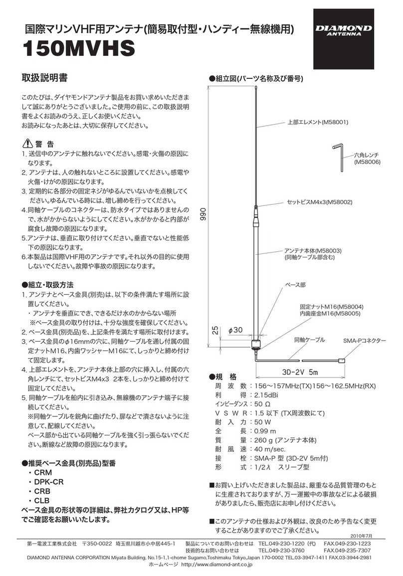
Diamond Antenna 150MVHS User manual

Diamond Antenna

Diamond Antenna 150MVHS User manual

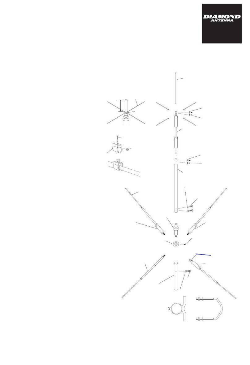
Diamond Antenna K400 User manual

Diamond Antenna

Diamond Antenna K400 User manual

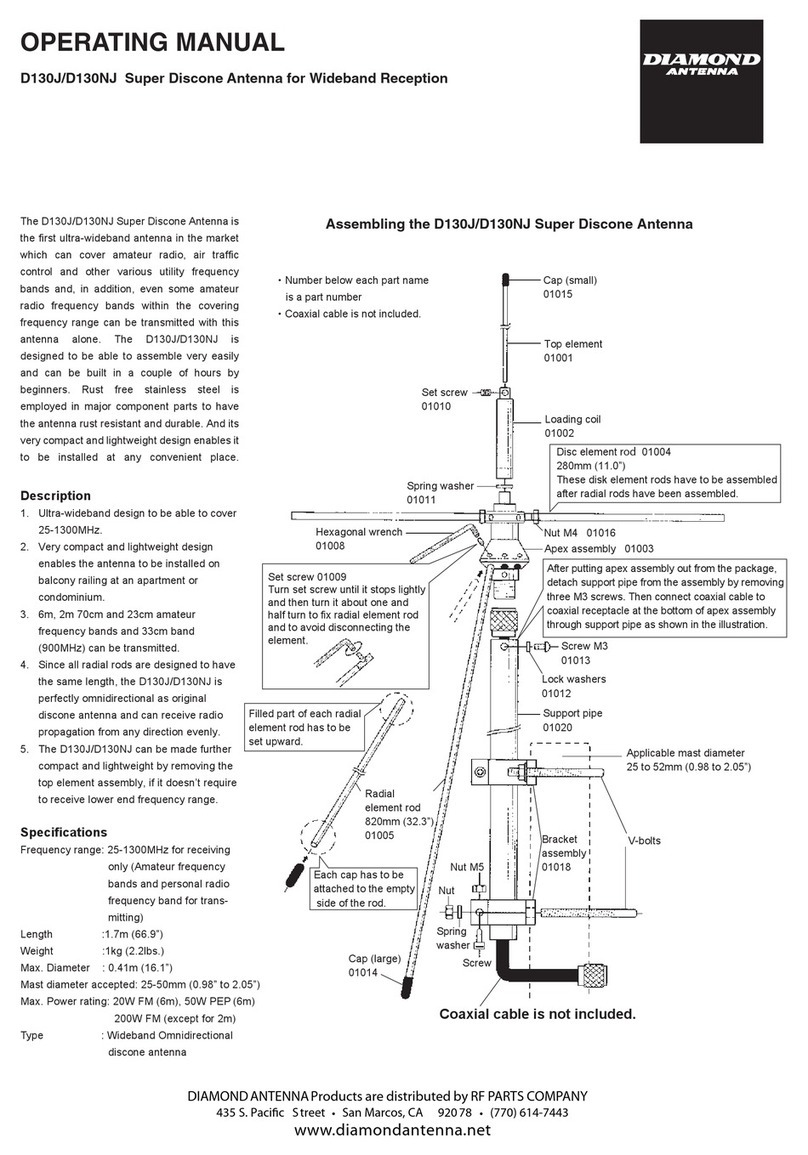
Diamond Antenna WD330S User manual

Diamond Antenna

Diamond Antenna WD330S User manual

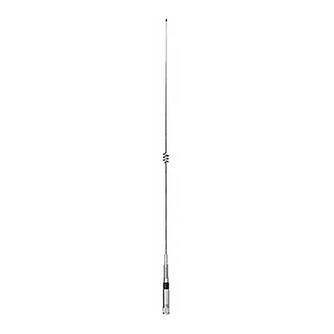
Diamond Antenna CR-10H User manual

Diamond Antenna

Diamond Antenna CR-10H User manual

Diamond Antenna HV7A User manual

Diamond Antenna

Diamond Antenna HV7A User manual

Diamond Antenna KV5 User manual

Diamond Antenna

Diamond Antenna KV5 User manual

Diamond Antenna CP-6S User manual

Diamond Antenna

Diamond Antenna CP-6S User manual

Diamond Antenna HF6CL User manual

Diamond Antenna

Diamond Antenna HF6CL User manual

Diamond Antenna A430S10 User manual

Diamond Antenna

Diamond Antenna A430S10 User manual

Diamond Antenna HFV8040 User manual

Diamond Antenna

Diamond Antenna HFV8040 User manual

Diamond Antenna W-735 Technical manual

Diamond Antenna

Diamond Antenna W-735 Technical manual

Diamond Antenna CP-725H User manual

Diamond Antenna

Diamond Antenna CP-725H User manual

Diamond Antenna A144-S5 User manual

Diamond Antenna

Diamond Antenna A144-S5 User manual

Diamond Antenna BB2M User manual

Diamond Antenna

Diamond Antenna BB2M User manual

Diamond Antenna A144-S5 User manual

Diamond Antenna

Diamond Antenna A144-S5 User manual

Diamond Antenna MV3A User manual

Diamond Antenna

Diamond Antenna MV3A User manual

Diamond Antenna BB7V User manual

Diamond Antenna

Diamond Antenna BB7V User manual

Diamond Antenna SG-M510 User manual

Diamond Antenna

Diamond Antenna SG-M510 User manual

Diamond Antenna CPVU8 User manual

Diamond Antenna

Diamond Antenna CPVU8 User manual

Diamond Antenna BB6W User manual

Diamond Antenna

Diamond Antenna BB6W User manual

Diamond Antenna V2000A User manual

Diamond Antenna

Diamond Antenna V2000A User manual
Diamond Antenna CR8900A User manual

Diamond Antenna

Diamond Antenna CR8900A User manual

Diamond Antenna A430S10 User manual

Diamond Antenna

Diamond Antenna A430S10 User manual

Diamond Antenna SG-M911 User manual

Diamond Antenna

Diamond Antenna SG-M911 User manual

Popular Antenna manuals by other brands

NetComm Wireless NRB-51 user guide

NetComm Wireless

NetComm Wireless NRB-51 user guide

1 BY ONE 203NA-0001 user manual

1 BY ONE

1 BY ONE 203NA-0001 user manual

Self-Sat SNIPE MOBIL CAMP DIRECT user manual

Self-Sat

Self-Sat SNIPE MOBIL CAMP DIRECT user manual

Self-Sat MAM03D Installation guidelines

Self-Sat

Self-Sat MAM03D Installation guidelines

Self-Sat SNIPE 3 user manual

Self-Sat

Self-Sat SNIPE 3 user manual

Remo+ BAS-2003 LTE MiMo Indoor Quick user guide

Remo+

Remo+ BAS-2003 LTE MiMo Indoor Quick user guide

1 BY ONE 202EU-0007 Instructional manual

1 BY ONE

1 BY ONE 202EU-0007 Instructional manual

Self-Sat H50D Series user manual

Self-Sat

Self-Sat H50D Series user manual

COMBA COMFLEX Series user manual

COMBA

COMBA COMFLEX Series user manual

Raven 122 1.2 Meter Assembly instructions

Raven

Raven 122 1.2 Meter Assembly instructions

Audio Technica ATW-A62P Installation and operation

Audio Technica

Audio Technica ATW-A62P Installation and operation

M2 Antenna Systems 450-800-12 Assembly manual

M2 Antenna Systems

M2 Antenna Systems 450-800-12 Assembly manual

AMX NXA-WAP2413A Specifications

AMX

AMX NXA-WAP2413A Specifications

Audio Technica ATW-A49 Installation and operation

Audio Technica

Audio Technica ATW-A49 Installation and operation

Channel Master CM-3000A instruction sheet

Channel Master

Channel Master CM-3000A instruction sheet

Megasat Caravanman Kompakt user manual

Megasat

Megasat Caravanman Kompakt user manual

Wideye FX 500 user manual

Wideye

Wideye FX 500 user manual

Palstar AA30 owner's manual

Palstar

Palstar AA30 owner's manual

manuals.online logo
manuals.online logoBrands
  • About & Mission
  • Contact us
  • Privacy Policy
  • Terms and Conditions

Copyright 2025 Manuals.Online. All Rights Reserved.