Diamond Audio Technology D5 300.4 User manual

LIMITED WARRANTY STATEMENT
Diamond Audio Technology, Inc. (DAT) warrants all DAT products to be
free of defects in material and workmanship for a period of one (1)
year from the date of original purchase provided they are purchased
from an authorized DAT retailer in the United States. However, the
effective warranty period will be three (3) years if the products were
purchased from and installed by an authorized DAT retailer.
What is covered: Parts and labor to effect repair or, at the sole
discretion of DAT, replacement of either any malfunctioning or
defective part(s) or the entire system should the system or any
component part(s) thereof fail to perform as designed. Includes return
freight via ground transportation to destinations within the United
States.
What is NOT covered: Installation or setup and repair or replacement of
the system or any parts thereof which, in DAT’s judgment, fail or
become damaged as a result of negligence, improper use, abuse,
unauthorized modification or service, improper or inadequate
packaging during shipment, installation by a non-authorized dealer,
accident, or use for any purpose other than those for which this
product was originally intended, or where the model’s serial number
has been removed, altered or defaced.
Who is covered: Original purchaser so long as they reside in the United
States and can provide proof of the original date of purchase (e.g.,
store receipt) from an authorized DAT retailer.
OUTSIDE THE UNITED STATES: Customers outside the United States
should contact their local sales office to obtain information on prices,
exchange unit availability, instructions, service and warranty/non-
warranty repairs.
Repair or replacement under this warranty is the exclusive remedy of
the consumer. DAT shall not be liable for any incidental or
consequential damages for breach of any expressed or implied
warranty on this product. Except to the extent prohibited by applicable
law, any implied warranty of merchantability or fitness for a particular
purpose on this product is limited in duration to the duration of this
warranty. Some states do not allow the exclusion or limitation of
incidental or consequential damages, or allow limitations on how long
an implied warranty lasts, so the above limitations or exclusions may
not apply to you. This warranty gives you specific legal rights and you
may also have other rights that may vary from state to state.
HOW TO OBTAIN WARRANTY SERVICE
In the event a DAT product should require servicing, you should (a) visit
an authorized DAT retailer or (b) call the DAT Service Dept. at (866) 328
2834. To be eligible for warranty service within a three (3) year period,
the accompanying receipt of original purchase from an authorized DAT
retailer must specifically note that dealer installation was provided.
Product returned for repair/service must be properly packaged and
clearly marked with the Return Authorization (RA) number issued by
DAT. If the RA number is not clearly marked on the package or no RA
number was issued by DAT, the product may be refused upon delivery.
DAT does not assume responsibility for lost or misdirected product.
Head Office
410 S. Benson Ln.
Chandler, AZ 85224
Tel: 480-813-6200
Fax: 480-813-6210
Service/ Tech Support
Toll Free 1-866-328-2834
www.diamondaudio.com
Passion Drives
the Soul
Rev 0 32002 © 2002 Diamond Audio Technology, Inc.
All rights Reserved. Features and specifications subject to change without prior notice.

300.4 & 600.4
Owner’s Manual
Serial Number__________________________ Date of Purchase________________________
www.diamondaudio.com
Professional Reference Series Amplifier

FEATURES
Technical
• Fully Regulated Power Supply
• Up To 5V RMS Input Signal Voltage Capability
• High pass x-over 12 dB/oct. 15 Hz-1.5 kHz
• High pass multiplier (x 10)
• Low pass x-over stereo 12 dB/oct. 50 Hz-5 kHz, mono (Ch 3/4) 24 dB/oct.
50 Hz-5 kHz
• RCA Outputs
• 2 oz. Silver Plated Copper Circuit Board
• Massive Proprietary Heatsink
Convenience/Appearance
• Fully Variable Electronic Crossovers
• Nickel Plated Solid Brass, Circuit Board Mounted, 4 Gauge Direct
Power/Ground Connector Blocks
• Nickel Plated Solid Brass, Circuit Board Mounted, 10 Gauge Direct or
Banana Plug Direct Speaker Connectors
• Fly Cut Billet Aluminum End Plates
• Fully Adjustable Mounting Feet
SPECIFICATIONS
Frequency Response: 10 – 50,000 Hz
Signal-to-Noise Ratio: 100dB
THD: 0.03%
Channel Separation: 80dB (min.)
Input Sensitivity: .2 to 5V RMS
Input Impedance: >20k Ohms
Power Supply Operating Range: 11 to 14.5V DC
1 Diamond Audio Technology

DIMENSIONS
D5 300.4 D5 600.4
Length: 12 1/2" Length: 17"
Width: 12" Width: 12"
Height: 2 3/4" Height: 2 3/4"
CONTINUOUS RMS OUTPUT POWER
Note: Full Rated Power is generated at all voltages between 11 and 14.5VDC.
D5 300.4 D5 600.4
37.5W x 4 @ 4 Ohm Stereo 75W x 4 @ 4 Ohm Stereo
75W x 4 @ 2 Ohm Stereo 150W x 4 @ 2 Ohm Stereo
150W x 2 Bridged @ 4 Ohms 300W x 2 Bridged @ 4 Ohms
(minimum impedance) (minimum impedance)
CROSSOVER SPECIFICATIONS
Quantity: 2
Type: Fully Independent and Adjustable Highpass and
Lowpass
Slope: 12 dB/oct. Stereo, 24 dB/oct. Lowpass Mono (ch 3/4)
Alignment: Butterworth
FUSE RECOMMENDATIONS
D5 Professional Reference Series Amplifiers come with circuit board mounted
fusing. In addition to that we recommend that you install the correct size
fuse/holder combination to the main power cable within 18 inches of the
battery. This will protect your vehicle from fire damage due to a short circuit
to the chassis or vehicle body. If a single amplifier is installed, follow the fuse
recommendation below. If installing multiple amplifiers, add up the total fuse
ratings of all installed amplifiers. This should be used as your main fuse rating.
Amplifier Maximum Fuse Rating
D5 300.4 60
D5 600.4 90
Diamond Audio Technology 2

A Word About Professional Installation…
We, the folks at Diamond Audio, highly advise the use of a factory authorized
installation technician. System performance ultimately depends on proper
installation. Your D5 Series amplifier is an awesome component that deserves
to be professionally installed. If you still insist on installing the amplifier
yourself, the following instructions should make it a little easier.
Before starting your installation, remove the negative battery cable before
working on the positive terminal to prevent a short to ground. If a short does
occur, current will continue to flow until the short is opened, the main fuse
blows, or the wire melts (possibly taking out any nearby flammable object,
wire loom, etc. causing a fire or other damage). Reconnect the negative
terminal after all connections have been made.
MOUNTING YOUR AMPLIFIER
Warning — Amplifiers Generate Heat!
You can mount your amplifier in any position, even upside down. However,
airflow must be maintained. Do not install your amplifier under carpets or
behind airtight panels. Let the amplifier breathe. Without air circulation, your
amplifier will shut down its power output to protect itself.
D5 Professional Reference Amplifiers do not utilize any fan driven cooling
system. Care must be taken to provide a sufficient flow of air around the
amplifier for the thermal management system to operate at peak efficiency.
Air should be able the flow over the top and sides of the amp freely. Adding
a fan to your system can be beneficial in keeping your amp cool. Be sure to
allow at least 2 inches of space around the amplifier. Never mount your
amplifier where it can get wet. Water damage is not covered by the warranty.
Mounting your amplifier inside an enclosure is not a good idea unless that
enclosure is equipped with ventilation fans to circulate fresh air through the
enclosure.
Your new D5 amplifier features adjustable mounting flanges. Should they
need to be moved to a different location, remove the self-tapping screws on
the bottom of each mounting flange. Move the flange to the desired location.
Carefully tighten the self-tapping bottom screws. Be careful not to over
tighten these screws or damage to the head of the screws or stripping of the
threads will result.
3 Diamond Audio Technology

POWER/GROUND/REMOTE
D5 amplifiers need proper power and ground connections to deliver maximum
performance and efficiency. This is typically the least understood part of the
installation process. Voltage drops due to poor quality connections and/or
poor grounding practices will rob your audio system of power that could be
used for listening to music. These voltage drops will create increased current
draw and will make it easier for noise to enter your system.
Your new amplifier has a fully regulated power supply. It is designed to make
full power even if the voltage changes. It will draw more current at lower
voltages to make that power. Try to ground your system to a single point in
the vehicle.
The gauge of the power and ground cables must be capable of handling the
current needed by the entire system. Power and ground cables must be of the
same gauge. If the alternator is not capable of supplying enough power for
both the vehicle AND the audio system, a high output alternator should be
installed for best performance.
A Word About Batteries
and High Output Alternators…
The battery in your car is a chemical storage device for electrical energy
generated by the alternator. It is capable of briefly supplying high currents for
cold starting the vehicle as well as powering other important electrical loads
either partially or entirely for a limited period when the engine is off.
In order to supply the power required for ignition, lighting, large audio
systems etc. a car needs its own efficient, reliable, and constantly available
source of energy. When the engine is stopped, the battery is the vehicle’s
energy source. When the engine is running, the alternator is the on-board
“electricity generating plant.” It is the job of the alternator to supply power
to all current-consuming loads (including the audio system).
Alternator output, battery capacity, and power demand of all electrical loads
and systems must be matched as ideally as possible so the entire system is
reliable and trouble-free in operation.
Diamond Audio Technology 4

In the most basic of terms, this means that car audio is gasoline powered. Extra
batteries are primarily for the extended operation of your audio system when
the engine is off, or for SPL competitions where high sound pressure levels are
generated for short periods of time. In which large battery racks are needed
to provide the necessary current demanded by the many amps used.
D5 Professional Reference Series Amplifiers are capable of reproducing
“concert level” volumes with incredible accuracy. Care must be taken to ensure
that your vehicle is capable of supplying the voltage and current required by
such a system.
5 Diamond Audio Technology
POWER (+12V)
Strip approximately 1/2 inch of insulation from the end of the power cable
going to the amplifier. Insert the stripped cable into the power block on the
end of the amplifier and tighten the Allen screw. Repeat for each amplifier
installed.
GROUND
For low power systems, locate a fairly thick metal area near the amplifier(s).
Inspect around and under the chosen area to make sure you won’t drill into
wires, brake or fuel lines, computers, etc. Remove any paint and carpet glue to
a spot approximately 1 inch in diameter. Drill a hole into the middle of this
area. Cut a length of ground cable long enough to go from the ground point
to the amplifier. Terminate the ground cable with a ring connector and attach
it to the bare metal using a bolt, star washer and nut. Seal the area from above
and below to prevent rust. Strip approximately 1/2 inch of insulation from the
other end of the cable and insert it into the ground block on the amplifier and
tighten the Allen screw. For multiple amplifier systems, a ground distribution
block is recommended. Cut a length of cable long enough to go from the
ground distribution block to the amplifier. Strip approximately 1/2 inch of
insulation from each end of the ground cable. Insert one end into the ground
distribution block and tighten the Allen screw. Insert the other end of the
cable into the ground block on the amplifier and tighten the screw. Repeat for
each amplifier installed. Run a cable (the same gauge as the main power cable)
from the ground distribution block to the negative terminal of the system
battery.
Your D5 Professional Reference Series Amplifier is designed to accept up to 4
gauge power and ground cable.

A Word About
Amplifier Current Draw...
The following basic formula can be used as a quick guide to determine the
total amperage draw of a mobile audio system. This formula is based on a 50%
amplifier efficiency rating. Diamond Audio D5 amplifiers are more efficient.
Others may be less.
Formula:
Total amplifier rated RMS power divided by .5 = Total Input Wattage
Total Input Wattage = Current Draw (in Amps)
Battery Voltage
Example:
An D5 600.4 amplifier has 4 channels at 75 Watts per channel RMS into 4 Ohms
totaling 300 Watts. Work the formula as follows:
300 Watts / .5 = 600 W
600 W = 50 A Total Current Draw
12 V
If the same amplifier is being driven to a 2 Ohm stereo or a 4 Ohm mono load,
double the total wattage number:
(D5 600.4 = 600 W @ 4 Ohms Mono) / .5 = 1200 W
1200 W = 100 A Total Current Draw
12 V
Note: If you are installing multiple amplifiers, add up the total current draw
for all of them and choose the appropriate gauge based on the grand
total.
TURN-ON CONNECTION (REMOTE)
Locate the terminal labeled “REMOTE” between the ground and +12V power
connection points on the end of the amplifier. Your source unit should have a
wire in its harness labeled “REMOTE” or “AMP TURN-ON.” Some source units
come equipped with a “Power Antenna” lead only. This should also work. Run
this wire from your source unit to the amplifiers REMOTE connection. Strip
approximately 1/2 inch of insulation from the wire. Insert the wire into the
terminal, and tighten the Allen screw. Your D5 Professional Reference Series
Amplifier will accept remote turn-on wire up to 10 gauge directly.
Diamond Audio Technology 6

7 Diamond Audio Technology
SPEAKER WIRING
Diamond Audio recommends using speaker wire of at least 16 gauge. Lay out
the wire in the vehicle from the individual speaker locations to the amplifier(s).
Observe safe wiring precautions.
Your D5 Professional Reference Series Amplifier will accept speaker wire up to
10 gauge directly. Locate the speaker terminal block on the end of the
amplifier. Strip approximately 1/2 inch of insulation from the wire, insert the
wire into the terminal, and tighten the Allen screw. Repeat for all speaker
wires. Please observe our recommended minimum speaker impedances to
prevent possible damage.
Banana Jacks using up to 8 gauge wire can be inserted into the speaker block.
Remove the set screw completely and insert the Banana Jack into the end of
the block.
BRIDGING
All pairs of Diamond Audio D5 amplifier channels are capable of being
bridged to a 4 Ohm mono output. Creation of the mono channel is
accomplished by using the left channel positive (+) output connection of the
amplifier for the speaker positive and the right channel negative (-) output
connection of the amplifier for the speaker negative.
Note: It is important that a 4 Ohm minimum total speaker impedance
load is observed when bridging the amp! If an impedance load of less
than 4 Ohms is used, you will eventually damage your amplifier and
void your warranty.
RCA INPUTS AND OUTPUTS
CH 1/2 & 3/4 INPUTS
The RCA cables from your source unit should be inserted here.
AUX. OUTPUT
These RCA outputs are used to provide filtered or unfiltered signals to an
outboard processor or amplifier.

Diamond Audio Technology 8
left
right
1/2gain
3/4 gain
auxse l
3/4
mo no
gain
bypass
2chn
4 chn
H/Pfreq
3/4
H/P on H/P X 10L/Pfreq. L/P on
1+1-2 +2 -3 +3-4+ 4 -
2
3
4
1/2 1/2
3/4
1/2
3/43/4
1/2 1/2
3/4
1
auxout
CROSSOVER
All Diamond Audio D5 amplifiers employ one of the most flexible internal
crossover sections currently available in mobile audio. They feature second-
order 12dB/octave Butterworth filters. These filter networks sum to a flat
response at their -3dB break points. This results in a smooth and seamless
transition from one frequency band to the next. Butterworth filters provide
maximally flat frequency responses when compared to other filter structures.
All crossover controls are mounted on the signal side of the amplifier. The D5
600.4 crossovers are continuously variable, lowpass from 50Hz to 5kHz,
highpass from 15Hz to 1.5kHz or 1.5kHz to 15kHz using x10 button. Each pair
of channels has an individual network that can be configured to Highpass,
Lowpass, Bandpass or All-pass by simple switch selection. When switched off,
they are completely out of the audio path. The Ch 3/4 crossover also features
a mono/stereo switch that when pushed in to mono will series the two
crossovers to a fourth-order 24dB/octave filter for subwoofer systems.
GAIN
This control matches the output voltage of the source unit or processor to the
amplifier inputs. Rotating this control to the “MIN” mark (counterclockwise)
configures your D5 amplifier to accept input voltages as high as 5V RMS. This
control should be set as low as possible. The basic procedure for setting input
gains is as follows:
1. Adjust all amplifier gain controls to just above the minimum setting
(fully counterclockwise).
2. Using the highest quality source (usually CD) play some music and
slowly turn up the source unit until you can hear distortion. Now turn
down the volume until the distortion stops. This is your maximum
source unit level.
3. Turn up the amplifier gain until audible distortion starts. Turn down
the gain to the point JUST BELOW the start of the distortion.
4. Repeat step 3 for all amplifiers in your system.
AUX. OUTPUT SELECT
Pushing this button “IN” selects the Aux. outputs to use the crossover settings
on the amplifier. Leaving this button “OUT” bypasses the crossover and selects
the Aux. outputs to run full range.

CH 3/4 INPUT SELECT
Pushing this button “IN” selects the 2 channel mode, meaning that channels
3/4 use the channel 1/2 inputs. Leaving this button “OUT” uses the channel 3/4
input in 4 channel mode.
GAIN BYPASS SELECT
Pushing this button “IN” bypasses the gain stage on the amplifier. This is used
in systems with a pre-amp section before the amplifier or to slave the amp to
a master amplifier. Leaving this button “OUT” is the default and uses the
amplifiers gains as a normal input level match.
CH 3/4 MONO SELECT
Pushing this button “IN” combines the input signal to create a mono signal of
channels 3/4 for use with subwoofer systems. Leaving the button “OUT”
defaults the amp to normal stereo mode.
HIGHPASS FREQUENCY
Turning this control sets the Highpass crossover point from 15 Hz (fully
counterclockwise) to 1.5 kHz (fully clockwise). This can be used as a subsonic
filter if needed.
HIGHPASS ON/OFF
Pushing this button “IN” engages the Highpass filter. Pushing this button
“OUT” will bypass the filter.
HIGHPASS X 10 SELECT
Pushing this button “IN” multiplies the highpass crossover frequencies times
10, 1.5 kHz to 15 kHz. Leaving the button “OUT” uses the highpass filter
normally. (see highpass frequency section above for frequency points)
LOWPASS FREQUENCY
Turning this control sets the Lowpass crossover point from 50Hz (fully
counterclockwise) to 5kHz (fully clockwise).
LOWPASS ON/OFF
Pushing this button “IN” engages the Lowpass filter. Pushing this button
“OUT” will bypass the filter.
CROSSOVER FREQUENCY DIAGRAMS
Highpass (x10) Lowpass
5 kHz50 Hz
350 Hz
70 Hz
90 Hz
120 Hz
200 Hz 800 Hz
1000 Hz
2200 Hz
3300 Hz
11:00
10:00
9:00
8:00
12:00
1:00
2:00
3:00
4:00
(15 kHz)(1.5 kHz)
757.5 Hz
(2.9 kHz)
(4.2 kHz)
(5.6 kHz)
(6.9 kHz) (9.6 kHz)
(11 kHz)
(12.3 kHz)
(13.7 kHz)
11:00
10:00
9:00
8:00
12:00
1:00
2:00
3:00
4:00
1.5 kHz15 Hz
1.4 kHz163.5 Hz
1.2 kHz312 Hz
(8.3 kHz)
460.5 Hz
609 Hz 906 Hz
1.1 kHz
9 Diamond Audio Technology

BASIC TROUBLESHOOTING
1. Amplifier has no output.
Is LED (located on power/ground endpanel) lit?
Yes: Make sure audio signal is present at RCA inputs. If no signal is
present, use alternate signal source and try again. If signal is
present, check configuration of crossovers. If still no signal, contact
your authorized dealer.
No: Check power, ground and remote wire for +12V. Verify all
connections. If voltages are correct and still no LED, contact your
authorized dealer.
Note: The following steps apply to each pair of channels on your amplifier.
2. Sound in one channel only.
Reverse left and right RCA cables at amplifier inputs. Is the sound
now in the opposite channel?
Yes: Reverse the input RCA cables in every product installed BEFORE
your amplifier until the problem is found. Check RCA cables for
open connections. Repair as necessary.
No: Check the speaker or speaker wires of the dead channel and
repair as needed. If speaker and wire are OK, contact your
authorized dealer.
3. One or both pairs of amplifier channels “squeal” when
operating.
One or more speaker wires are shorted or one or more speaker
voice coils are shorted or rubbing. If speakers and wires are OK,
contact your authorized dealer.
4. Amplifier volume cuts out or gets softer as music is playing
without touching any system controls.
Amplifier is going into thermal protection. Make sure amplifier has
room to breathe. Preventing air from reaching the heatsink will
cause the amplifier to overheat, as will running the amplifier at too
low of an impedance. A fan can be added to aid in ventilation.
Diamond Audio Technology 10
11 Diamond Audio Technology
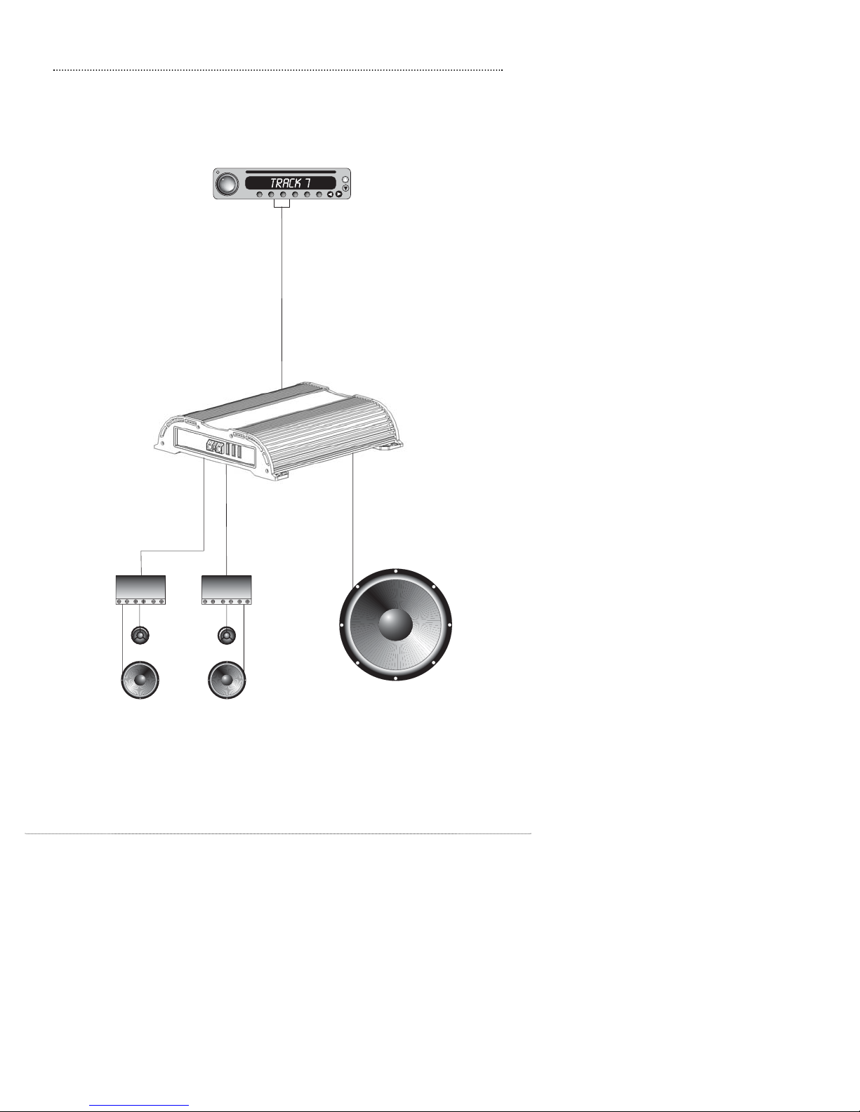
D5 4 Channel
2-way Component Set
With Passive Crossovers
Source Unit
RCA
Subwoofer
(4 Ohm Min. Impedence)
SYSTEM DIAGRAM 1
Diamond Audio Technology 12
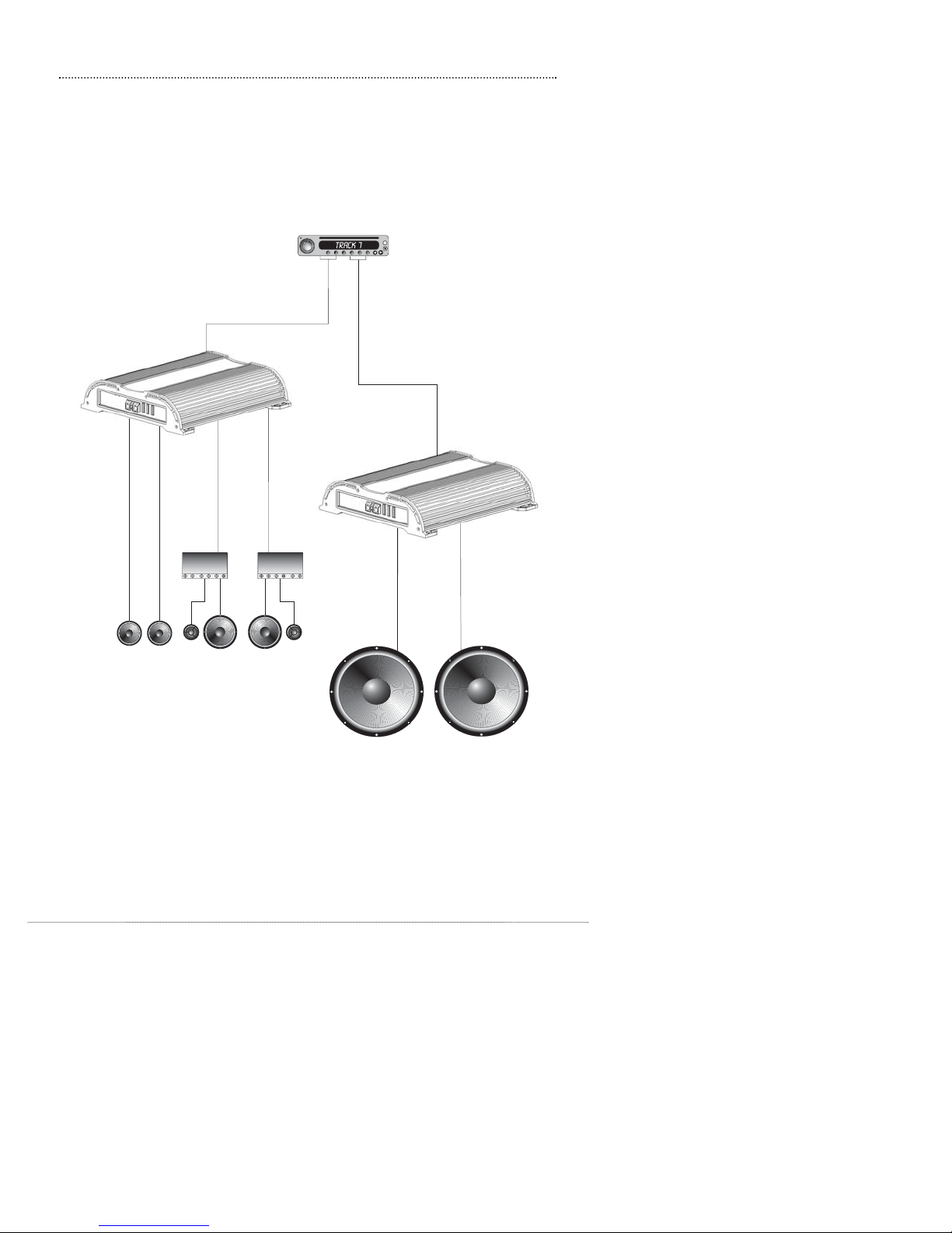
D5 4 Channel
Source Unit
2-way Comp.
Set With
Passive
Crossovers
Rear Fill
Subwoofers
(4 Ohm Min. Impedence each)
D5 4 Channel
Front
RCA
Rear
RCA
(bridged)
SYSTEM DIAGRAM 2
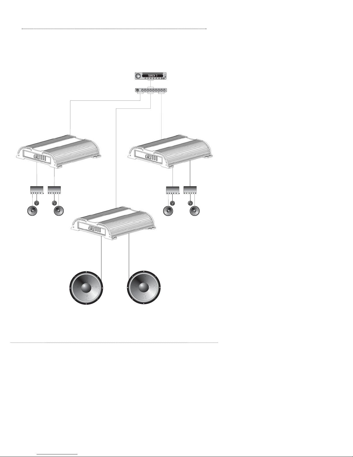
13 Diamond Audio Technology
2-way Component Set
with Passive Crossovers
2-way Component Set
with Passive Crossovers
Subwoofers
(4 Ohm Min. Impedence each)
D5 4 Channel
D5 4 Channel
Source Unit
Rear
RCA
Front
RCA
Sub
Out
EQ
D5 4 Channel
(bridged)
SYSTEM DIAGRAM 3
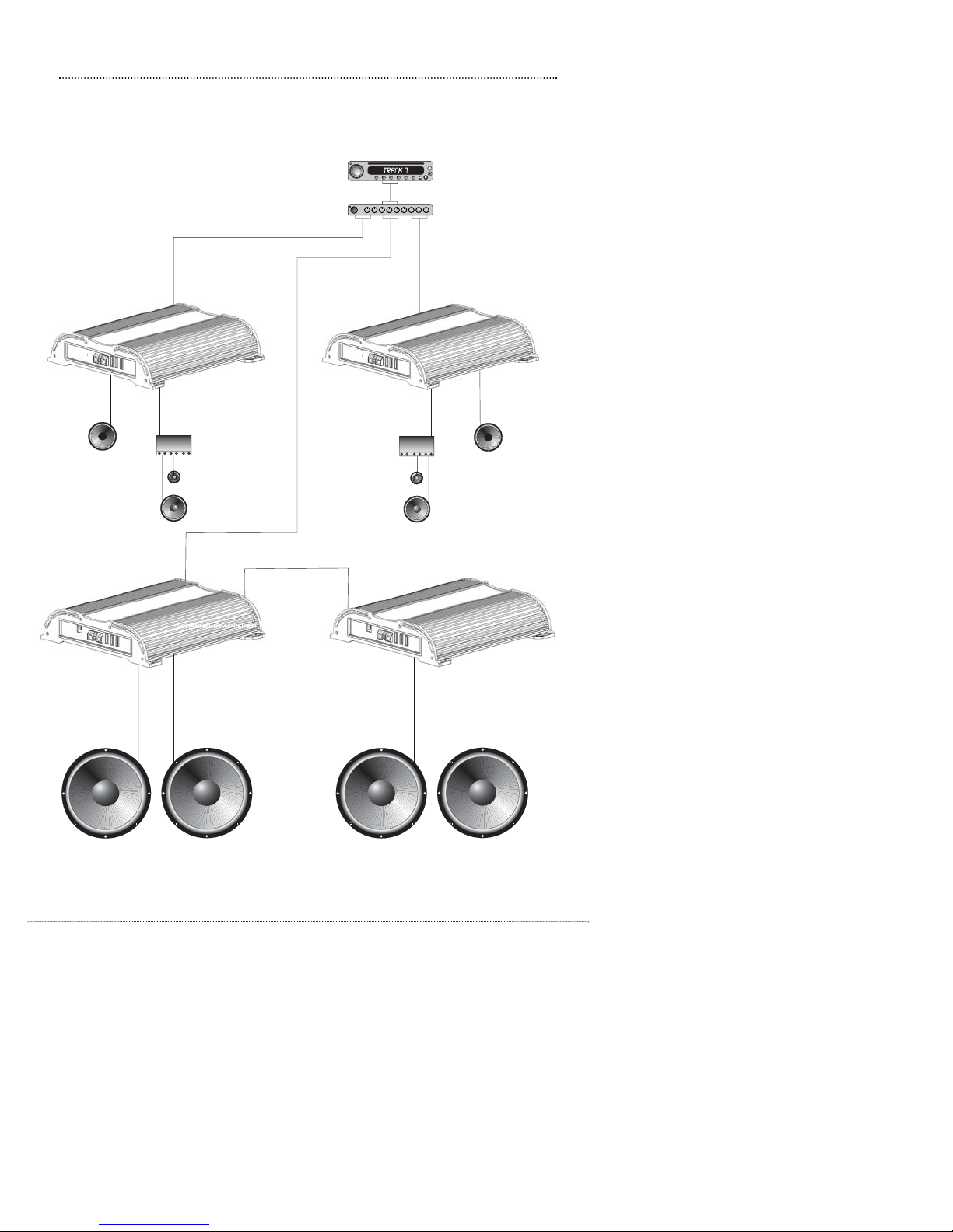
Diamond Audio Technology 14
2-way Component Set
with Passive Crossovers
2-way Component Set
with Passive Crossovers
Subwoofers
(1 Ohm Min. Impedence)
D5 Class "D"
Source Unit
Right
RCA
Left
RCA
Sub
Out
EQ
Subwoofers
(1 Ohm Min. Impedence)
D5 Class "D"
Rear Fill
Rear Fill
D5 4 Channel D5 4 Channel
(bridged)
(bridged)
SYSTEM DIAGRAM 4
This manual suits for next models
1
Table of contents
Other Diamond Audio Technology Car Amplifier manuals

Diamond Audio Technology
Diamond Audio Technology D5 5.1 User manual

Diamond Audio Technology
Diamond Audio Technology D7401 User manual

Diamond Audio Technology
Diamond Audio Technology D7152 User manual

Diamond Audio Technology
Diamond Audio Technology D5 1200.1 User manual

Diamond Audio Technology
Diamond Audio Technology D7056 User manual

Diamond Audio Technology
Diamond Audio Technology D5 300.2 User manual

Diamond Audio Technology
Diamond Audio Technology D7054 User manual

Diamond Audio Technology
Diamond Audio Technology D6 Series User manual


