Diamond Audio DAST12 User manual

POWERED ACTIVE
SPARE TIRE SUBWOOFER
POWERED ACTIVE
SPARE TIRE SUBWOOFER
DAST12DAST12

Specifications
All specifications subject to change without notice.
Power
THD
Signal to Noise Ratio
Frequency Response
Low Pass Filter 50Hz - 150Hz
Bass Boost
MODEL:
150W RMS/600W MAX
<0.5%
>90dB
20Hz - 150Hz
0 - + 12dB
DAST12
Subsonic Filter 20Hz (Fixed)
Diamond Audio Powered Active Spare Tire Subwoofer
Thank you for purchasing a Diamond Audio Powered Active Spare Tire
Subwoofer for your car audio system. You have chosen Diamond Audio
because you deserve the best!
Diamond Audio products are designed and engineered to the highest
quality standards in the industry to create the ultimate listening experience
in your vehicle. For optimal performance of this product, it is highly
recommended that you have your new subwoofer installed by an authorized
Diamond Audio dealer. Our authorized dealers have the necessary
experience and installation equipment to ensure that your subwoofer will
deliver maximum performance and explain all the details pertaining to your
warranty coverage as well.
If you decide to install the subwoofer by yourself, please thoroughly read
through this manual before getting started. This manual will help familiarize
yourself with this amplified subwoofer and guide you through the installation
process and procedures.
Please contact your local authorized Diamond Audio dealer if you
have any questions regarding the instructions in this manual or the
amplifier’s operation capabilities. If you require additional assistance,
please contact the Diamond Audio Technical Support Department
during business hours at 213-261-4161.
INTRODUCTION
2
Impedance 2 ohms
Dimensions 14.2” (360mm) x 5.9” (150mm)
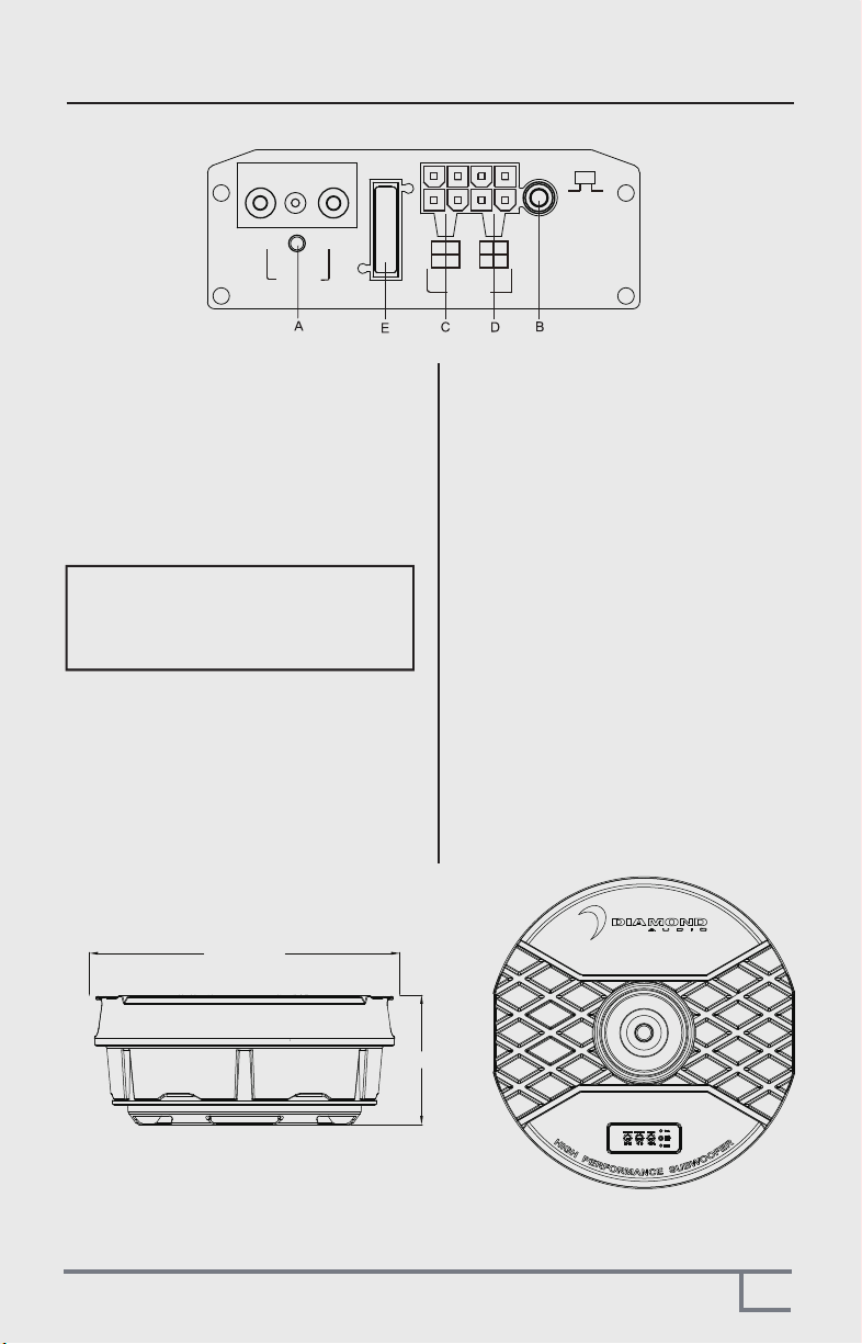
FEATURES / FUNCTIONS
3
A.POWER STATUS LED
AUTO POWER CIRCUIT
The AUTO POWER circuit is for high level
(speaker-level) connections. When the speaker
level connections are used AND the remote
turn on wire is NOT used the subwoofer will
AUTO POWER ON when signal is detected.
If the amplifier detected no signal input, the
amplifier will auto turn off.
You MUST use the Remote Control as this is
used to set up level and See G on its functions
B.REMOTE LEVEL CONTROL PORT
.
C.HIGH LEVEL (speaker level) INPUTS
If your head unit does not have RCA outputs
you can use the speaker outputs for the audio
source for the subwoofer. Use the supplied
cable and wire harness and connect the
outputs properly as shown in the connection
diagram in this manual (FIG2, PG5)
There is a GREEN “power” LED that glows
green when power is on and no problems are
present. If the protection circuit (PRO) comes
on, it will illuminate the other LED RED
E.FUSE
Do not use a fuse with a different value
and NEVER replace the fuse with a wire
or coin. The fuse is there to protect the vehicle
NOT the amplifer/subwoofer.
Note: Please connect the remote terminal
to the remote output of head unit as in
Fig.4. When you hear the unit turn ON/OFF
there should be a very slight POP noise
from the subwoofer.
D.LOW LEVEL RCA INPUTS
Low level inputs are the recommended way
to introduce the audio signal to the subwoofer.
IF RCA outputs are present on your head unit
or other signal source (such as a sound
processor - see FIG 1, PG4).
NOTE: NEVER CONNECT BOTH RCA AND
SPEAKER INPUTS SIMUALTANEOUSLY!!
POWER
GND +12V
REM
REMOTE
R-
R+
L-L+
FUSE
R-
R+
L-
L+
LOWHI
OFFON
INPUTS
AUTO
POWER ON
5.9"/150mm
Ø14.2" /360mm

INSTALLATION
4
Remote Control
REMOTE CONTROL
MIN MAX
White
Red
To audio
Low Outputs
L-CH
R-CH
White/Black(L-)
White(L+)
Gray/Black(R-)
Gray(R+)
To Audio Hi Outputs
To REMOTE TURN-ON
Terminal Of Head Unit
Chassis
Ground
Point
Chassis
Ground
Point
Battery Fuse
POWER
GND +12V
REM
REMOTE
R-
R+
L-L+
FUSE
R-
R+
L-
L+
LOWHI
OFFON
INPUTS
AUTO
POWER ON
PANEL CONNECTIONS AND FEATURES
Low Level Input Wiring
Low-level (RCA) input wiring is preferred for best audio performance. Most trunk
or hatchback installations will require a 15-20 foot RCA cable, Always use a high
quality cable.
NOTE: Do not connect BOTH the high level and low level inputs from your
receiver to your amplifier at the same time!
SPECIAL NOTE: Always route power and signal seperately
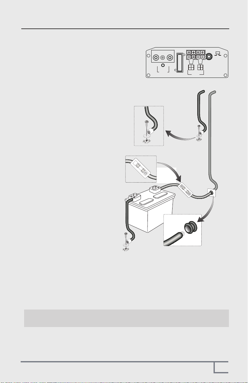
POWER AND INPUT SIGNAL WIRING
NOTE: DO NOT USE CCA wiring kits EVER!!!!!
Using this type of wire VOIDS your warranty!
1. Connect your 8 guage power wire
DIRECTLY to the battery B+ terminal
with a high quality ring terminal. Make
sure that a fuse holder is approx. 18
inches from the battery and the fuse
should be NO larger than 20 amperes.
2. Make sure to run the power wire thru a
gromment in the firewall to eliminate any
possiblitity of shorts.
3. Route the Remote Control cable (phone
wire) thru your vehicle to the sparetire
area of you trunk.
4. Connect a remote turn on wire to your
head units remote output using 16
gauge blue wire (not included)
SPECIAL NOTE:
The DAST12 is equipped with an
automatic turn on circuit if NO
switched 12 volts is available for
turn-on.
Power wiring is very straight forward. Use a high
quality power kit (not supplied or included)
INSTALLATION
5
POWER
GND +12V
REM
REMOTE
R-
R+
L-L+
FUSE
R-
R+
L-
L+
LOWHI
OFFON
INPUTS
AUTO
POWER ON
The trunk: Shown is a
hatchback,. But Coupes or
Sedans should be almost
identical
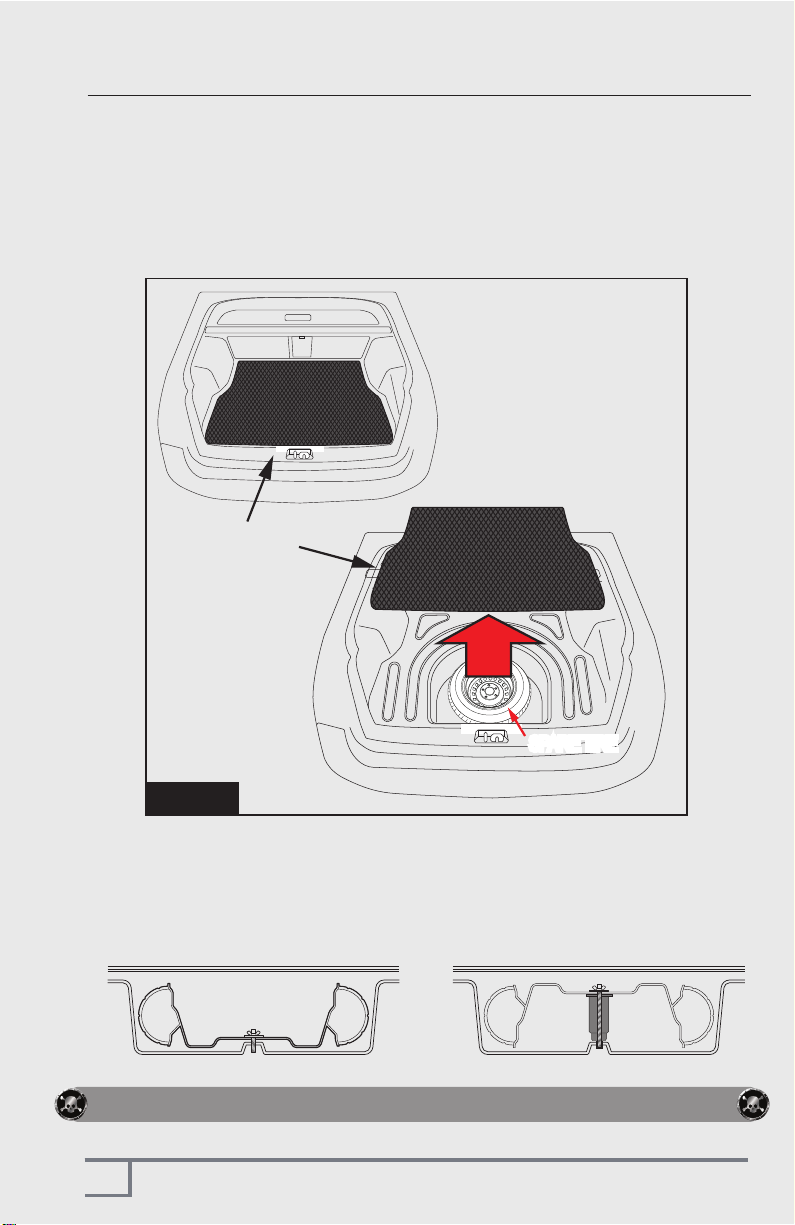
Figure 1
CAUTION!! Make sure to not drill or screw into vital vehicles components!!
SPARE TIRE
SPARE TIRE
This is a VERY simple install and can fit into virtually any car made in the last 10 years.
WITHOUT removing your spare tire. Follow the instructions to a SUPER easy install!
1. Remove the trunk liner. Typically it is NOT screwed or bolted down. It should
simple pull out as shown below in Figure 1
TRUNK LINER
2. Once the trunk liner is removed and you can get access to your spare tire
Make a mental note if the spare tire is deep side down or deep side up???
Deep Side Down Deep Side Up
INSTALLATION
6
INSTALLATION
7
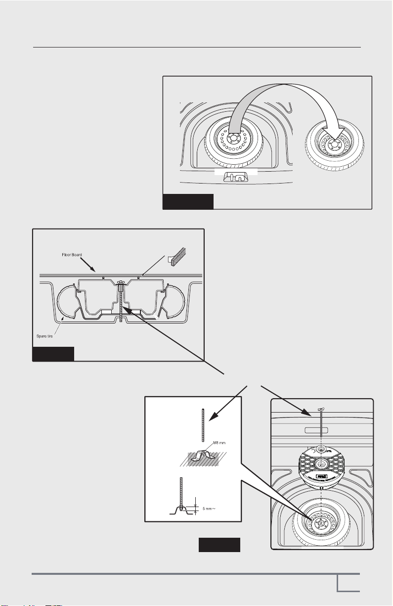
Figure 2
Figure 3
Figure 4
FLIP OVER THE SPARE TIRE - IF NEEDED
1. IF your spare tire is Deep
Side UP then you need to
unbolt it and flip it over so
the DAST12 can sit inside of it.
(See Figure 2)
2. IF your spare tire is Deep
Side DOWN then you simply
need to unbolt the sparetire
and drop the DAST12 in so
it can sit inside of it.
(See Figure 3)
NO NEED TO FLIP OVER THE SPARE TIRE
2. Make sure to check
what size the mounting
bolt is as the DAST12
comes with a 8mm and
a 10mm mounting bolt.
Which should fit 90% of
all vehicles out today.
8mm or 10mm Mounting Bolt
(included)

INSTALLATION
8
Using fix bolt and ABS Nut(supplied)
SPARE TIRE WITH ABS NUT (AUDI/VW TYPICALLY)
Some vehicles have a different type of spare tire mounting system as shown below.
Where there is a large “NUT” and a bolt coming thru the center of the spare tire.
IF so....
1. Thorughly clean the spare tire
2. Replace the original spare ABS fixing nut with the supplied one that came with
the DAST12
ORIGINAL OEM ABS NUT
CERWIN VEGA
REPLACEMENT ABS NUT
(included)
CONNECTING WIRING HARNESS
1. Insert the Power/input plug in the socket in the handle area, making sure it "clicks"
in place. Once it is plugged in, wrap all the wires neatly so that it is easy to unplug and
remote the unit when necessary.
2. The DAST12 can now be mounted into the spare tire, please make sure no wires are
caught or pinched under or on the side of the unit.
Figure 5

A m plifier w ill n o t
p o w er u p .
P ro tectio n L E D
co m es o n w h en
am p lif ier is
p o w ered u p
No o u tp u t.
L o w o u tp u t.
Hig h h iss in th e
so u n d .
S qu ealin g n o ise
is p rese n t.
Dis to rted so u n d .
A m p lifi er g ets
v ery h o t.
E n g in e n o ise
(sta tic ty p e )
E n g in e n o ise
(altern ato r w h in e)
S Y MP T O M P O S S IB L E R E ME D Y
Check to make sure you have a good ground connection.
Check that there is at least 12v on the battery (+) terminal
Check that the Remote Input (Turn-On) has at least 10VDC.
Check that the green power LED is lit
Check all fuse, replace if necessary.
Make sure that the Protection LED is not illuminated. If it is lit, shut off
the amplifier briefly, and then Power Cycle (reset).
Turn down the volume control on the head unit to prevent overdriving
the input speaker leads,
Try Power cycling (reset) the amplifier. If the Protection LED still comes
on, then the amplifier is faulty and needs servicing
Check that all fuses are OK.
Check that the power light in on
Check that unit is properly grounded.
Check that the Remote Input (Turn-On) has at least 10VDC.
Check that the input signal connections are plugged in properly.
Readjust the Input Gain Control.
Check the Crossover Control settings, possibly try a higher frequency.
Disconnect all RCA inputs to the power sub's control panel. If the hiss
disappears, then plug in the component driving the amplifier and unplug its
inputs. If the hiss disappears at this point, go on until the faulty/noisy
component is found.
Reset Input Gain. It is best to set the subwoofers input level control as low as
possible. The best subjective signal-to-noise ratio is achieved in this manner.
Try to set the head unit as high as possible (without distortion) and the
subwoofer input level as low as possible.
Check for improperly grounded RCA interconnects. Or possible “blown”
signal ground from headunit. (Some headunits are notorious for this!)
Check that the Input Gain control is set to match the signal level of the head
unit. Always try to set the Input Gain on the subwoofer as low possible. Input
gain is NOT power output!! Check that all crossover frequencies are properly
set.
Readjust the Input Gain Control.
Make sure to NOT use CCA power wire as it will cause these issues alsofrequency.
This is usually caused by poor quality RCA cables, which can pick up
radiated noise. Use only the best quality cables, and route them away
from power cables.
Check that the RCA grounds are not shorted to the vehicle chassis
Check that the head unit is properly grounded.
If you experience operation or performance problems with this product, compare
your installation with the electrical wiring diagram on the previous pages. If problems
persist,read the following troubleshooting tips which may help eliminate the problems.
TROUBLESHOOTING
9
3761 South Hill St.
Los Angeles, CA 90007
WARRANTY
10

NOTES
11

©2021 CVDA Inc. All Rights Reserved.
(a division of CV & DA Holdings, Inc.)
©2021 Diamond Audio. All Rights Reseved.
(a division of CV & DA Holdings, Inc.)
3761 South Hill St.
Los Angeles, CA 90007
Table of contents


