Diamond Dust CW Kit User manual

Diamond Dust CW Kit
_________________ ASSEMBLY MANUAL ________________
Specifications
Wingspan: ……………… 29.75 in (755.65mm)
Length: .…………………. 24.50 in (622.30mm)
Wing A ea: ……….……. 468 sq in (30.19 sq dm)
Weight: ………………… 2.25 – 3.0lbs (1020g–1360g)
Engine size: ………………… .25 - .40 2 cycle
Wing Loading …………………… 12oz/SF
Radio: ………………… 4-channel w/3 se vos

2
Table of Contents
Introduction . . . . . . . . . . . . . . . . . . . . . . . . . . . . . . . . . . . . . . . . . . . . . . . . . . . . . . . . . .
Warranty Information . . . . . . . . . . . . . . . . . . . . . . . . . . . . . . . . . . . . . . . . . . . . . . . . . .
Contents of Kit . . . . . . . . . . . . . . . . . . . . . . . . . . . . . . . . . . . . . . . . . . . . . . . . . . . . . . . .
Required Radio and Engine. . . . . . . . . . . . . . . . . . . . . . . . . . . . . . . . . . . . . . . . . . . . . .
Additional Required Tools and Adhesives. . . . . . . . . . . . . . . . . . . . . . . . . . . . . . . . . . .
Section 1: Framing of the Airframe . . . . . . . . . . . . . . . . . . . . . . . . . . . . . . . . . . . . . . . .
Section 2: Elevon Construction . . . . . . . . . . . . . . . . . . . . . . . . . . . . . . . . . . . . . . . . . . .
Section 3: Vertical Fin Assembly . . . . . . . . . . . . . . . . . . . . . . . . . . . . . . . . . . . . . . . . . .
Section 4: Installing the Control Horns and Elevon Linkage. . . . . . . . . . . . . . . . . . . . . .
Section 5: Equipment Placement and Pre-Balancing. . . . . . . . . . . . . . . . . . . . . . . . . . .
Section 6: Covering the Aircraft. . . . . . . . . . . . . . . . . . . . . . . . . . . . . . . . . . . . . . . . . . .
Section 7: Fuel Tank Installation . . . . . . . . . . . . . . . . . . . . . . . . . . . . . . . . . . . . . . . . . .
Section 8: Final Equipment Installation. . . . . . . . . . . . . . . . . . . . . . . . . . . . . . . . . . . . . .
Section 9: Final Inspection / Control Throws. . . . . . . . . . . . . . . . . . . . . . . . . . . . . . . . . .
Section 10: Balancing the Diamond Dust. . . . . . . . . . . . . . . . . . . . . . . . . . . . . . . . . . . .
Section 11: Pre-Flight & At the Flying Field . . . . . . . . . . . . . . . . . . . . . . . . . . . . . . . . . .
3
4
5
6
7
8
33
37
40
44
45
50
51
54
55
56

3
Introduction
Thank you for purchasing the Diamond Dust Clipped Wing Kit high performance delta wing
aircraft. Backed by Diamond Dust’s high quality reputation, the Diamond Dust CW will
provide you with the superior performance and features you are looking for in a high speed
high performance aircraft. The Diamond Dust CW features lightweight balsa, composite
tubes, and light-ply construction. This lightly loaded delta wing design makes it ideal for
extremely aggressive maneuvers as well as excellent low speed maneuverability.
Before Starting Assembly
Before beginning the assembly of your Diamond Dust CW, remove each part from the box
and the parts bag for inspection. Closely inspect the wood pieces and parts bag for damage.
If you find any damaged or missing parts, contact the place of purchase.
Using the Manual
This manual is divided into sections to help make assembly easier to understand and to
provide breaks between each major section. Remember to take your time, and follow the
directions closely. You can also check on the Diamond Dust RC website for any updates to
this manual at www.diamonddustrc.com.
Also there are a number of steps in the assembly of the Diamond Dust and Diamond Dust
Clipped Wing version that are identical. For practicality and efficiency reasons, some pictures
in this manual may show the Stock Diamond Dust in the illustrations. This should not be a
problem since the majority of the steps are identical for both aircraft. If you have any
questions, please don’t hesitate to contact our tech support line at (352-871-7301)
Monday through Friday, between the hours of 8am to 6pm EST.

4
Warranty Information
Tetracam, Inc. and Diamond Dust RC, guarantees this kit to be free from defects in both
material and workmanship at the date of purchase. This warranty does not cover any
component parts damaged by use or modification. In no case shall the liability to Tetracam,
Inc. exceed the original cost of the purchased kit. Further, Tetracam, Inc. reserves the right
to change or modify this warranty without notice.
In that Tetracam, Inc. and Diamond Dust RC have no control over the final assembly or
materials used for the final assembly, no liability shall be assumed nor accepted for any
damage resulting from the
use of the final assembled product . By the act of using the assembled product, the user
accepts all resulting liability. Please note that once assembly of the model has been
started, you must contact Tetracam, Inc. directly regarding any warranty questions. Please
do not contact your local hobby shop regarding warranty issues, even if that is where you
purchased it. This will enable Tetracam, Inc. to better answer your questions and service you
in the event that you may need any assistance. If the buyer is not prepared to accept the
liability associated with the use of this product, the buyer is advised to return this
kit immediately in new and unused condition to the place of purchase.
Warning
An RC aircraft is not a toy! If misused, it can cause serious bodily harm and damage to
property. Fly only in open areas, perferably at AMA (Academy of Model Aeronautics)
approved flying sites, following all instructions included with your radio and equipment.
Tetracam, Inc
Devonshire St.
Suite 310
Chatsworth, CA 91311
Sales - (818) 718 -2119
Tech Support – (352) 871-7301
www.tetracam.com

5
Contents of Kit – Diamond Dust CW
Main Box
Qty Description
1 Assembly manual
1 Blueprint / Plan
2 14 ¼” Main wing spars (Front &
Rear)
2 Rear main spar extenders Tubes
(.300” x 6-3/4)
2 Approximately 23” Leading Edge
tubes (.300” O.D.)
2 Root ribs (#1 Ribs)
2 Mid wing ribs (#2 Ribs)
2 Tip ribs (#3 Ribs)
1 1/16” Balsa partial rib
1 1/8” Plywood engine mount
1 1/8” Plywood engine mount doubler
1 1/8” x 3-7/8” x 1-3/4” Plywood switch
plate
2 Balsa Wing tips (Precut 1/4”x1-1/2”
elevon stock)
2 Elevon stock (1 ½” x 3/8” )
6 ½” x 1/16” x 36” Balsa cap strips
8 4” x 4-5/8” x 1/16” Balsa sheets
1 4/ x 4-5/8” x 1/16” Balsa sheet with
precut slots.
2 1/8” precut vertical fin (front half)
2 1/8” precut vertical fin (rear half)
1 ¼” x 3/8” Balsa trailing edge
stock
3 ¼” x ¼” x 36” Balsa triangle stock
1 1/16” x 1-3/4” x 4” Balsa fuel tank
compartment rear bulkhead
1 3/16” Antenna tube 36”
1 1/32” antenna pull tube 36”
1 Diamond Dust CW decal
2 4-40 Pushrods
1 2-56 Pushrod
2 Composite pushrod stiffener tubes
Qty Description
2 1/8” x 1/8” Bass wood coving stock
(For Leading Edge)
1 6oz Fuel tank with hardware
2 .005” Carbon fiber Strip (1/4”x34”)
Hardware Bag
Qty Description
1 1/8” x ¾” x 3-7/8” Plywood firewall
2 ¼” x ¼” x 4-3/8” Hardwood servo rails
2 ¼” x ¼” x 7/8” Hardwood servo rails
4 1/8” x 1/8” x 4” balsa fin offset spacer/
Fin cap strip.
4 1/8” x ¼” x ½” Plywood spar end / rib
locking tabs
4 1/8”thick 1 ¼” x 1 ¼” Triangle gusset
1 Spool Kevlar thread
10 CA Hinges
11 #19 Rubber bands
2 HD Control horns with base plate
2 4-40 Ball links
2 #4 Ball Link bushing
1 2-56 Nylon clevis
1 1” wide x 15’ roll of Solartex
8 4-40 x 1” Socket head cap screw
2 4-40 x 5/8” Socket head cap screw
2 4-40 Nylon insert locknut
1 Velcro strip

6
equired adio and Engine
Radio Equipment
•4-channel radio system (minimum)
•2 High torque digital servos (JR9411
recommended or equivalent)
•1 HS 85MG or equivalent mini servo
Engine / Power System
Any .25 to .40 two stroke RC engine
(Recommended Items)
SERVOS
Throttle:
JR: 331Micro or 3121 Mini
Hitec: HS-85MG Mini servo
Elevon .28 and under:
JR: DS537
Hitec: HS475
Elevon .30and above:
JR: DS9411 or DS8611A
Hitec:
HS-7985MG
NOTE: Since there are so many servo choices
available, please compare and match as
closely as possible, the specifications of the
above mentioned servos with the servos you
intend to use

7
Additional equired Tools and Adhesives
Tools
•Drill
•Drill bits: 1/16”,3/32”, 7/64”, 1/8”
•Hobby Knife
•Razor saw or hacksaw
•#2 Phillips Screwdriver
•120 or 240 grit sandpaper
•Sanding Block or Permagrit File
•Scissors
•3/32” hex driver or Allen wrench
•Pliers
•Ruler or measuring tape
•Speed square or small square
•Soldering Iron
•Heat Gun
•Covering Iron
•Pencil
Adhesives
•Thin CA Glue (Cyanoacrylate)
•Thick CA Glue (Cyanoacrylate)
•CA Accelerator
•CA Remover / Debonder
•Stix-It Covering Adhesive
Other Required Items
•Wax paper or Parchment paper
•Foam pad or rubber pad for fuel tank
•Epoxy Brushes

8
Section 1: Framing of the Airframe
Step 1
Locate all parts listed in materials list, and
take inventory of all parts. This will help you
familiarize yourself with the various
components.
Lay your print out on large flat surface ( the
larger and flatter the better). Cover your
plans with either parchment paper or wax
paper and tape them down to secure to your
work surface.
Step 2
Assemble the rear spar by locating the tubes
labeled “Rear Spar” and “Spar extenders”.
Insert the spar extenders into each end of the
rear spar. You may have to lightly sand the
spar extenders so that they go into the rear
spar with a moderate amount of force, but
first try the opposite end of the spar extender
tube to see which end fits the best.
9
Section 1: Framing of the Airframe – Cont.
Step 3
Lay the assembled spar on the print to see
how far the tubes should fit into one another.
Adjust both sides so the center main spar is
centered on the print and the end tubes
extend to the correct length shown on the
print (be as precise as possible when
matching the print through all the steps).
When the rear spar matches the print (tube
engagement and overall length), apply a drop
of thin C.A. on each joint.
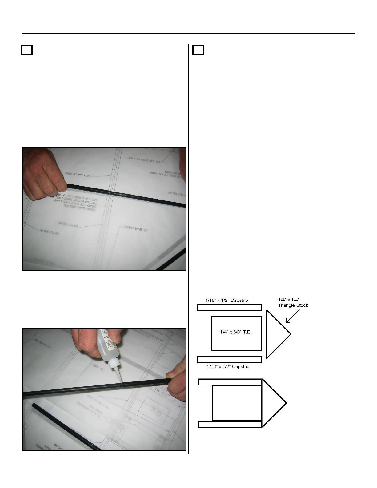
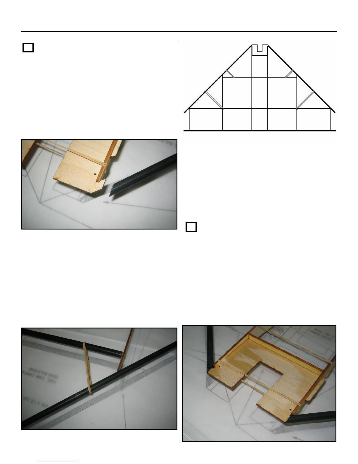
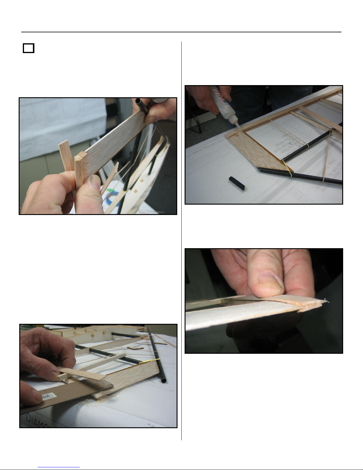
Step 4
Find the ¼” x 3/8” x 36” balsa stick trailing
edge (T.E) and cut it the same length as
shown on the plan.
Find one of the ¼” x ¼” x 36” triangle stock,
and also cut it to match the trailing edge you
just cut. Center the triangle stock on the ¼”
side of the ¼” x 3/8” T.E. Glue the triangle
stock to the ¼” side with thick CA.
Next, find two 1/16” x ½” cap strips that seem
to be the stiffest from the wood supplied with
the kit. Cut them to match the length shown
on the plans.
NOTE: Do not glue the T.E. cap strips
beyond the #2 ribs until the wing tips are
installed in step #16.
Examine the drawing below to ensure proper
assembly of the T.E assembly.
When you are done assembling the T.E.,
set it aside until step 10.

10
Section 1: Framing of the Airframe – Cont.
Step 5
Take the two center ribs (rib #1) and locate
the square 1/4 x 1/4 servo rail holes. Note:
the square holes are closest to the top
side of the airfoil.
Next, hand slide the front and rear spars
onto the center ribs (#1 ribs). Align the ribs
and position them as shown on the print.
Do not glue anything yet!!!
Step 6
Install one #19 rubber band (included) over
each rear spar half and one rubber band
over each forward spar half, as shown
below. Note: you will need to double turn
the rubber bands that go over the forward
spar halves.
Next, slide the #2 ribs over the rear spar.
Add one more rubber band to each side of
the rear spar and one diagonally around the
rear spar and rib #2, as shown below.
Section 1: Framing of the Airframe – Cont.
11
Step 7
Place the engine mount in between the two
#1 ribs. You will first have to insert the front
part of the #1 ribs into the front part of the
mount in order to clear the leading edge
locking tabs.
Next, temporarily secure the mount into
position by using one #19 rubber band
around it and the #1 ribs
.
You will have to
double the turns on the rubber band in order
to achieve a strong hold
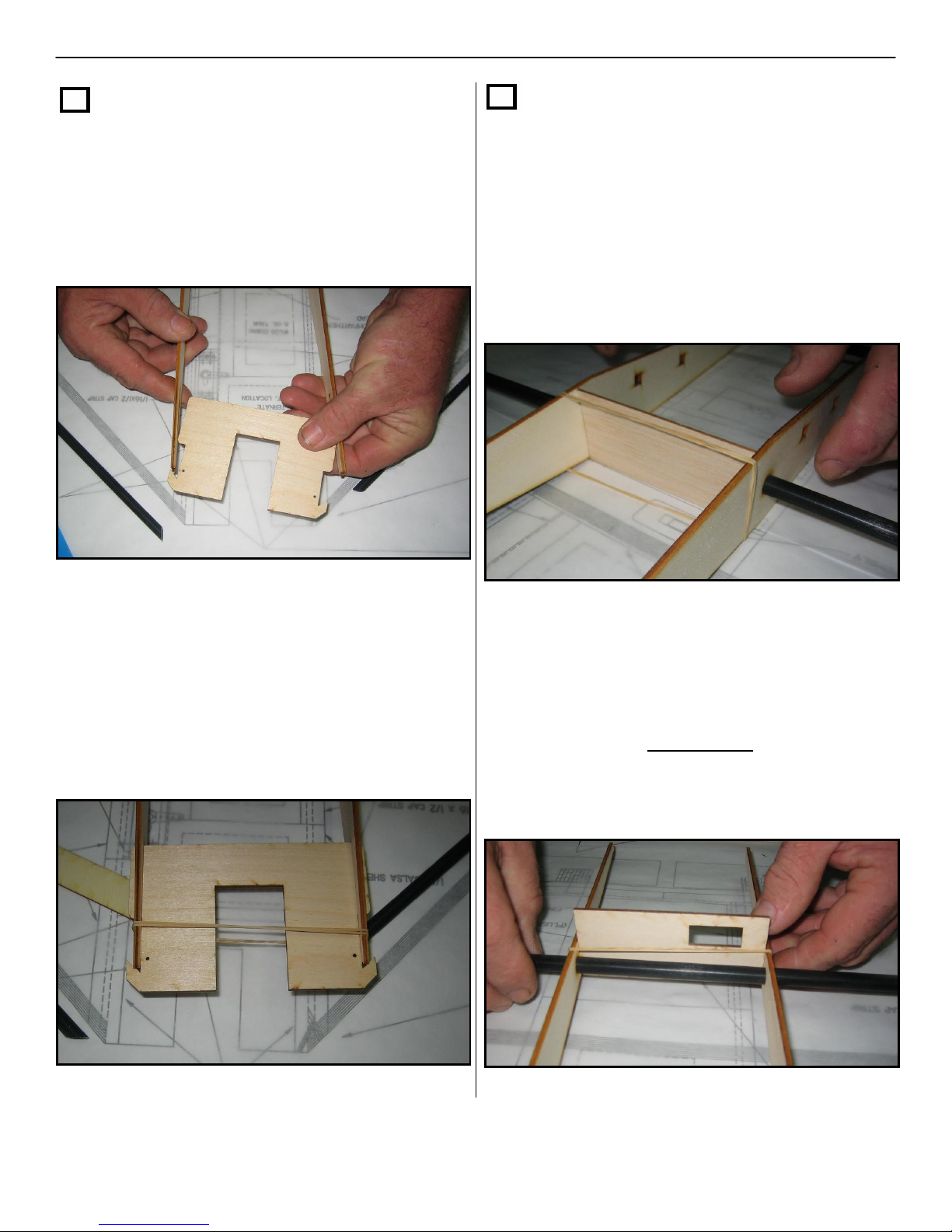
Step 8
Take the 1/16” x 1-3/4” x 4” balsa fuel tank
c
ompartment rear bulkhead
and lay it
vertically against the front of the front spar
between the #1 ribs. Place a #19 rubber
band around the ribs to secure the bulkhead
as a spacer. You may have to double the
turns on the rubber band in order to achieve
a strong hold. Do not glue yet!!!
Next take the 1/8” x 3-7/8” x 1-3/4” plywood
switch plate and place it vertically on the
rear spar between the #1 ribs. Place a large
rubber band around the ribs to secure the
switch plate as a temporary spacer.
NOTE: Do not glue this plate to the ribs
or rear spar !!!
12
Section 1: Framing of the Airframe – Cont.
Step 9
Center the forward spar with the alignment
hole in the #2 rib (centered top and bottom),
and insert one of the 1/8” x ¼” x ½”
plywood spar end / rib locking tabs through
the rib and into the spar. Put a few drops of
thin CA where it is connected. Repeat on
the opposite side.
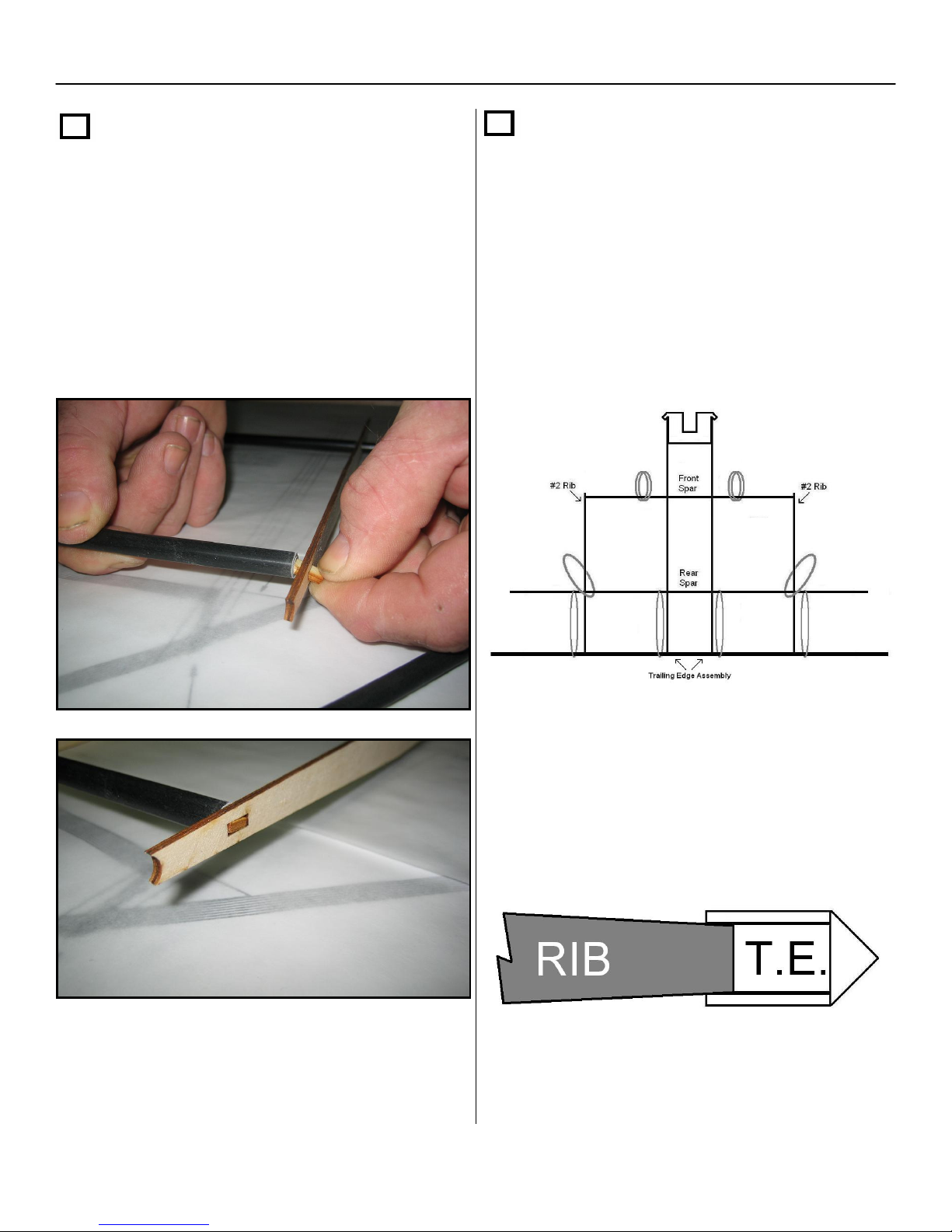
Step 10
Take the trailing edge assembly from step 4
of this section and slide it through the four
#19 rubber bands that are on the rear spar.
Place the rubber bands so they are
alongside the #1 ribs and on both sides of
the #2 ribs, as shown below. Line up all
spars and ribs to match the print as
precisely as possible.
When in place, put a drop of thin CA at
each rib to tack in place.
Note: the trailing edge of the ribs should
self center in between the 1/16” cap strips
on the T.E assembly.
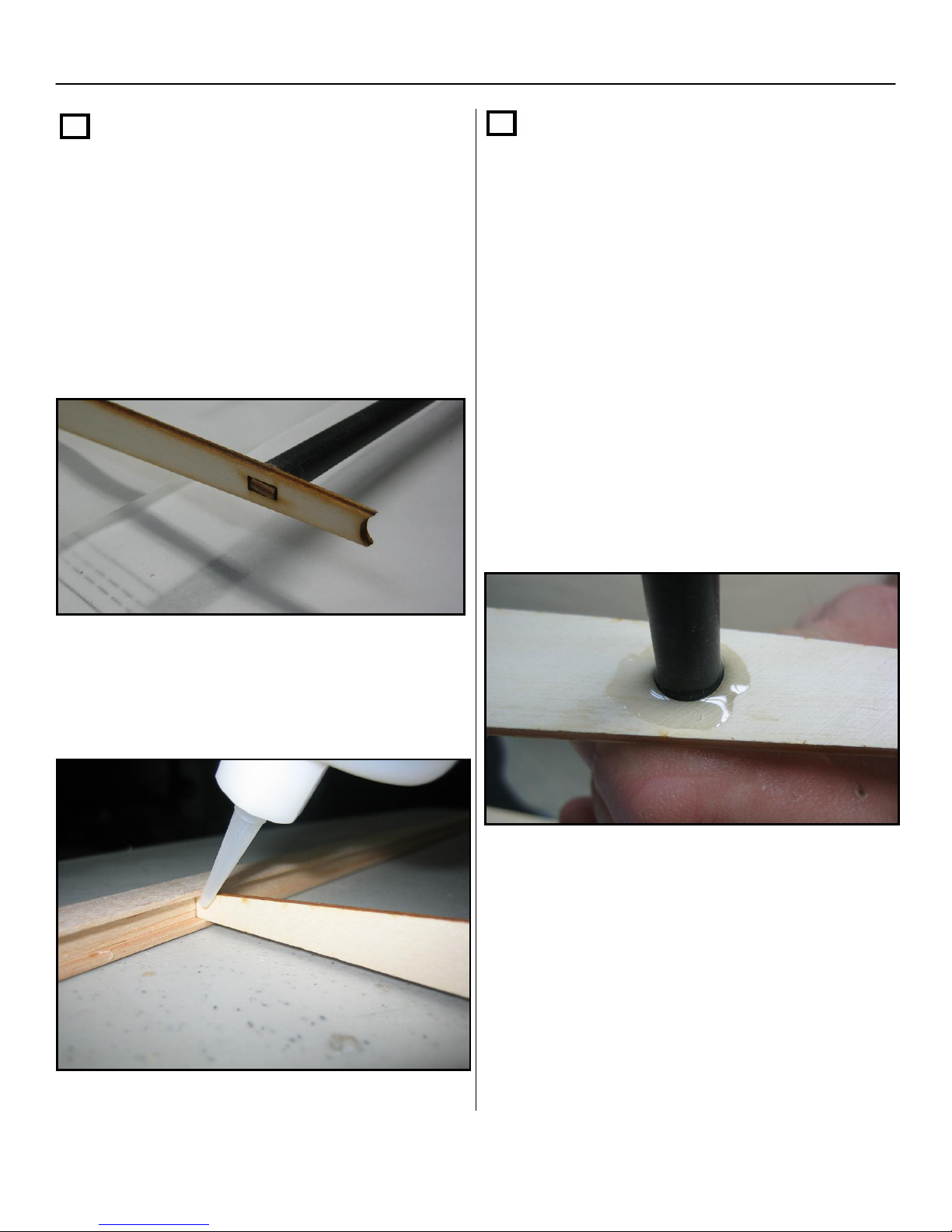
13
Section 1: Framing of the Airframe – Cont.
Step 11
Square up and center the #3 rib on the T.E
and the rear spar extender. Next, insert the
wood tab through the #3 rib into the rear
spar extender. When everything is aligned
and square, first glue with thin CA and then
with thick CA. Repeat this step for the
opposite side.
Make sure that everything lines up on the
print and finish gluing all ribs to the trailing
edge.
Step 12
NOTE: be careful not to glue the
temporary spacers at the spars or the
rubber bands.
Make sure the fuel tank compartment rear
bulkhead is square and then first glue with
thin CA then with thick CA.
Next, glue the main ribs to both the forward
and rear spars first using thin CA, then fill in
around the spars with thick CA.
You can now cut the four rubber bands that
hold the T.E. assembly. Keep the remaining
rubber bands on the airframe, since you will
need these to install the leading edges of the
aircraft.
14
Section 1: Framing of the Airframe – Cont.
Step 13
Next you will be installing the leading edges
on the airframe. Find the two tubes labeled
“L.E. Tubes” and slide each one through the
double rubber bands attached to the forward
spar halves. Make sure the 45 degree cuts
are facing the motor mount.
Insert the L.E. tube into the angled motor
mount tabs and rest the tube on both the #2
and #3 ribs.
Note you may have to slide the rubber band
back in order to increase the tension
between the L.E. and the front spar.
Once you have both leading edges aligned
and sitting on both the #2 and #3 ribs, place
a drop of thick CA on both sides of the #2
and #3 ribs at the leading edge. The square
end of the L.E. tube will extend beyond the
wing tips. Leave this extra length for now.
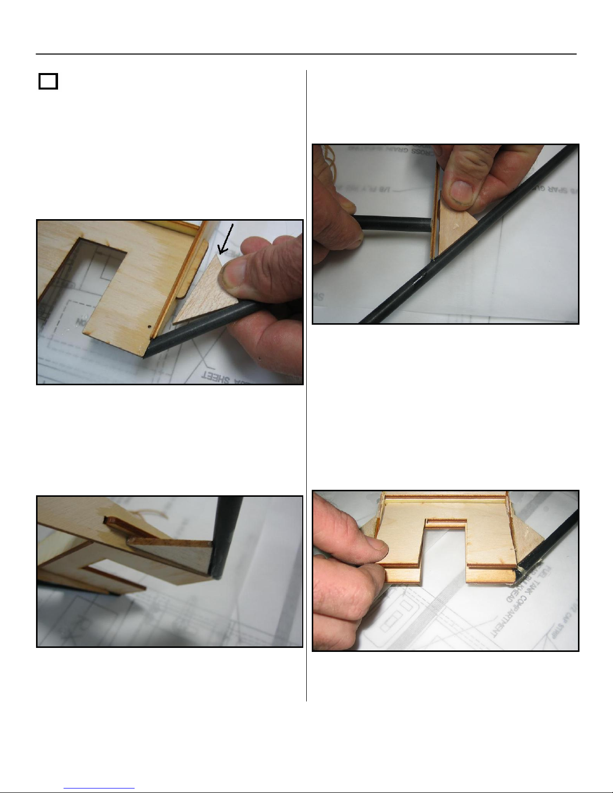
Step 14
Next, Locate the
1/8” x ¾” x 3-7/8”
plywood firewall and center it between the
#1 ribs and the motor mount plate. Apply
glue
on both sides, where the firewall
intersects the #1 ribs and where it touches
the motor mount, with both thin and then
thick CA. Then, cut the rubber bands holding
the motor mount.
15
Section 1: Framing of the Airframe – Cont.
Step 15
Locate the triangle gussets from the parts
bag. The first ones are installed behind the
leading edge at the motor mount. Glue
them in with thick CA in the location shown
on the plans.
Note: the forward gusset should be
installed underneath the protruding tab from
the motor mount while the airframe is in the
upright position.
Next glue the triangle gussets, that are
positioned behind the L.E. and on the outside
of the #2 ribs, with thick CA.
NOTE: make sure you glue both the top
and bottom sides of gussets where they
connect to the leading edge and ribs.
Now add the motor mount doubler plate to
the bottom of the motor mount. Glue in using
thick CA all around the bottom of the motor
mount and clamp tight until the glue dries.
16
Section 1: Framing of the Airframe – Cont.
Step 16
Locate the two p
recut 1/4”x1-
1/2” elevon
stock / balsa wing tips, with
the 38 degree
angle on one end, and place the square end
between the TE cap strips with the 38
degree angle cupped into the rear side of
the leading edge on the outside of rib #3.
Glue in place first with thin CA and then add
thick CA where the balsa meets the
backside of the L.E. Repeat this step for
both sides. NOTE: Do not glue the 1/16 x
½ “cap strips on the trailing edge
assembly yet!
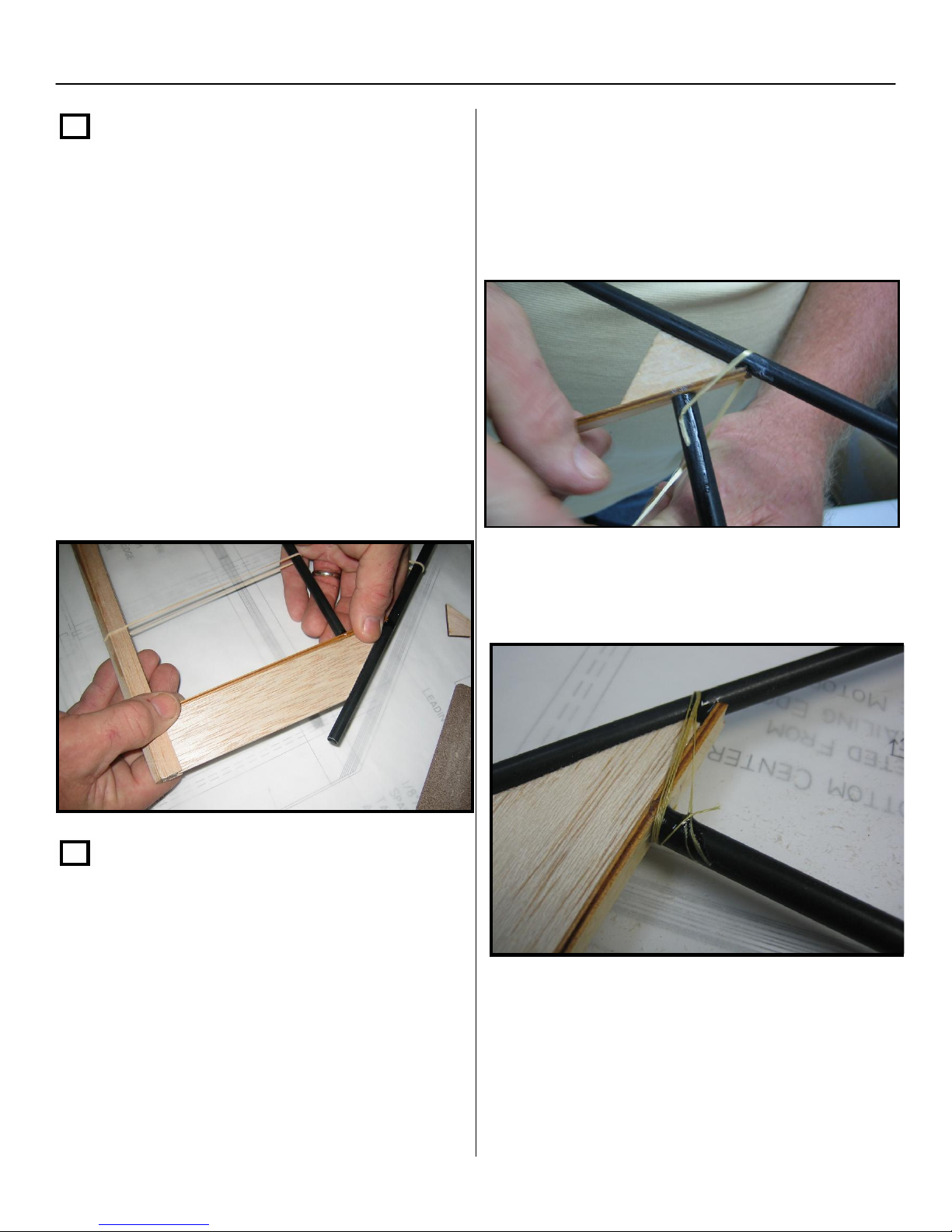
Step 17
Locate the Kevlar thread in the parts bag.
Following the illustrations on the print, first
wrap the #2 and # 3 ribs where they
intersect the L.E. Make sure you reference
the print first before starting, to ensure that
you will be installing the Kevlar at the proper
angles.
Place a drop of thin CA on the spar tube and
lay the tip of the Kevlar thread in the glue
drop and allow it to dry. This will hold the
Kevlar in place while you wrap the thread
around the ribs and L.E. and spar.
Next, wrap 5 to 6 turns around the rib, L.E.
and spar, while holding the Kevlar thread
tight.
Once wrapped, soak the entire Kevlar thread
with thin CA. Repeat this step for all four
points where the ribs and L.E. intersect, as
shown on the print. NOTE: You can now
cut the four rubber bands that hold the
leading edge tubes.
17
Section 1: Framing of the Airframe – Cont.
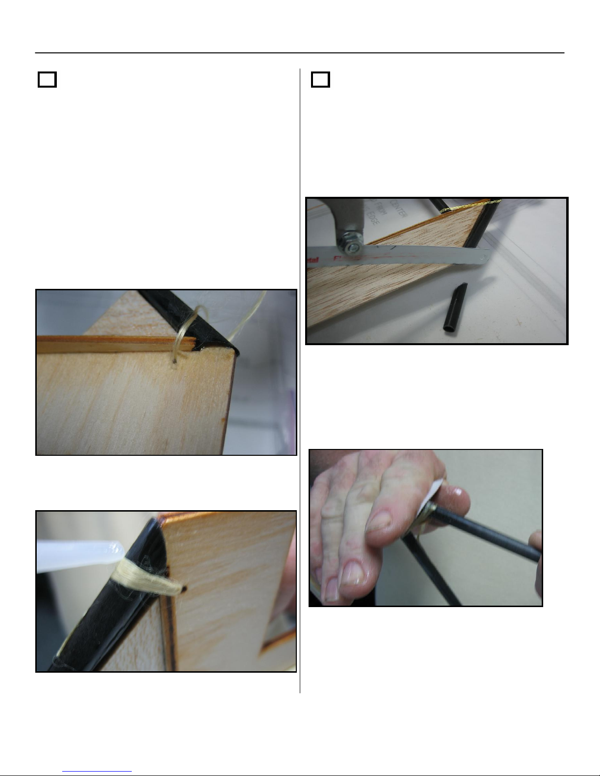
Step 17 – Cont.
Next, thread the Kevlar through one of the
small laser cut holes found on the motor
mount and wrap it around the leading edge
and motor mount 5 or 6 times while
reinserting it through the laser cut hole. Glue
it in with thin CA.
NOTE: you may have to re-drill the holes
since the laser cut hole may have been filled
in with glue from step 15
Repeat this for both sides of the motor
mount.
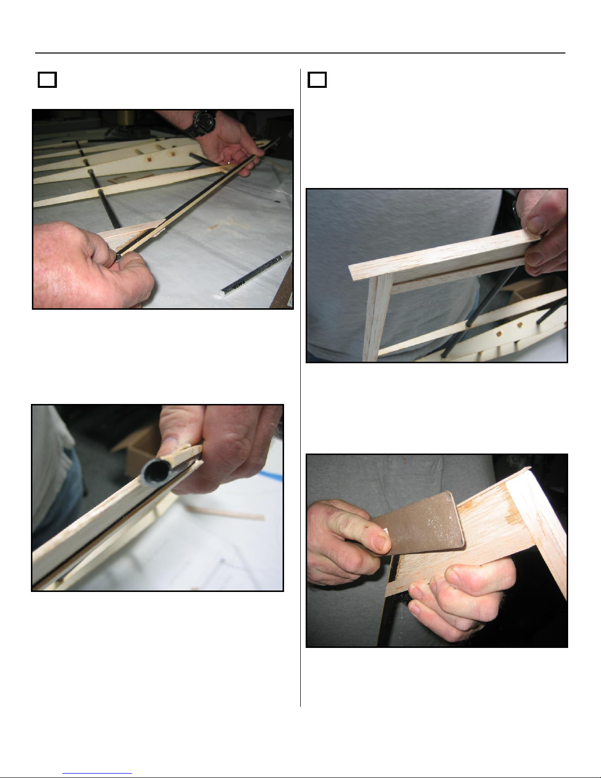
Step 18
Trim the .300 E glass tube flush with the
wing tip (Hack saw, razor saw,9+ or band
saw works well for this; a fine file will also do
the job).
After cutting off the extra tubing from both
L.E. tubes, sand the ends down flush to the
1/4”x1-1/2” elevon stock / balsa wing
tips.
18
Section 1: Framing of the Airframe – Cont.
Step 19
Now separate the unglued portions of the
cap strips at the ends of the T.E. assembly.
Next, place a small piece of balsa stock or a
pencil in between the cap strip and the ¼” x
3/8” T.E. stock to keep the cap strip
elevated. Sand the trailing edge to match
the taper of the wing tip balsa stock. Repeat
the sanding and shaping of the T.E. for both
top and bottom of the T.E assembly on both
sides of the airframe.
When you have finished shaping both sides
of the T.E., glue the cap strips down to the
tapered T.E assembly on both sides of the
airframe.
Your cap strips and trailing edge should look
like the photo below when completed.
19
Section 1: Framing of the Airframe – Cont.
Step 20
Apply cap strips to both top and bottom of the
#3 ribs on both sides of the airframe.
Trim the cap strip with a hobby knife or
scissors to match the angle of the L.E. tube.
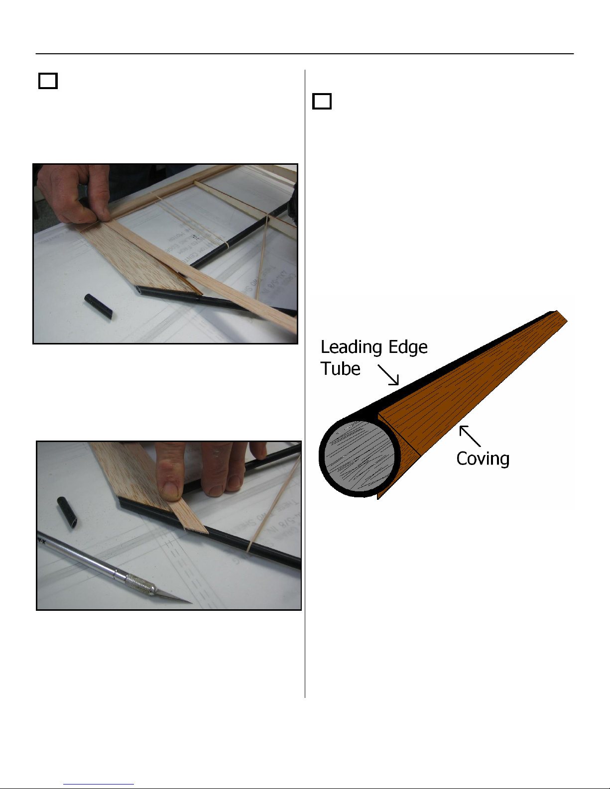
Step 21
Next, locate the leading edge hardwood
coving stock and apply one piece to each of
leading edge tubes with thick CA. Start at
the motor mount and apply rearward. Make
sure to leave a little at the motor mount so
you can cut and sand to shape later.
Note: Take care to apply the coving as strait
as you can on the L.E. tubes.
20
Section 1: Framing of the Airframe – Cont.
Step 21 – Cont.
Cut each piece of coving stock flush with the
tip of the L.E. tubes and the motor mount,
then sand lightly.
Step 22
Now cap strip the outer edge of both the
balsa wing tips from the L.E tubes back to
the T.E. Leave a little extra at both ends
for shaping.
When dry, sand down the end cap strip so it
tapers from the L.E. tube back to the T.E
assembly.
This manual suits for next models
1
Table of contents


