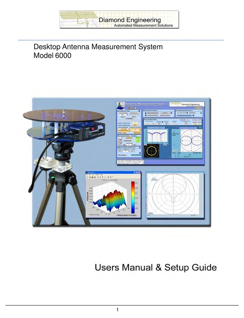
Diamond Engineering DAMS 000 Series User manual

DAMS - Desktop Antenna Measurement System
x000, x100, and x250 Series
Users Manual & Setup Guide


Congratulations on your purchase!
Diamond Engineering’s Desktop Antenna Measurement System has been designed to aid in the
testing and development of small to medium sized antennas. Using our state of the art software, this
system enables you to make many different types of measurements with complete user-denable
conguration settings. The “Advanced Processing” features enable you to not only plot 3D graphs
of the measurements, but also to save and recall those measurements for future use or comparison.
Using the “Group Delay” function, you can calculate the exact distance to the test Antenna, identify
multi-path rays, and eliminate the need for other measuring devices. Our software also allows you
to export your data to a 3rd party application or spreadsheet.
This manual will fully assist you with the assembling and conguring as well as teach you how
to utilize the many features of your Desktop Antenna Measurement System. To achieve the full
functionality of the rotator system, it’s expected the user has some working knowledge about the
concepts and theories involved in microwaves and antenna design development.
We cannot emphasize the importance of fully reading and understanding this manual enough
before actually using the equipment, as to avoid damaging the unit and/or possibly voiding your
warranty.
Best regards,
The Diamond Engineering Team

COPYRIGHT © 2022 Diamond Engineering Inc.
All parts of this publication (including all photographs, illustrations and software) are protected under international
copyright laws and all rights are reserved. This manual may not be reproduced without the express written consent
of Diamond Engineering, nor any of the material contained herein. Diamond Engineering makes no representations of
warranties or statements of tness for any particular purpose. Furthermore, Diamond Engineering reserves the right to
revise this publication or to make changes to the content herein free of obligation to notify any person of such version
changes or updates.
Trademark Acknowledgements:
IBM®, VGA® and ps/2® are registered trademarks of International Business Machines
AMD® is a registered trademark of Advanced Micro Devices Incorporated
Intel®, Pentium III® and Pentium 4® are registered trademarks of Intel Corporation
Microsoft®, Ofce®, Excel®, Windows® are registered trademarks of Microsoft Corporation
VEE®, VEE Runtime®, and Agilent® are registered trademarks of Keysight Corporation
HP® and HPIB® are registered trademarks of the Hewlett Packard Company
Anritsu®, Scorpion® and Lightning®, Shockline® and Vectorstar® are registered trademarks of the Anritsu Corpo-
ration
Labview® is a registered trademark of the National Instruments Corporation
MatLAB® is a registered trademark of Mathworks

Table of Contents
System Overview...........................................................................................................................................................3
Key Features ..............................................................................................................................................................................................................................4
System Requirements ............................................................................................................................................................................................................5
Supported Instruments.........................................................................................................................................................................................................5
Platform Controller Unit .......................................................................................................................................................................................................6
x000 Series Assembly, Installation & Conguration.................................................................................................7
Package Contents....................................................................................................................................................................................................................8
Assembly & Installation (Non-FSM) ................................................................................................................................................................................9
Attaching Optional Thrust Plate........................................................................................................................................................................................10
Assembly & Installation (with FSM-5) ............................................................................................................................................................................11
Attaching the Cables..............................................................................................................................................................................................................12
Software Installation & Conguration ............................................................................................................................................................................13
Controller Setup & USB Driver Installation...................................................................................................................................................................14
Unit Calibration & Positioner Verication (non-FSM) .............................................................................................................................................15
x000 Series Plate Drawing....................................................................................................................................................................................................16
x100 Series Assembly, Installation & Conguration.................................................................................................17
Package Contents....................................................................................................................................................................................................................18
Tripod & Positioner Assembly............................................................................................................................................................................................19
Attaching the Cables..............................................................................................................................................................................................................20
Using the DAMS x100 Positioner ......................................................................................................................................................................................21
x100 Legacy Positioner & Tripod Specications .........................................................................................................................................................22
x100B Positioner & Tripod Specications (2021 and later).....................................................................................................................................23
Positioner Troubleshooting .................................................................................................................................................................................................24
Software Installation & Conguration ............................................................................................................................................................................25
USB Driver Installation & Conguration ........................................................................................................................................................................26
Unit Calibration & Positioner Verication......................................................................................................................................................................27
x100B Plate and Hub Drawings .........................................................................................................................................................................................28
x250 Series Assembly, Installation & Conguration.................................................................................................29
Package Contents....................................................................................................................................................................................................................30
Tripod & Positioner Assembly............................................................................................................................................................................................31
Attaching the Cables..............................................................................................................................................................................................................32
Using the x250 Positioner ....................................................................................................................................................................................................33
x250 Positioner & Tripod Specications.........................................................................................................................................................................34
x250 Thrust Plate / Mounting Plate Drawing...............................................................................................................................................................35
Positioner Troubleshooting .................................................................................................................................................................................................36
Software Installation & Conguration ............................................................................................................................................................................37
USB Driver Installation & Conguration ........................................................................................................................................................................38
Unit Calibration & Positioner Verication......................................................................................................................................................................39
Troubleshooting & Service ..........................................................................................................................................41
General System Troubleshooting......................................................................................................................................................................................42
Warranty, Replacement Parts & Contact Information...............................................................................................................................................43


3
System Overview
Key Features
5000, 6000 and 7000 Models

4
System Overview
Key Features
Light Weight
Platform is made of high quality, light weight Acrylic
material for easy portability.
Easy USB Connectivity
Unit easily connects to the computer using a
standard USB cable.
User Friendly Software
Our software has been designed to be understood
easily to ensure the shortest time to successful
antenna measurement.
High Quality Components
The antenna measurement platform is built mostly
with non-metallic, custom machined parts.
Widely Compatible
Our software supports a wide range of network
analyzers and instruments that use the GPIB /
488.1/2 and SCPI methods of communication. TCP/
IP and USB is supported on some instruments.
Phase/Angle Measurement
DAMS can measure any vector S-parameter over
a specied frequency range, at each measurement
point, using a VNA.
Dual-Axis Movement
360 degrees of horizontal motion at 1/8th degree
per measurement and +/- 45 degrees vertical
movement angle at 1 degree per step.
DC to 8, 18, 40 GHz. Measurement Ranges
Our wide frequency range allows for a diversied
gamut of compatible antennas. (model dependent)
Rotary SMA Joint
Our high-performance rotary joint enables accurate
measurements without jeopardizing signal integrity.
Advanced Data Processing Features
Designed for post measurement
processing you can perform a range of
functions such as:
• 3D visualization for all frequencies
and angles
• Azimuth and elevation plots for true
3D data modeling
• Save / recall data sets from RAM or
local disk
• Group delay (distance calculation)
• Excel-based reports with data
• Efciency, radiation resistance, and
AUT loss
• 4-trace 2D-plots
• Spherical 3D-plots
• Gain plots
• Simultaneously manipulate 4
different data sets
• Map over 50,000 measurement
points into a single 3D-chart
• Reference antenna import feature
• 3-point gain substitution, and path
loss correction methods
• Path loss calculator
• Calculator for modifying
measurement results and comparing
antennas
• Exports data to spreadsheet or 3rd
part application (such as MatLAB)
• Dipole Link Simulator allows creation
of simulated dipole antennas

5System Overview
NOTE: For the most updated list of supported instruments, please visit:
https://www.DiamondEng.net/supported-instruments/
Supported Instruments
If you do not see your instrument on our list, please contact us. It does not necessarily mean it is not supported.
• AMD / Intel (Core i5 or better is recommended)
• 4 GB RAM (minimum)
• 3 GB hard disk space
• 1 available USB port
• 1024 x 768 display resolution (minimum)
• Keyboard and mouse
• Compatible Network Analyzer or Power Meter/Spectrum Analyzer and Signal Generator
• PCI, USB or PC Card based name brand GPIB adapter (OR Ethernet if supported)
• Printer (if printing measured antenna plots)
System Requirements
VECTOR NETWORK ANALYZERS
ADVANTEST R376x Series
Agilent 507x Series
Agilent 836x Series PNA’s
Agilent 836x Series PNA’s
Agilent (HP) 8510x Series
Agilent (HP) 8714 Series
Agilent (HP) 8720 Series
Agilent (HP) 8753 Series
Agilent (HP) 8757 Series
Agilent FieldFox Series
Agilent N5320A Series PNA’s
Anritsu 46xx Series Analyzers (VectorStar)
Anritsu 46xx Series Analyzers (ShockLine)
Anritsu 46xx Series Analyzers (Scorpion)
Anritsu 37xx Series Analyzers (Lightning)
Anritsu MS20xx VNA Master Series
Copper Mountain S2 / S4 VNAs
Planar TR1300 Series
Planar S5048 Series
Rohde & Schwarz ZVx Series
Rohde & Schwarz ZND Series
Rohde & Schwarz ZNB Series
Tektronix TTR500 Series
SIGNAL GENERATORS
HP 83650 Series
HP 8350 Series
Agilent N9310A Series
SMP Series
Anritsu MG36xx Series
Anritsu MG69xx Series
Rohde & Schwarz SML Series
Rohde & Schwarz SMP Series
Rohde & Schwarz SMU Series
POWER METERS
Elva DPM-10
HP436A
HP437B
Anritsu ML2438A
SPECTRUM ANALYZERS
HP8565 Series
Rohde & Schwarz FSL Series
Anritsu MS27xx Series
Anritsu MT82xx Series
OTHER / MISC
Agilent N51xx Series
Anritsu MT8860C
Anritsu S820E
Quanset QM2010 Synth

6
System Overview
Overview
The USB Platform Controller unit is an extremely accurate microprocessor-based stepper
controller. Movement signals are sent from the measurement PC to the controller unit
where precision stepping sequences are generated. A development kit is included which
enables you to write your own custom software to control the platform.
Front View
Top View
Platform Controller Unit

7
x000 Series Assembly, Installation & Conguration
DAMS x000 Series
Instructions for assembly, installation and software conguration

8
x000 Installation & Conguration
Main Components
Use the checklist below to verify all pieces are present and undamaged:
Package Contents
1. Positioner Platform
2. Tripod
3. Vertical assembly
4. Vertical spacer
5. Vertical actuator rod
6. 90 degree pivot **
7. USB Platform Controller
8. Hex wrench tools (SAE and metric)
9. 110/220v power supply w/ AC cord
10. USB cable
11. Laser alignment tool **
12. Two 10’ ultra-low-loss cables *
(SMA male-to-male)
13. Platform control cables
14. Digital inclinometer **
* DAMS 5000 includes low-loss cables
** Discontinued (replaced by FSM)

9x000 Installation & Conguration
Introduction
BEFORE YOU BEGIN: Unpack ALL items and ensure there are no damaged or missing parts.
NOTE: The x000 Series is designed for non-FSM measurements using elevation motor.
Vertical Assembly
1. Unfold tripod and extend the top half-way, then secure the height adjustment. (Fig. 1)
2. Take the grey vertical spacer and snap it onto the very top of the tripod neck. (Fig. 2)
IMPORTANT: Without this piece, your unit will not make accurate vertical measurements.
3. Attach the vertical assembly onto the top of the tripod using the included hex wrench so the top
edge of the vertical assembly is touching the bottom edge of the vertical spacer. (Fig. 3)
Fig. 1 Fig. 2 Fig. 3
Extend tripod Attach vertical spacer
Attach vertical assembly
ensuring vertical actuator rod
does not hit tripod legs as it
moves down
(Continues on next page...)
Assembly & Installation (Non-FSM)

10
x000 Installation & Conguration
Attaching Optional Thrust Plate
1. Ensure the azimuth setting on the
tripod is unlocked.
2. Place the tripod head in a horizontal
position and tighten the locking screw.
3. Align the colored tape on the platform
with the tape on the tripod head and
insert the platform into the head at a 30°
angle. The head will automatically lock
the platform into position.
4. Loosen the tilt lock screw (see Img. 2)
allowing the platform to tilt. Connect the
vertical actuator rod to the platform and
tighten the locknut while holding the hex
shaft using a wrench, ensuring the rod does
not disconnect.
Instructions
Applies to acrylic and aluminum models only.
The thrust plate attaches using the four 10-32x1/4”
screws. Do not overtighten screws. If using your own
screws, be careful not to hit the metal bearing below.

11 x000 Installation & Conguration
Hardware Setup
1. Setup the tripod and extend the neck upwards about 14”.
2. Carefully thread the DAMS positioner onto the tripod.
3. Remove 2 of the 4 thrust plate screws to make room for the FSM mount.
4. Attach the FSM to the top of the DAMS positioner using the included screws as shown in
the attached pictures. The mount is adjustable to allow you to “phase center” the antenna
on the Elevation/Vertical Axis.
5. Connect the cables as shown in the photos above.
NOTE: The support struts shown in the photo are not required. We’ve since updated
with a thicker bottom plate to minimize/eliminate exing.
Software Setup
Click “Congure Positioner” and ensure USB/Serial is selected. Place a check-mark in the FSM
box. Press save, then “restart with default extents” When you restart the software, you will see
the updated positioner picture.
Assembly & Installation (with FSM-5)
IMPORTANT: For FSM-10 installation, please refer to the separate FSM-10 installation manual.

12
x000 Installation & Conguration
Cable Checklist
You should have received the following ve cables with your DAMS System:
Two (2) 10-foot RF Cables SMA/2.92mm/2.4mm/ or V 1.85mm cables (or optional 20-
foot cables)
One (1) USB cable (USB to Micro-USB)
Two (2) 6-meter platform control cables
Cable Connections
NOTE: For FSM-5 connections, see photo on Page 11.
Step 1 Connect USB cable to Platform Controller but DO NOT connect to PC.
Step 2 Connect the power supply wire to the Platform Controller.
Step 3 Connect one end of calibrated SMA cable to bottom of platform.
Step 4 Attach other end of SMA cable to VNA.
CAUTION: USE CARE! Damaged cables will compromise results!
Step 5 Connect straight end of the yellow cable with the black band on the
connector to the “Horizontal” port on Platform Controller and
non-banded cable to “vertical” port.
Step 6 Connect other ends of yellow cables to platform. The banded rightangle
connector connects to turntable, and the non-banded connector
connects to vertical actuator.
Attaching the Cables

13 x000 Installation & Conguration
Software Installation & Conguration
Software Installation
IMPORTANT: Administrator privileges are required to install software.
1. Place CD in CD-ROM or Insert Flash Drive, Navigate to drive and launch setup.exe
2. Click Next/OK through all setup screens.
3. Agilent Runtime and I/O libraries Setup will launch.
Windows 10 Users: you will receive an error that the operating system is not
supported - ignore this error.
4. To verify installation is complete click Start Menu → Programs and ensure the
folders below are present. If so, you may launch Antenna Measurement Studio.
- Agilent Vee Pro Runtime 9.3
- Agilent I/O Libraries
- DAMS
NOTE: If any folders are missing, an installation error occurred. Manually install
components by following instructions below.
Post Installation Instructions
A few extra steps are REQUIRED after the software has been installed
Microsoft Excel Open Excel, go to File → Options and set the default number of
sheets to 3
Matlab 3D Plots Go to C:\Program Files (x86)\Agilent\Vee Pro Runtime 9.3
and right click on veerun.exe. Select the compatibility tab and
select “Run as Administrator”
Entering Your License Key
1. In main screen of DAMS software, at the top of the screen, Under “DEMO LICENSE”,
press “system options” and select LICENSE INFO (not simulator license)
2. Enter the license key located on the CD holder or on the front or back of your users
manual Press “Verify and Save”.
3. Key has been veried should appear. Click “QUIT” and restart the
software to update the license.
License Problems?
E-mail us at Suppor[email protected] or call (530) 626-3857 Monday - Friday, 9:00
A.M. to 5:00 P.M. (PST).

14
x000 Installation & Conguration
Controller Setup & USB Driver Installation
Connecting Controller and Installing USB Drivers -(USB / USB-RS232)
1. Connect DAMS Platform Controller to computer via USB Cable. A window should
appear indicating a new device has been found.
IMPORTANT: When possible, always allow Windows to check for updated driver.
2. If Windows cannot nd the driver, Check the box labelled “Search Manually” then
click “Next”.
3. Select c:\DAMS\driver (if windows does not accept this driver go to
http://www.ftdichip.com and download the latest VCP drivers.)
4. A new window should pop up indicating another device has been found. Allow
Windows to search for an updated driver if you did before. If not, repeat these
steps.
Conguring DAMS Software for x000 Series Positioners
1. Start the DAMS software
2. Click the “Positioner Settings” button
3. Select the USB/Serial option in the upper right from the “Select Controller” pull
down. Click the “Find” button, which should nd your controller (NOTE: the
controller must be on a COM port lower than COM8. If it is not, please congure
the USB/Serial adapter via Control Panel → Device Manager → Ports → COM & LPT.)
4. Set “Motor Res” to .1125 and gear ratio to 14.4 on both AZ and EL elds.
5. The USB controller conguration is now complete. If no controller is found, follow
the troubleshooting instructions below. (NOTE: the COM port must me 9 or lower
for the software to communicate with the controller, this can be changed in
device manager)
6. Press “SAVE” button, followed by “QUIT’ to save changes. Restart software.
Troubleshooting
1. Check all connections between Controller and PC
2. Click Start → Control Panel → System → Hardware Tab → Device Manager
3. Expand section labeled Ports Com&LPT. DAMS Platform controller should be
listed with an associated COM Port. If no controller is listed, re-install the driver.
Please contact us if you need any assistance.

15 x000 Installation & Conguration
Calibrating Vertical Movement to Zero Degrees
IMPORTANT: For the software to move the platform correctly on the vertical
axis you must have the platform at zero degrees when starting
the DAMS Software, or the platform must match the vertical
position shown in the software before moving vertically.
IF THE PLATFORM ANGLE AND SOFTWARE ANGLE DO NOT MATCH:
Use the Jog +/- pull-downs to move the platform to the level position. Once you have
reached the desired position, press “ZERO POSITIONER” to set the current physical
position as “0,0”.
NOTE: If you exit the software without returning to zero, you must follow the
above instructions to once again re-set the positioner to zero degrees.
Verifying Positioner Connectivity and Operation
These steps will assist you with verifying the x000 Series positioner’s operation with the
DAMS software. All steps for installing and conguring the software and connecting
cables should be completed before performing the following steps.
1. Ensure power supply is plugged in and start the DAMS Software.
2. Elevation / Vertical Movement Test
Select -45 from “El jog to” (See image below) pull-down - positioner should tilt
45 degrees towards reference antenna. Select +45 from “El jog to” pull-down and
positioner should tilt all the way to +45 degrees.
3. Azimuth / Horizontal Movement Test
Select 180 from “Az jog to” pull-down. Positioner should rotate 180 degrees of
reference antenna. Select 360 from “Az jog to” pull-down and positioner should
nish the rotation to 360 degrees. (See image below)
4. Resetting to 0, 0 Degrees
After completing the tests, click to clear all position settings and
move the positioner to 0 degrees azimuth and 0 degrees elevation.
Testing and Calibration Complete
Proceed to the Antenna Measurement Studio
Installation chapter to complete the installation
and begin making measurements.
Unit Calibration & Positioner Verication (non-FSM)

x000 Series Plate Drawing
Plate Drawing
Use the drawing below to help design xtures to mount on your DAMS system.
This manual suits for next models
2
Table of contents
Other Diamond Engineering Measuring Instrument manuals
Popular Measuring Instrument manuals by other brands
Gentec-E
Gentec-E TUNER user manual
Tektronix
Tektronix Keithley 2601B-PULSE user manual
Ellisys
Ellisys USB Explorer 200 Getting started guide

Dr.Thiedig
Dr.Thiedig Digox 601 sodium operating instructions
TSI Instruments
TSI Instruments 4040 Operation and service manual

VOLTCRAFT
VOLTCRAFT DO-400 operating manual
