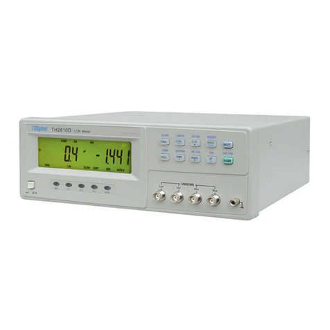
Tonghui Electronics TH1991 User manual

Version History:
This manual will be continuously improved to facilitate the use.
Due to possible errors or omissions in the manual, improvement and refinement of instrument
functions, technical updates and software upgrades, the manual will be adjusted and revised
accordingly.
Please pay attention to the software version and manual version you are using.
First Edition
June 22nd, 2022
Statement: The performance, functions, software, structure, appearance, accessories, packaging,
and instructions of this product may be improved and enhanced by the Company without prior
notice! If it causes any doubt, please contact our company.

TH1991/1992 User Manual V1.1 Contents
Table of Contents
Chapter 1 Overview......................................................................................................................1
1.1 Introduction .................................................................................................................................1
1.2 General Specifications.................................................................................................................1
1.2.1 Power Supply .......................................................................................................................1
1.2.2 Environment / Temperature / Humidity / Altitude ...............................................................2
1.2.3 Warm-up...............................................................................................................................2
1.2.4 Volume and Weight..............................................................................................................2
1.2.5 Attention to the Problem ......................................................................................................2
1.2.6 Safety Standards...................................................................................................................3
1.2.7 Insulation Resistance............................................................................................................3
1.2.8 Dielectric Strength................................................................................................................3
1.2.9 Leakage Current ...................................................................................................................3
1.2.10 Security Certification..........................................................................................................3
Chapter 2 View Description.........................................................................................................1
2.1 Front Panel Description...............................................................................................................1
2.2 Rear Panel Description................................................................................................................2
2.3 Page Summary.............................................................................................................................3
2.3.1 Home Page ...........................................................................................................................3
2.3.2 Config Page..........................................................................................................................4
2.3.3 Quick I/V Page.....................................................................................................................5
2.3.4 Expert Page...........................................................................................................................5
2.3.5 File Page...............................................................................................................................6
2.3.6 System Page .........................................................................................................................6
Chapter 3 Basic Technical Specifications...................................................................................1
3.1 Source/ Measurement Unit ..........................................................................................................1
3.1.1 Measurement Parameters......................................................................................................1
3.1.2 Limit Values/ Compliance....................................................................................................1
3.2 Technical Specifications..............................................................................................................2

TH1991/1992 User Manual V1.1 Contents
3.2.1 Source Specification.............................................................................................................2
3.2.2 Output Specification.............................................................................................................6
3.2.3 Measurement Specifications...............................................................................................12
3.2.4 Trigger and Timing Specifications.....................................................................................16
Chapter 4 Function Instructions.................................................................................................1
4.1 Basic Operation...........................................................................................................................1
4.2 Display Screen Description .........................................................................................................1
4.2.1 Home Show Page .................................................................................................................1
4.2.2 Channel Output Settings.......................................................................................................3
4.2.3 Config Display Page...........................................................................................................18
4.2.4 Quick IV Show Page..........................................................................................................26
4.2.5 Expert Page.........................................................................................................................29
4.2.6 File Page.............................................................................................................................30
4.2.7 System Page .......................................................................................................................30
Chapter 5 Interface Instructions.................................................................................................1
5.1 Measurement Terminals ..............................................................................................................1
5.1.1 Connection Method ..............................................................................................................1
5.1.2 Test Leads and Fixtures........................................................................................................2
5.1.3 Cautions................................................................................................................................2
5.2 Remote Control RS232................................................................................................................3
5.2.1 RS232C Introduction............................................................................................................3
5.2.2 Communication with Computers..........................................................................................4
5.3 Handler Interface Usage Notes....................................................................................................7
5.3.1 Basic Information.................................................................................................................7
5.3.1 Interlocking Circuits.............................................................................................................9
Chapter 6 Command Reference..................................................................................................1
6.1 Command Structure.....................................................................................................................1
6.1.1 Structure Rules .....................................................................................................................1
6.1.2 Multiple Commands Rule.....................................................................................................2
6.1.3 Abbreviation Rules...............................................................................................................3

TH1991/1992 User Manual V1.1 Contents
6.2 Symbol Conventions and Definitions..........................................................................................4
6.2.1 Symbols................................................................................................................................4
6.2.2 Suffix Numbers ....................................................................................................................5
6.2.3 Channel List Parameters.......................................................................................................5
6.3 Data Output Format.....................................................................................................................5
6.4 Command Reference ...................................................................................................................6
6.4.1 DISPlay Subsystem Command.............................................................................................7
6.4.2 FORMat Subsystem Command............................................................................................9
6.4.3 FETCh Subsystem Command ..............................................................................................9
6.4.4 MEASure Subsystem Command........................................................................................13
6.4.5 OUTPut Subsystem Command...........................................................................................15
6.4.6 SENSe Subsystem Command.............................................................................................20
6.4.7 SOURce Subsystem Command..........................................................................................28
6.4.8 SYSTem Subsystem Command..........................................................................................40
6.4.9 TRIGger Subsystem Command..........................................................................................51
6.4.10 Public Command ..............................................................................................................53
6.5 Error...........................................................................................................................................54
Chapter 7 Kitting and Warranty................................................................................................1
7.1 Kits ..............................................................................................................................................1
7.2 Warranty......................................................................................................................................1

TH1991/1992 User Manual V1.1 Chapter 1 Overview
Chapter 1--1
Chapter 1 Overview
Thank you for purchasing and using our products. Before you use this instrument, please first
confirm the matters in the last chapter of the manual "Set and Warranty". If there is any
discrepancy, please contact us as soon as possible to protect your rights and interests.
1.1 Introduction
TH1991/TH1992 is a series of precision source/measure units, referred to as SMU. It offers
touch screen, front panel keys and knobs to apply voltage/current or measure
voltage/current/resistance. The instrument also supports several functions such as sweep output,
pulse output, arbitrary waveform generation, limit test, trace buffer, mathematical expressions,
and graphical printing. Thus, the TH1991 / TH1992 can be DC (constant) voltage/current source,
sweep voltage/current source, pulse generator, arbitrary waveform generator and multimeter.
Model
Number of
Channels
Valid Settings and Measured Values
Minimum Resolution
Maximum
Current
Maximum
Voltage
Source
Measurement
TH1991C
1
1pA,1uV
100fA,100nV
DC: ±1.515A
Pulse: None
±63V
TH1991B
100fA,1uV
10fA,100nV
DC: ±3.03A
Pulse: None
±210V
TH1991A
1pA,1uV
100fA,100nV
DC: ±3.03
Pulse: ±10.5V
TH1991
10fA,100nV
10fA,100nV
TH1992B
100fA,1uV
10fA,100nV
TH1992A
2
1pA,1uV
100fA,100nV
TH1992
10fA,100nA
10fA,100nV
Table 1-1 TH1991 / TH1992 Series Product
1.2 General Specifications
1.2.1 Power Supply
Supply voltage: 90V to 264V
Power frequency: 50Hz/60Hz (1±5%)
Power consumption: <250VA

TH1991/1992 User Manual V1.1 Chapter 1 Overview
Chapter 1--2
1.2.2 Environment / Temperature / Humidity / Altitude
Environment: suitable for indoor equipment use
Operation status:
Temperature: 0℃to +55℃
Humidity: 30% to 80% RH (no condensation)
Altitude: 0~2000m (6561ft)
Storage status:
Temperature: -30℃to +70℃
Humidity: 10% to 90% RH (no condensation)
Altitude: 0~4600m (15092ft)
1.2.3 Warm-up
Warm-up time after power on: ≥ 60 minutes
1.2.4 Volume and Weight
Whole machine size (W*H*D): 235*154*530
Upper frame size (W*H*D): 215*132*490
Weight: 10kg (dual channel) / 8.5kg (single channel)
1.2.5 Attention to the Problem
Please do not use it in adverse environment such as dusty, vibration,
direct sunlight, corrosive gas, etc.
If the instrument is not used for a long time, please store it in the
original packing box or similar box in the ventilated room. The air
should not contain harmful impurities that corrode the instrument and
should be protected from direct sunlight.
This instrument should be used in the low noise environment as
much as possible. If this cannot be avoided, please install the power
filter.
Please make sure the instrument is in a well-ventilated condition with
forced ventilation with air intake at the side and exhaust at the rear of
the instrument to avoid the internal temperature rising and affecting
the accuracy.
Do not switch the instrument on and off frequently to avoid loss of
stored data.

TH1991/1992 User Manual V1.1 Chapter 1 Overview
Chapter 1--3
1.3 Safety Standard
This instrument is a Class I safety instrument
EMC Standard: IEC61326-1/EN61326-1/AS/NZS CISPR 11
1.3.1 Insulation Resistance
The insulation resistance between the power supply terminals and the
housing is not less than 50MΩunder reference operating conditions.
Under hot and humid transportation conditions, the insulation
resistance between the power terminals and the housing is not less
than 2MΩ.
1.3.2 Dielectric Strength
Under reference operating conditions, the power supply terminals
and the housing can withstand the rated voltage of 1.5kV, frequency
of 50Hz AC voltage for 1 minute, no breakdown and flying arc
phenomenon.
1.3.3 Leakage Current
Leakage current is not more than 3.5mA.
1.3.4 Security Certification
CE, cCSAus, C-Tick

TH1991/1992 User Manual V1.1 Chapter 2 View Description
Chapter 2--1
Chapter 2 View Description
The content of this chapter is only a general description; the specific
operation and detailed explanation refer to the corresponding content of
Chapter 4.
2.1 Front Panel Description
Figure 2-1 Front Panel Diagram
USB-A connector: Used to connect USB memory. After
disconnecting the USB memory, wait for 10 seconds and then
connect it again or connect a new memory.
※Note: If the instrument is turned off while the USB memory is being
accessed, the device may be damaged.
CH1/CH2: Used to enable or disable the SMU channel. Disables the
channel if it is in the output state, even if it is in the remote state. 1-
channel models have 1 button; 2-channel models have 2 buttons.
If the channel is enabled, the button will turn yellow.
If the channel is in the high voltage state, the switch will turn red.
Trigger: Starts a single measurement. Stops repeated measurements
if they are being made.
TH1992 Precision Source/Measure Unit
10 fA 2 ch
Sense Sense
LO
±210V
MAX
HI
±250V Force
MAX
CH1 Guard
POWER
CH1
CH2
Trigger
Auto
Local

TH1991/1992 User Manual V1.1 Chapter 2 View Description
Chapter 2--2
Auto: Starts a repeat measurement. Stops repeated measurements if
they are being performed.
Local: If the instrument is in the remote state, return it to the local
state
Line switch: Turns the instrument on and off.
Channel 1 source/measurement terminals: High Force, Low Force,
High Sense, Low Sense, Guard, and Chassis Ground. (See 5.1
Measurement Terminals)
※Note: Do not connect the Guard terminal to any output, including the
common circuit, chassis ground wire, or any other protective
terminal; otherwise this may damage the instrument.
※Note: The maximum current of the chassis ground terminal is 3A DC.
Knob: If the field pointer is in the Parameter Setup page or Setup
box, turn the knob to change the value of the setup parameter. Press
the knob to fix the value and exit the value setting page.
If the field pointer is on the Graph and Roll view pages, turn the
knob to adjust the interval of the display of the axis pages.
2.2 Rear Panel Description
Figure 2-2 Rear Panel Diagram

TH1991/1992 User Manual V1.1 Chapter 2 View Description
Chapter 2--3
Channel 2 source/measurement terminals: For 2-channel models
only, High Force, Low Force, High Sense, Low Sense, Guard, and
Chassis Ground. (See 5.1 Measurement Terminals)
Cooling fan: Forced ventilation to avoid internal temperature rising
and affecting accuracy.
Three-wire power outlet: Voltage is 90V to 264V, and the power
frequency is 50Hz.
Handler connector: DSUB25 pin female connector is used for
general purpose I/O. It can be used for data input/output, trigger
input/output terminals and other functions.
USB-B connector: Used to connect USB memory.
LAN interface connector: Connects to the 10/100 Base-T interface.
Left LED indicates the active status, and the right LED indicates link
integrity.
RS232 connector: Provides a universal communication interface
between the instrument and external devices, all parameter settings,
commands, etc. can be set and obtained by the computer for realizing
remote control without the instrument panel.
2.3 Page Summary
2.3.1 Home Page
Figure 2-3 Home Page
The Home page is the main power-up screen of the instrument and
displays the Dual view. The upper area is for channel 1 and the lower area is

TH1991/1992 User Manual V1.1 Chapter 2 View Description
Chapter 2--4
for channel 2. Each area displays the measurement results, the source, and
the measurement settings. The parameters that can be set are as follows:
Source: Source function, voltage source VOLTs (V) or current
source AMPs (I).
V-range: If the source is the voltage source, this parameter is the
output voltage range.
If the source is the current source, this parameter is the measured
voltage range.
I-range: If the source is the current source, this parameter is the
output current range; if the source is the voltage source, this
parameter is the measured current range.
Output: The source output value.
Limit: Limit (compliance) value.
※Note: Double click on the display area of Channel 1 or Channel 2 to
enter the specific setting with 3 pages of parameters for
different channels. 3 pages can be turned by swiping left and
right on the touch screen.
2.3.2 Config Page
Figure 2-4 Config Page
The Config page is for processing the measurement output data for
filtering, deduction of deviations, mathematical operations, or limit tests.
The parameters that can be set are as follows:
CH1/CH2: Select Channel 1 or Channel 2 for data processing.

TH1991/1992 User Manual V1.1 Chapter 2 View Description
Chapter 2--5
Filter Setup: Filter Setup.
Relative offset: The relative offset setting.
Math Function: Math operation function setting.
Limit tests: Limit test setting.
2.3.3 Quick I/V Page
Figure 2-5 Quick I/V Page
The Quick I/V page mainly displays the Graph and Roll views. The
Graph view shows the graph that plots the results of measurements or
mathematical operations for Channel 1 or Channel 2, and the Roll view
shows the time-domain diagram that plots the measurement data for Channel
1 or Channel 2.
2.3.4 Expert Page
Figure 2-6 Expert Page

TH1991/1992 User Manual V1.1 Chapter 2 View Description
Chapter 2--6
The Expert page is the graphical analysis of semiconductor parameters,
which is the advanced function and contains the following test functions:
Diodes: Diode Testing
FETs: Field Effect Transistor Testing
BJTs: Triode Testing
IGBTs: Insulated Gate Bipolar Transistor Testing
Utility: Universal Testing
2.3.5 File Page
Figure 2-7 File Page
The File page displays a list of files, including file name, file type, file
creation time, and other information. You can store data, copy, and paste
files, rename, and delete files on this page.
2.3.6 System Page

TH1991/1992 User Manual V1.1 Chapter 2 View Description
Chapter 2--7
Figure 2-8 System Page
RS232/GPIB: Serial/GPIB communication setting
Usb device: USB setting
Network: Network setting
Digital I/O: Input/output pin setting
User Setup: User setup
Date Time: Device date and time setting
Update: Update information setting
Tools: System tools setting

TH1991/1992 User Manual V1.1 Chapter 3 Basic technical specifications
Chapter 3--1
Chapter 3 Basic Technical Specifications
3.1 Source/Measurement Unit
Source/Measurement Unit (SMU): can apply voltage or current and
measure current or voltage.
SMU can perform the following operations:
Apply voltage and measure current
Apply current and measure voltage
Apply voltage and measure voltage
Apply current and measure current
Figure 3-1 Display Simplified SMU Circuit Diagram
3.1.1 Measurement Parameters
U: Voltage I: Current
R: Resistance P: Power
The resistance data is specified by Resistance=Vmeas/Imeas.
The power data is specified by Power=Vmeas×Imeas.
In the above equation, Vmeas is the voltage measurement data, Imeas is
the current measurement data.
3.1.2 Limit / Compliance
The TH1991/TH1992 has the compliance function that limits the output
voltage or current to prevent damage to the device under test. When the
SMU applies voltage, the current limit/compliance can be specified. When
the SMU applies current, the voltage limit/compliance can be specified.
When the channel reaches compliance, the channel will act as the

TH1991/1992 User Manual V1.1 Chapter 3 Basic technical specifications
Chapter 3--2
constant voltage source or constant current source. When the compliance is
achieved, the channel will retain the output value. The compliance can be set
by using the same resolution and accuracy as the output current or output
voltage.
※Note: When setting compliance
Minimum compliance value:
Current compliance: 1% of range (in the range 100nA), 1nA (in
the range 10nA).
Voltage compliance: 1% of range.
If the current compliance value is too low, the SMU will take a long
time to stabilize.
If the SMU is unable to force the specified current due to the
following reasons, the SMU will achieve voltage compliance:
Test equipment overcurrent.
Another channel has reached compliance.
The current measurement data of the other channel has reached
the limit of the current measurement range.
3.2 Technical Specifications
This chapter lists the specifications and features of the
TH1991/TH1992 series. The specifications are based on the standards that
test TH1991/TH1992, and the requirements which they conform at the
factory.
3.2.1 Source Specifications
3.2.1.1 Voltage Sources
Measurement
Range
Programming Resolution
Accuracy (gain error
(% of reading) + offset
error)
Noise (peak-
to-peak)
0.1Hz to
10Hza
Maximum
Voltage
(over range)
TH1991C
TH1991B
TH1992B
TH1991A
TH1992A
TH1991
TH1992
±200mV
1uV
1uV
0.1uV
±(0.015%+225uV)
≤10uV
±210mV
±2V
10uV
10uV
1uV
±(0.02% + 350uV)
≤20uV
±2.1V

TH1991/1992 User Manual V1.1 Chapter 3 Basic technical specifications
Chapter 3--3
±20V
100uV
100uV
10uV
±(0.015%+5mV)
≤200uV
±21V
±200Vb
-
1mV
1mV
100uV
±(0.015%+50mV)
≤2mV
±210V
Table 3-1 Voltage Source Specifications
*Note: Superscript a: Additional features
Voltage limit/compliance: Accuracy is the same as the voltage source.
The minimum value is 1% of the range or 20mV of the 200mV range.
Over range: 105% of source range.
Voltage output stabilization time (time required for 0.1% range of
final value under open circuit load conditions): Steps are 10% to 90%
range.
200mV and 2V range: <50us, 20V range: <110us.
200V range: <700us
Noise 10Hz to 20MHz (V source): 50mVrms, 20V range
V source overshoot: <±(0.1%+10mV) Step size is 10% to 90% range,
resistive load.
Voltage source range change overshoot: ≤250mV, 100kΩ load,
20MHz bandwidth.
Superscript b: ±200V does not apply to TH1991C.
3.2.1.2 Current Source
Measurement
Range
Programming Resolution
Accuracy
(gain error
(% of
reading) +
offset error)
Noise
(peak-to-
peak)
0.1Hz to
10Hza
Maximum
Current
(over range)
TH1991C
TH1991B
TH1992B
TH1991A
TH1992A
TH1991
TH1992
±10nAb
-
100fA
-
10fA
±(0.10%+50
pA)
≤2pA
±10.5nA
±100nAb
-
1pA
1pA
100fA
±(0.06%+10
0pA)
≤5pA
±105nA
±1uA
10pA
10pA
1pA
±(0.025%+5
00pA)
≤25pA
±1.05uA
±10uA
100pA
100pA
10pA
±(0.025%+1
.5nA)
≤60pA
±10.5uA

TH1991/1992 User Manual V1.1 Chapter 3 Basic technical specifications
Chapter 3--4
±100uA
1nA
1nA
100pA
±(0.02%+25
nA)
≤3nA
±105uA
±1mA
10nA
10nA
1nA
±(0.02%+20
0nA)
≤6nA
±1.05mA
±10mA
100nA
100nA
10nA
±(0.02%+2.
5uV)
≤200nA
±10.5mA
±100mA
1uA
1uA
100nA
±(0.02%+20
uV)
≤600nA
±105mA
±1A
10uA
10uA
1uA
±(0.03%+1.
5mA)
≤70uA
±1.05A
±1.5A
10uA
10uA
1uA
±(0.05%+3.
5mA)
≤150uA
±1.515A
±3Ad
-
-
100uA
10uA
±(0.4%+7m
A)
-
±3.03A
±10Ad、e
-
-
100uA
10uA
±(0.4%+25
mA)f
-
±10.5A
Table 3-2 Current Source Specifications
※Note:
Superscript a: Additional features
Current limit/compliance: Accuracy is the same as current source,
the minimum value is 1% of the range, or 1nA of the 10nA
range.
Over range: 1.5A and 3A range are 101% of the source range, the
rest is 105% of the source range.
Current output stabilization time: (time required for 0.1% range
of final value under short circuit conditions): Steps are 10% to
90% range.
10nA and 100nA range: <10ms, 1uA range: <500us
10uA and 100uA range: <250us, 1mA to 3A range: <80us
I source overshoot: <±0.1%, the step size is 10% to 90% range,
resistive load.
Current source range change overshoot: ≤250mV/R load, 20MHz
bandwidth.

TH1991/1992 User Manual V1.1 Chapter 3 Basic technical specifications
Chapter 3--5
Superscript b: ±10nA does not apply to TH1991A/C and TH1992A.
Superscript c: ±100nA is not applicable to TH1991C.
Superscript d: ±3A, ±10A do not apply to TH1991B/C and TH1992B.
Superscript e: ±10A range is for pulse mode only, not for DC mode.
Superscript f: Measurement speed: 0.01 PLC.
3.2.1.3 Pulse source
Maximum
Voltage
Maximum
Peak Current
Maximum
Base Current
Maximum
Pulse Width
Maximum
Duty Cycle
DC or Pulse
6V
3.03Aa
303Aa
DC, Infinite
Value
100%
21V
1.515Aa
1.515Aa
DC, Infinite
Value
100%
210V
0.105A
0.105A
DC, Infinite
Value
100%
Pulse Only
6V
10.5A
0.5A
1ms
2.5%
180V
10.5A
50mA
10ms
2.5%
200V
1.515A
50mA
2.5ms
2.5%
Table 3-3 Maximum Pulse Width and Duty Cycle
※Note:
Superscript a: For two channels, the maximum total current for both
channels is limited.
Pulse width definition: Time from 10% leading edge to 90% trailing
edge, as shown in the figure below.
The pulse source is always measured with the fixed range.
Figure 3-2 Pulse Width (10% leading edge to 90% trailing edge)
This manual suits for next models
1
Table of contents
Other Tonghui Electronics Measuring Instrument manuals
Popular Measuring Instrument manuals by other brands
THORLABS
THORLABS VEGA Series operating manual
Rohde & Schwarz
Rohde & Schwarz R&S FSVA quick start guide
HEIDENHAIN
HEIDENHAIN ND 221 manual

Braglia
Braglia 200.302.63 Directions for installation, use and maintenance
Deif
Deif MIB 7000 Installation Instructions and Reference Handbook

Hioki
Hioki 3284 HiTester instruction manual

