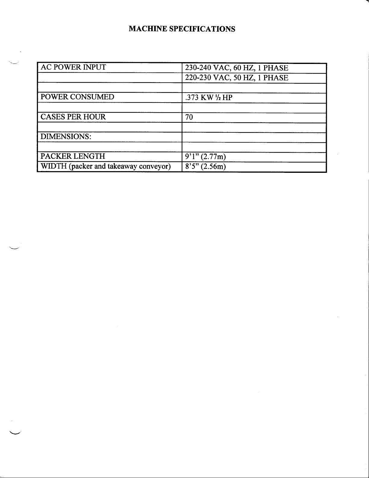
manuals.online logo
Brands
  1. Home
  2. •
  3. Brands
  4. •
  5. Diamond Systems
  6. •
  7. Industrial Equipment
  8. •
  9. Diamond Systems 70 CPH FARMPACKE User manual

Diamond Systems 70 CPH FARMPACKE User manual

70cph FARMPACKER
IMPORTANT – PLEASE READ!
The information provided in this manual has been carefully checked and is
believed to be accurate. However, changes are made periodically, THESE
CHANGES ARE INCORPORATED IN NEWER PUBLICATIONS.
Diamond Systems may improve and/or change products described in this
publication at any time. Due to continuing system improvements, Diamond
Systems is NOT RESPONSIBLE for inaccurate information, which may appear in
the manual.
In no event will Diamond Systems be liable for direct, indirect, special, exemplary,
incidental, or consequential damages resulting from any defect or omission in this
manual. Even if advised of the possibility of such damages.
In the interest of continued product development Diamond Systems reserves the
right to make improvements in this manual and the products it describes at
anytime, without notice or obligation.
For the latest product updates please call Diamond Systems Sales or Service.
MAY, 2001
23400 Haggerty Road, Farmington Hills, Michigan 48335-2635 USA
Office: 248-476-7100 FAX: 248-476-0849
Email: [email protected]
WARNING!
SAFETY AND SERVICING
CLEANING, REPAIRING AND/OR ADJUSTING
DO NOT OPERATE ANY PART OF THE
MACHINE UNLESS ALL GUARDS ARE IN
PLACE.
NEVER service, clean, repair and/or adjust any part of the machine
while the machine is still on and/or in operation.
STOP the machine and lock it out before servicing, cleaning,
repairing, and/or adjusting. If the machine cannot be stopped or
turned off, wait until production for the day is completed. If any
guards are removed for service, cleaning, repairing, and/or adjusting
the machine, replace all guards and secure them before restarting
the machine.
Keep all floors dry and free of broken egg, water, oil, and debris in
traffic area of the processing operation. IF the floor becomes wet it
take whatever steps are necessary to keep the floor dry.
Employees should not operate or service the equipment with loose
clothing or long hair.
Make sure all supervisors and employees
understand the importance of keeping all
guards in place and keeping the floor clean
and dry.
January, 2001
SvsrEMS
70
CPH
FARMPACKER
ForParts
&Service:
United
States.
Tel: 248-476-7274
Fax: 248-476-3617
Spain:
Tel: 34-94-432-9252
Fax: 34-94-433-6734
Malaysia:
Tel:
60-3-5631-4991
Fax:
60-3-5631
-5991
DiamondAutomation
23400HaggertyRoad
FarmingtonHills,
Michigan48335-2635
USA
EMail
- [email protected]
Office 248-476-7100
DirectDial 248-476-7106
+ Ext.
_
Fax 248-476-0849
Service 248-476-7274
www.diamondsystem.com
TABLE OF CONTENTS
I|ACEIIIESPECIFICiAIIONS .. .. . 1
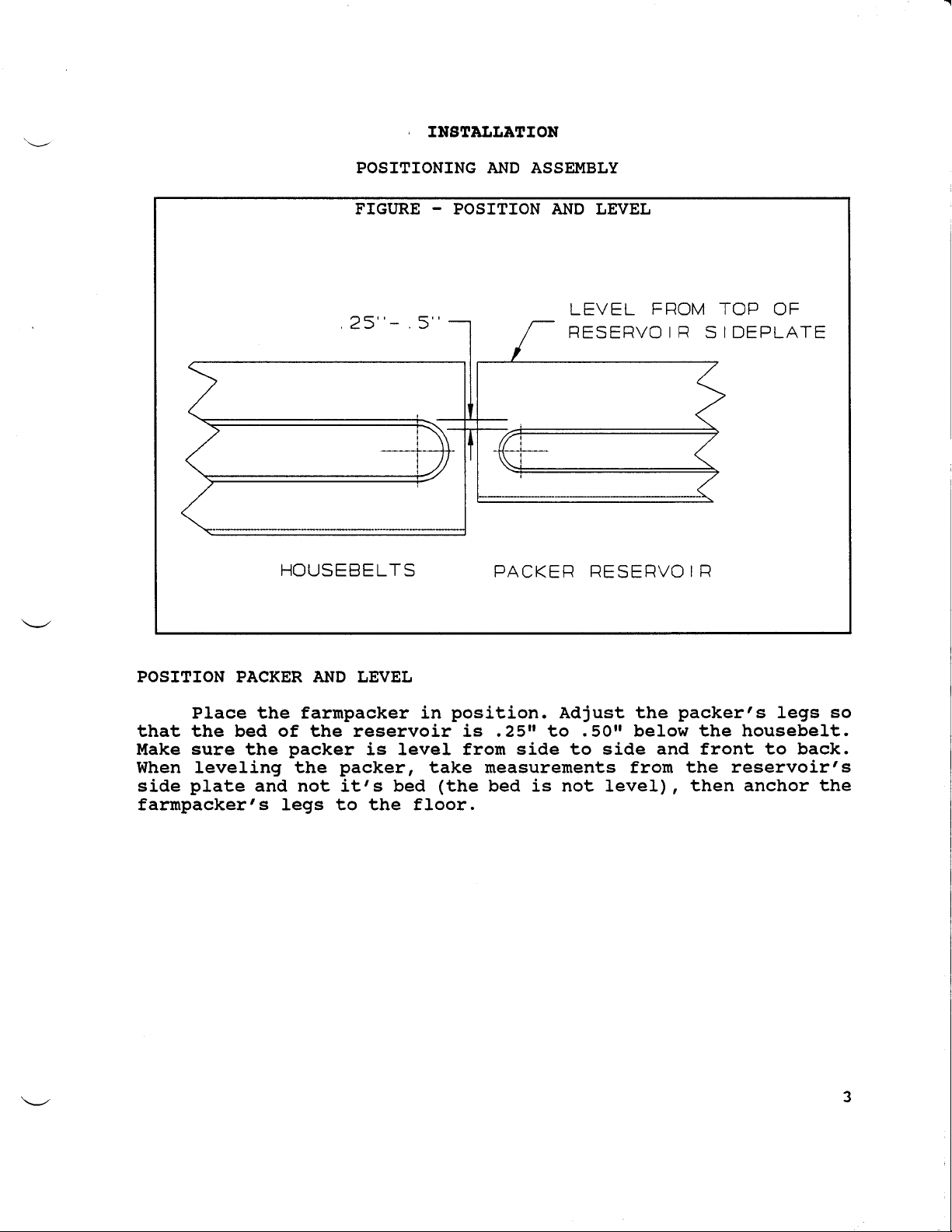
INgraLLtrroil . . 3
POSITIONINGAI{DASSWBLY .... . 3
INSTALL TAIG.AWAY COM/EYOR TO THE RIGHT 4
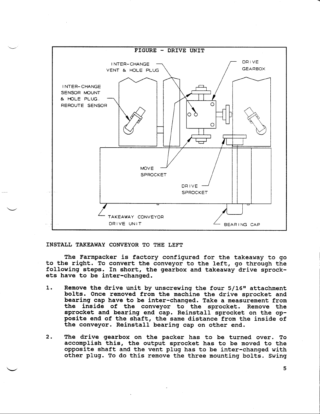
INSTALL TAKE.AWAY COM/EYOR TO THE LEFT O O " " ' 5
ELESIRTCAL HOOKT'P . 7
AC INPIIT . 7
HOUSEBELTS(ELECTRICAL)....o. I
AC HOOKT'P DIAGRAIT{ . 9
FERUPAC.trER CIJEAITIT{G
FERUPAC.trEI, IJUBRICAIION
OPERA!ION
CONTROL PAI.IEL FI'NCTIONS
PACKER OPER.ATION
aDitugruENr
TIITIE DEI,AY ADJUST!{ENT
DENESTERADWST!{ENT
ADJT'ST THE JAW CENTERSTO FI,AT.
ADJUST THE JAW OPENTNG. O ' ' '
ADJUST THE CI,AI.TPPLATES TO THE STACK OF FI,ATS.
SENSORADJUST!{ENT
DENESTERSTART SENSOR
DENESTER STOP SENSOR
10
10
11
11
13
15
15
16
16
L7
18
20
20
20
CYCLE STOP SENSOR . 2L
MOTOR CONTROL ADJUSTI{ENT 22
HEJADTIMING ADJUSTMENT . 23
CI,AII{SHELL ADJUS$IENTS . 24
CI,AI{SHELL RELEASE ADJUSTMENTS . 25
LONG AI.ID SHORT ADVANCE ADJUSTMENTS . 27
TROI'BIJESEOOrING . 29
ELECTRICAL . 29
P.C.B. LIGHT . 29
PACKER UALFT'NCTIONS 30
REFEREXCE / ELECARICAL, DRtrINcs . 35
UISCELI,ANEOUS DRAWINGS . 35
ELECTRICAL DEVICE LOCATION 35
TB-2 I.{IRING DTAGR,N! 35
scHnMATrcs . 37
SYSTEIT{ FLOWCTTART 39
ELECTRICAL BOX ASSEMBLY 41
RETERETSCE
/ UECEAXIeAL, DRATINGS . 42
JAPAI{ESE DENESTER
LITT PI.ATE ASSEMBLY . 42
PKSASSEI{BLY .. 43
RESERVOIRASSEIIBLY . 44
FARMPACKER
BASE ASSEMBLY . . 45
PUSHERCHAINASSEIIBLY .. . 45
DENESTERSIDE PI,ATE ASSEITTBLY 47
DENESTER
LIFT PI.ATE ASSEMBLY . . 48
FARUPACKERGUARDS .. .. . 49
FARUPACKER
HEAD ASSEUBLY 50
CI,AUSHELL ASSB.TBLY . 54
DRIVE TRAIN ASSE}IBLY 55
Lt
MACHINE SPECIFICATIONS
AC POWERINPUT 230.240
VAC, 60HZ, I PHASE
220.230
VAC, 50
HZ, 1PHASE
POWER
CONSUMED .373KW |/I
HP
CASESPERHOUR 70
DIMENSIONS:
PACKERLENGTH 9'1"
(2.77m)
WIDTH (packer
andtakeawayconveyor) 8'5"
(2.56m)
INSTAI.LATION
POSITIONING AND ASSEMBLY
FIGURE - POSITION AND LEVEL
LEVEL FROM
RESERVOI
R STOP OF
I
DEPLATE
HOUSEBELTS PACKER RESERVO
IR
POSITION PACKERAND LEVEL
Place the farmpacker in position. Adjust the packer's legs so
that the bed of the reservoir is .25rr to .50tt below the housebelt.
Make sure the packer is level from side to side and front to back.
When leveling the packer, take measurements from the reservoi.rts
side plate and not it's bed (the bed is not leveI), then anchor the
farmpacker's legs to the floor.
FIGURE - TAKEAWAY CONVEYOR
TAKEAWAY BELT
I
DLER ADJUST
TAKEAWAY CONVEYOR
D
IRECTI
ON OF BELT
DRIVEUNIT
4 PLACES
AND DR
IVE
ATTACH
SECT
I
ONTA
KEAWAY
2 PLACES
ATTA
C
HMENT
CHAIN TAKE UP
TNSTALL TAKEAWAY
CONVEYOR
TO THE RIGHT (FACTORYCONFIGURED)
1. fnstall takeaway conveyor and attach it to the drive unit with
two 5/15tt bolts with lockwasher and nuts.
2. Loosen takeaway belt id1er. Thread belt through conveyor as
shown above, naking sure belt direction is correct (see arrows
on underside of belt). Insert connecting pin in belt. Move
idler to the top of the slot and retighten.
3. Mount electrical box onto rrCrr
brackets on conveyor.
4. Adjust takeaway height so that it is comfortable to operator.
Anchor packer legs. Adjust electrical box.
5. Install guides fron packer to takeaway conveyor. NOTE: Mount
guides to outside of packer rails. A catch point is created
when they are mounted to the inside.
6. Proceed to Electrical Hookup.
FIGURE - DRIVE UNIT
INTER-CHANGE
VENT & HOLE PLUG
I
NTER-CHANGE
SENSOR MOUNT
& HOLE PLUG.
FIEROUTE SENSOFI
TAKEAWAY CONVEYOFI
DRIVE UNIT BEAFI
ING CAP
INSTALL TAKEAWAY
CONVEYOR
TO THE LEFT
The Farmpacker is factory configured for the takeaway to go
to the right. To convert the conveyor to the left, go through the
following steps. In short, the gearbox and takeaway drive sprock-
ets have to be inter-changed.
1. Renove the drive unit by unscrewing the four 5/I6n attachrnent
bolts. Once removed from tbe machine the drive sprocket and
bearing cap have to be inter-changed. Take a measurement frour
the inside of the conveyor to the sprocket. Remove the
sprocket and bearing end cap. Reinstall sprocket on the op-
posite end of the shaft, the same distance fron the inside of
the conveyor. Reinstall bearing cap on other end.
2. The drive gearbox on the packer has to be turned over. To
acconplish this, the output sprocket has to be moved to the
opposite shaft and the vent plug has to be inter-changed with
other plug. To do this remove the three mounting bolts. Swing
I
gearbox out fron chain and turn on side. Replace the vent plug
with the plug on opposite side. Take a measurernent fron the
gearbox to the sprocket. Remove and then reinstall sprocket
on opposite shaft the same distance from the gearbox.
Reinstall gearbox in packer with the output sprocket facing
out.
3. Reinstall drive unit onto packer with (4) 5l1-6n bolts.
4. Unscrew rfAnti Jamrr sensor and reroute to other side. Inter-
change sensor bracket with hole plug. Remount sensor naking
sure it is aligned to the center of the reflector.
5. Install takeaway and attach to drive unit with (2') 5/L6n
bolts with lockwasher and nuts.
6. Remove The Electrical lev ttQr mounting brackets from takea-
way conveyor and reinstall on opposite side.
7. Mount electrical box onto [Crf brackets on conveyor.
8. Loosen takeaway belt idler. Thread belt through and install
connecting pin. Move idler to the top of the slot and retight-
en.
Adjust takeaway height so that it is comfortable to operator.
Anchor packer legs. Adjust electrical box so it is level.
10. Reurove reflector from outside guide and reinstall on opposite
end. Install guides onto packer and takeaway conveyor. NoTE:
Install guides to outside of packer rails. A catch point is
created when they are mounted to the inside.
11. Proceed to electrical hookup.
9.
ELECTRICAL HOOKUP
AC INPUT
This rnachine is factory wired to the voltage,
frequency (IlZ.) shown on the machine naneplate. The
located on the back cover of the control box.
phase, and
nameplate is
FIGURE - NAMEPI,ATE
VCLTAGE
FREGUENCY
FULL LOAD C
OVERCURRENT PROTECT
I
ON
URRENT
PROV
I
DED AT
NAMEPLATE
|-] AMPS
MACHINE SUPPLY TERM
INALS
No 36348
tl
TIGURE - AC POWER & HOUSEBELTS
POWER HOOK-UP D
I
AGRAM
UINE 'O XACXIf,E {AMEPLAT€ VOLTAGE
23O-2aO vac. 8o HZ. 1PH- 3 vtREs
22O-21O vaC, 5O FZ. lFH. 3 vtFEs
TB3
HOOX-UP OTAGFAX
HOUSE I€L'
xoTog
L1
L2
ttl5
WARN
ING
DO NOT UA(E AXY
AOJUSTMEilTS ON
IHE UOTOF COf,tROL
f ITHOUT CONSULT I
NG
OIAUONO OI GLSE THE
rannattY trLL 8G
vo I
oEo
o€caL . 3tr2900
fnside the control box back cover there is a terminal strip
and an AC Power Hook-up Diagram decal. connect power to TB-3.
HOUSEBELTS(ELECTRICALI
Connect housebelt rnotor or housebelt control relay to ter-
ninals T83-6 and TB3-7. These terminals are connected to the
normally open contacts of a reray that are rated for Ll2 Hp at 125
VAC or 1 HP at 250 VAC. Do NoT ExcEED THESERATINGS!
FIGTIRE - AC HOOKUP
o
o
z
;
al
ur<
VF
oo
<z
rL()
ou
U
OJ
@ul
"t
s!
I Ic
!
to.
;<F<
, t;i
! ::.
o-.
-oc
1..
oi
-OO
F'F
oEl
oS'
is!
:0
I:r
9^^
I'l
r:l
iv-
it""
o,
:
,
n
o
o
F.
c|
FAN'IIPACXERCIJEAITIITG
A11 of the items listed below should be perforrned everyday.
1. Renove and clean all drip trays.
2. Wipe down the egg reservoir with a clean danp cloth.
3. Wipe ALL of the white end alignment rollers with a danp cloth.
4. Conpressed air may be used on a1l areas of the packer.
5. NEVER spray water on any area of the packer.
FERITPICXER IJUBRICATION
1. Use 30 weight motor oil on all chains.
2. AII bearings with grease nipples should use a multi purpose
grease.
3. AII gear boxes and reducers use S.A.E. 90 gear oil.
4. Lubricate aII chains once a week.
5. Grease aII bearings once a week.
6. Check chain tension every two weeks.
7. Lubricate all rod ends and pivot points once a week.
8. A reconmended nethod of oiling chains is using a paint brush to
paint the oil on. This directs the oil at the places it is needed
as opposed to using a squirt can and getting oil
everlnrhere.
10
OPERETION
CONTROL PANEL FT'NCTIONS
FIGURE -CONTROL PANEL
MISSING FLAT
WAFINING L IGHT ANT I
-JAM
WAFINING L IGHT
EGG NOT
PRESENT
WARNING
LIGHT
COVER INTERLOCK
WARNING
LIGHT FLOW CONTROL
WARNING
LIGHT POWER
ON/
OFF
FIUN,/
SToP STAFIT
SWTTCH SwITCH oVERFI
I
DE HOUSEBELTS
SW
I
TcH SW
I
TCH
SWITCHES
UAIN POWERS!9ITCE This switch connects and disconnects power to
the packer. ft can and should be used as an
emergency stop.
11
RLN/SIOP SrgrrcH
SIART STTTCE
OVERRIDE 8TITC8
EOUgEBELTg SIVIICE
EGGS NOT PRESENT
llIggING FIJAII
COVER INTERIJOCK
AI{TI-ileu
FLOW CONTROI,
This switch enables and disables the packer to
run. It can and should be used to momentarily
halt the packer. There is a red and green light
adjacent to the switch that shows its posi-
tion.
This switch initiates packer operations.
This switch is used to cycle the packer even
though there are no eggs or trays present.
This switch is used to enable and disable the
housebelts. There is a red and glreen light
adjacent to the switch that shows its posi-
tion.
STOPLIGHTS
This light is lit when there is one or more
eggs nissing at the ferriswheel.
This light is lit when there is a missing or
nisaligned tray.
This light is lit when the head cover or guard
after denester is lifted.
This light is lit when a tray has blocked the
sensor too long. This means that too many trays
are on the takeaway conveyor, ot a tray has
janned.
This light is 1it when the flow control bean
has been blocked for a certain length of tj.me,
(too many eggs in the reservoir) or the
Housebelt switch is turned off.
L2
2.
PACKER OPERATION
1- Place Run/stop (Tlo) switch to the stop (o) position and the
Housebelt switch to off. Turn the Main power switch on.
Load the denester with trays, place the Run/Stop (I/O) in the
(rt position. Press the override (rr) switch until trays are
in front of the Missing Flat sensor. The Missing Frat light
will go out.
Turn on the Housebelt switch. Eggs will advance to the
ferriswheel. The Eggs Not Present light will go out.
Press the start (r) switch. The packer will start packing
e99S.
rf there is a tray out of position or nissing, the packer will
stop and turn on an ararrn. Reposition or place a tray in front
of the Missing Flat sensor and then press the Start (I)
switch.
rf trays back up or jarn on the takeaway conveyor the packer
will stop and turn on an ararm. To restarl correct the
condition and then press the Start (I) switch.
The motor on the farmpacker will now turn off if one of the
following conditions occur:
Run Stop switch is set to the Stop (O) position.
If the guard is opened while the rnachine is running.
If the Anti-Jarn sensor senses a jam condition.
To start the farmpacker again, correct the reason vrhy it
stopped, set the Run Stop switch to Run (1), and press the
Start push button switch (1).
To check to make sure the farmpacker is running at 60 cases
per hour, do the following steps:
a. Clear the reservoir of all eggs.
b. Turn the speed control knob on the side of the erectri-
cal box to maxj.mum
speed.
c. Hord the override button down and count the arnount of
c1amshell cycles per one rninute. For 60 c.p.h. it should
cycle 60 tirnes per ninute.
d. Running the farmpacker more than 62 cases per hour is
danaging to the equipnent and will void wamanty.
3.
4.
5.
6.
7.
El.
b.
c.
8.
13
L4
ADi'USTUENT
TII{E DEI,AY ADJUST!,IENT
EOU8EBEIJT
CONTROL
DEIJAYOFF - This adjustrnent will deternine how
long it will take for the house belts to turn off after the FIow
Control sensor has been blocked by eggs. Turn adjustnent clockwise
for more egg backup.
EOUSEBELT
CONTROIJDEIJAY
ON - This delay is for how long after the
FIow Control sensor becomes unblocked that the Housebelts turn back
on. This eondition occurs when the FIow Control sensor is blocked
and the Housebelts turned off. Turn the adjustment clockwise to
increase the delay.
TAKEAWAY
AIfTI-itAt{ SENSOR
- There is no POT adjustnent for a time
delay for the anti-jan sensor, this is acconplished by the
electronics counting how rnany head cycles a flat is in front of
the anti-jan sensor. Therefore, it is not speed sensitive. On the
top of the circuit board there is a jurnper which selects how many
head cycles are counted before the circuitry senses a jan. It is
junpered at 3 head cycles, but the user can change the head cycle
count by noving the jurnper.
EGGS
PRESENTDELAY - Normally the packer head will start cycling
as soon as 6 eggs are present at the ferriswheel. You can delay
the tine from the eggs arriving to when the packer head starts
cycling, from 0 to 6 seconds. A slight delay will help prevent a
missing egg condition. The reconmended setting is 1.5 seconds.
15
FIGURE - TIME DELAYS
DELAYS ARE O-6 SECONDS
DENESTEFI --r r- HOUSEBELTS HOUSEBELT EGGS PFIESENT
CLUTCH I I ON LIGHT CONTNOL TIME DELAY
FUSE I I CGREEN) DELAYOFF
DENESTEFI-rlllHOuSeeeur
BLOWNFUSE \ I I nrurt-JAM-7 | CONTROU
LIGHr(yELr-ow:\ ll sENSoFl I I DELAYoN
LOGIC I,€TOR ON
L rGHT CGFTEEN)

Popular Industrial Equipment manuals by other brands

Alderon Industries Mini Power Post PRPT-0003 quick start guide

Alderon Industries

Alderon Industries Mini Power Post PRPT-0003 quick start guide

Robopac AETNAGROUP ROBOT S5 manual

Robopac

Robopac AETNAGROUP ROBOT S5 manual

Jäger Z80-K440.21 S4 manual

Jäger

Jäger Z80-K440.21 S4 manual

GESTRA TA 50 installation instructions

GESTRA

GESTRA TA 50 installation instructions

Buchi B-295 SE Operation manual

Buchi

Buchi B-295 SE Operation manual

LSI GS550 user manual

LSI

LSI GS550 user manual

Danfoss IPS 8 Startup guide

Danfoss

Danfoss IPS 8 Startup guide

Endress+Hauser 51517656 CleanFit H CPA 475 operating instructions

Endress+Hauser

Endress+Hauser 51517656 CleanFit H CPA 475 operating instructions

MKS Ophir FluxGage user manual

MKS

MKS Ophir FluxGage user manual

ABB HT612007 Operation manual

ABB

ABB HT612007 Operation manual

Shini SAL-810 manual

Shini

Shini SAL-810 manual

DH PGC-50 Short manual

DH

DH PGC-50 Short manual

ABB HT608520 Operation manual

ABB

ABB HT608520 Operation manual

oventrop Regudis W Installation passport

oventrop

oventrop Regudis W Installation passport

Tyco Electronics CS 200 Customer's manual

Tyco Electronics

Tyco Electronics CS 200 Customer's manual

ABB HT574657 Operation manual

ABB

ABB HT574657 Operation manual

Graphic Whizard PT Air Jogger Operator's manual

Graphic Whizard

Graphic Whizard PT Air Jogger Operator's manual

ABB HT574576 Operation manual

ABB

ABB HT574576 Operation manual

manuals.online logo
manuals.online logoBrands
  • About & Mission
  • Contact us
  • Privacy Policy
  • Terms and Conditions

Copyright 2025 Manuals.Online. All Rights Reserved.