Diamond TPG3-15 User manual

Mod:TPG3-15
Production code:TP15/JG
01/2010

2
1. INSTALLATION
Before installation and operation of the appliance, the following must be observed.
For EU und CH (Switzerland) applies:
The appliance must be connected and operated according to national regulations. This applies for installation, air
circulation of the room and exhaustion of combustion products.
Only for CH (Switzerland) applies:
SVGW norms for gas G1 (2002): Installations for gas
EKAS directories no. 1942 for liquid gas
Prescriptions from instances of the cantons (for ex. fire police)
For DE (Germany) applies:
The appliance must be connected according existing installation regulations. It may only be operated in a room with
sufficient air circulation to avoid formation of unhealthy combustion products.
The following regulations, technical rules and regulations are compulsory for installation and operation of the
appliance:
Building regulations of the countries
Fire regulations of the countries
Regulations working premises
Building regulations fire technical requirements and air circulation
DVGW - Instruction G 600 (TRGI), „Technical rules for gas installations“
TRF „Technical rules liquid gas“
DVGW – Instruction G 634 „Installation commercial kitchens, gas operating installations“
Accident regulations VBG 21
Accident regulations VBG 77
Security rules kitchens ZH 1/37
Directions „Air technical installation kitchens“ VDI 2052
Regulations energy supply installations (GVU)
1.1 Directions
For the installation and adjustment of the appliances as well as for the changes of the gas types, an authorized
technician must be called. Sealed parts by the producer or authorized agent may not be touched by the technician.
During operation the appliance must be supervised.
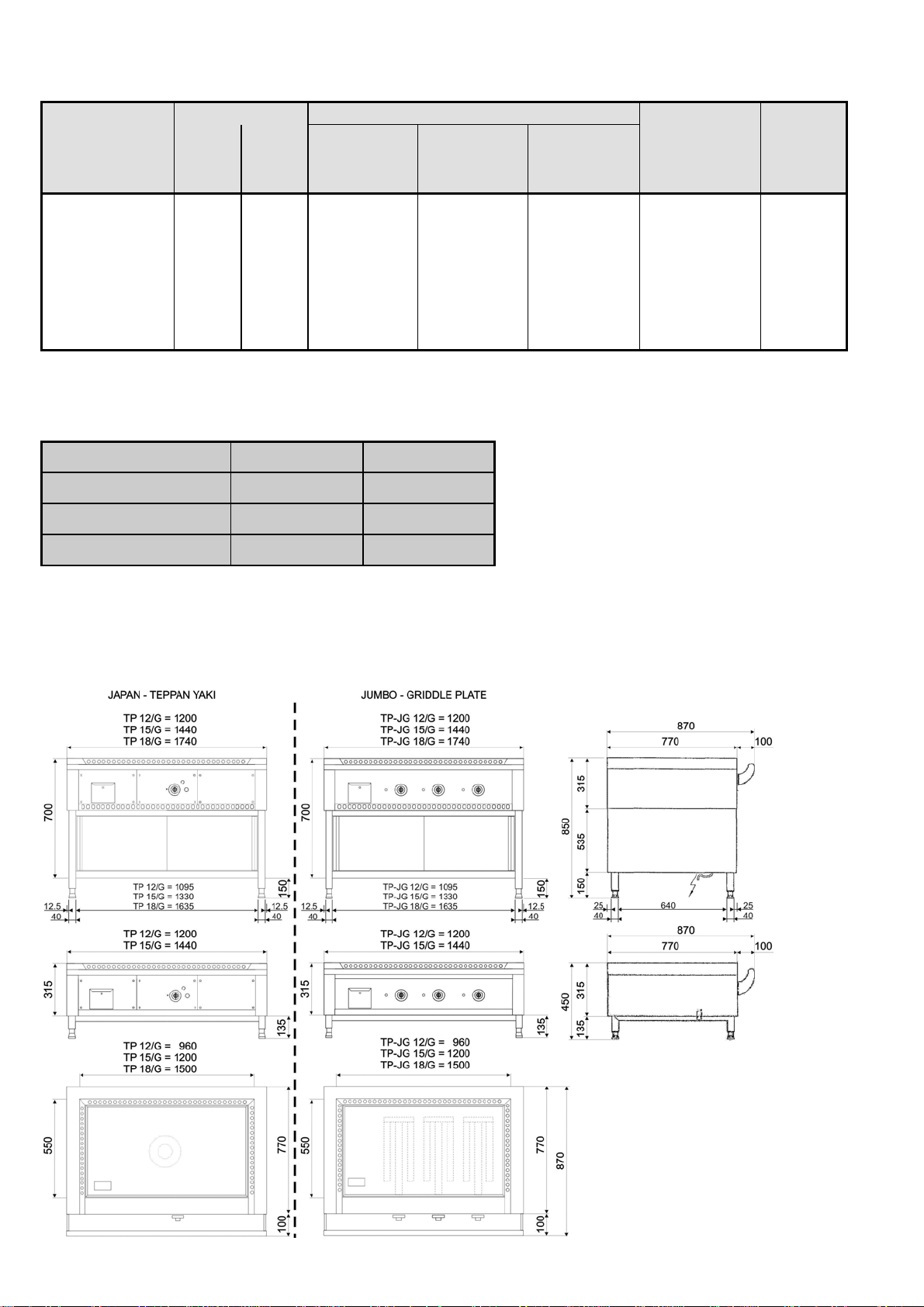
1.2 Place of Installation / Setting Appliance
The appliance must be placed on a stable solid platform. The platform must be flat and horizontal. When placed on
a table, this must be of non-combustable material.
If the appliance on the wallside is connected with flexible tubes, then the appliance must be screwed to the
platform.
This fixation is a must for the Table Models.
If the appliance is placed near temperature sensitive parts (f.i. furniture, electric cables in the wall) there has to be a
distance of 100 mm to the rear wall and 200 mm to the side walls.
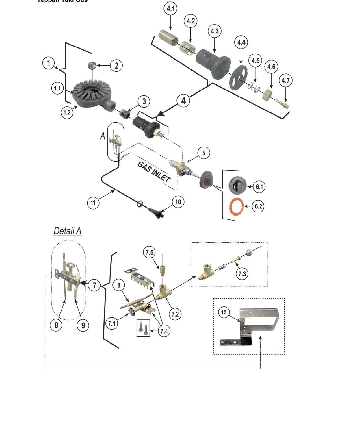
1.3 Gas connection
Before connecting the appliance, control if the gas type corresponds to the gas type od the place of installation.
If this is not the case an adjustmanet must be made before starting up the appliance.
If flexible tubes are used, these tubes must be in DIN 3384. (Depending of the countries, those which are
allowed)
In the gas inlet there must be a gas stop cock, fixed in a suitable position.
Depending on national requirements, a thermo stop cock must be installed before the appliance.
After connection, all gas pipes must be checked with foam or leck sprays under pressure for identifying gas leaks.

3
2. Technical Data (valid only for DE / CH / AT)
The appliance is suitable for operation of earth- or liquid gas
Category II 2 ELL 3 B/P (DE)
II 2 H 3 B/P (AT/CH)
call pressure
allowed connection
pressure Ranges
Earth gas 20,0 mbar 18,0 - 25,0 mbar
Liquid gas 50,0 mbar 42,5 - 57,5 mbar
Outside this range the appliance may not be operated.
2.1. Technical Data (valid for EU)
The appliance is suitable for operation of earth- or liquid gas / Construction A1
Category II 2 ELL 3 B/P
Countries
Category
connection pressure
(mbar)
2. family 3. family
Earthgas Liquid gas
AT II2H3B/P 20 50
BE II2E+3+ 20/25 28-30/37
CH II2H3B/P 20 50
DE II2ELL3B/P 20 50
DK II2H3B/P 20 28-30
ES II2H3+ 20 28-30/37
FI II2H3B/P 20 28-30
FR II2E+3+ 20/25 28-30/37
GB II2H3+ 20 28-30/37
GR II2H3+ 20 28-30/37
IE II2H3+ 20 28-30/37
IT II2H3+ 20 28-30/37
LU I2E 20
NL II2L3B/P 25 28-30
NO I3B/P 28-30
PT II2H3+ 20 28-30/37
SE II2H3B/P 20 28-30
2.2 Type of construction
The machines are classified in the following types of construction:
type Type of
construction
TP-JG 12/G A1
Machines of type B 21
have to be set up under
a dust marching off
machine.
TP-JG 15/G B21
TP-JG 18/G B21
TP 12/G A1
TP 15/G A1
TP 18/G B21

4
2.3 Heat load, gas connection values, combustion requirement, exhaust quantity
Type
Heat loader Gas connection value
Combustion
requirement Exhaust
quantity
Full fire
Minor
fire
Earth gas E
Earth gas H
(G20)
HuB 9,45 kWh/m3
Earth gas L
Earth gas LL
(G 25)
HuB 8,12 kWh/m3
Liquid gas
(G 30/G 31)
HuB 12,68 kWh/kg
TP-JG 12/G 10 kW 2,8 kW 1,06 m
3
/h 1,23 m
3
/h 0,79 kg/h 11,2 m
3
/h 12,2 m
3
/h
TP-JG 15/G 15 kW 5,6 kW 1,59 m
3
/h 1,85 m
3
/h 1,18 kg/h 16,8 m
3
/h 18,3 m
3
/h
TP-JG 18/G 15 kW 5,6 kW 1,59 m
3
/h 1,85 m
3
/h 1,18 kg/h 16,8 m
3
/h 18,3 m
3
/h
TP-12 / G 10 kW 4 kW 1,06 m
3
/h 1,23 m
3
/h 0,79 kg/h 11,2 m
3
/h 12,2 m
3
/h
TP-15 / G 10 kW 4 kW 1,06 m
3
/h 1,23 m
3
/h 0,79 kg/h 11,2 m
3
/h 12,2 m
3
/h
TP-18 / G 10 kW 4 kW 1,06 m
3
/h 1,23 m
3
/h 0,79 kg/h 11,2 m
3
/h 12,2 m
3
/h
The small combustion load is 2.8 kW for TP-JG… /G each burner and 4.0 kW for TP- /G each burner.
This results in the following FLOW VALUES each burner:
TP-JG.../G TP-…/G
Earth gas H, E (G20) 0,30 m3/h 0,48 m3/h
Earth gas L, LL (G25) 0,34 m3/h 0,55 m3/h
Liquid gas (G30)/(G31) 0,22 kg/h 0,35 kg/h
The machine is working with full fire with fixed nozzles without pre-adjustment.
For the pilot flame the small combustion quantity is regulated for liquid gas with fixed nozzles. For earthgas the
nozzles are adjusted.

5
3. Instruction of Users
The user must be instructed how to operate the appliance. The instruction for use must be kept to the user. The
user must be told that after construction changes in the room, which affects the combustion supply, the operation
control must be carried out.
4. Operation
4.1 Operation elements
4.2 Start up Burner (open cooking place)
Before operation the main gas cock on the appliance must be opened.
Then press the knob of the safety tap “A“ and turn same anti clockwise .
Keep the knob pressed in and ignite with ignition pistol the pilot flame..
After pilot flame burns, knob “A“ must remain pressed in for 15-20 seconds. If after releasing knob ”A” the
pilot flame continues burning, then the appliance is operable.
If the pilot flame goes out, you have to repeat the ignition process.
Now turn gas valve handle “B” anti clockwise to the required position between full combustion and small
combustion.
Knobs for the open cooking places
“out“
Pilot ignition position
MAX. position
MIN. position
4.3 Closing of burner
If the burner is only temporary to be cut, the gas cock with handle must be placed clockwise into position, so that
the appliance remains operable.
For longer periods of interruption, the gas cock with handle must be placed into position - -. The main gas
armature is to be closed.
5. Important Notice
The appliance is for commercial use and should be operated by qualified staff.
During operation the appliance must be attended.
It is necessary to have the appliance checked at regular intervals.
The time of checking depends on the use.
The checking must take place at least once a year.
The frying plate keeps hot long time after use. Attention of burning danger!
The fat collecting drawer(C) should be taken out the machine after complete cooling down, to
avoid burning caused of hot fat.
In case of problems, the appliance must be cut off. The main gas cock must be closed and the service engineer is
to be called.
An eventual change of the gas type may only be carried out by the producer or ist service agent.
A = Knob for burner
B = Piezo igniter
C = Fat collecting drawer
D = Opening for observation
of the pilot flame
C
A
B D

6
6. Cleaning
The cleaning should be carried out after each use of the appliance.
Before cleaning all armatures must be placed in position -O-. The main gas cock is to be closed.
Clean with warm water, if required some detergent, non aggressive cleaner.
A strongly dirty plate can be pre cleaned with a scraper.
For cleaning do not use steel wool or scraper, since corrosion could occur also on stainless steel.
The frying plate should be rubbed with a oil soaked cloth, to avoid corrosion.
➪Attention! Don’t clean the range with high pressure water
The range will be have more long use life and smooth work, if you have regular clean every day.
7. Service
The appliance requires a regular service. We recommend a service contract.
Service and repairs may only be carried out by the producer or service agent with qualified staff.
For Service and repairs only original parts should be used.
During Service, security arrangements of the appliance, function of burners and operation of burning operation is to
be checked. It is to control that no lift off or back stroke of the burners in hot condition occurs.
All gas pipes and parts must be controlled for closeness. Slits of the burners and nozzles in the primary air
segment must be free of foreign debris.
The gas armatures must be checked for easy of operation. In case of heavy movements, requires the exchange of
these parts. Application of grease, in exceptional cases may only be done by the service engineer. Sealed parts of
the producer may not be touched by the service engineer. If apart from the listed works other repairs should be
required, same should be done.
Only proper handling of the appliance, regular service by service technicians, guarantees problem free function of
the appliance with operation security.
This is also in view of legal regulations for technical equipment as well as accident regulations.
8. Behaviour in disturbances
Disturbances can occur due to mistakes in the gas supply, dirtiness of functioning parts, wrong handling or failing
ignition, regulators, function of control parts.
If the gas supply is ok., all functioning parts clean, wrong handling excluded, you have to call a service engineer.
In case of disturbances the gas armature (main gas cock) must be closed.
Repairs may only be carried out by qualified service engineers under consideration of ruling regulations for
operation and installation.

7
Spare parts list for JUMBO GRIDDLEPLATE Types: TP-JG …/G
Spare parts list types TP-JG ... / G
NO°. DESCRIPTION P/N QTY
TP-JG 12 / G TP-JG 15 / G
TP-JG 18 / G
1 Burner GS 3648 2 3
2 Injector Ø 1,0 (Propangas 50mbar)
Injector Ø 1,65 (Earthgas 20mbar) GS 3835
2 3
3 ABS knob GS 3602 2 3
4 Security tab GS 3875 2 3
4.1 Security tab GS 3875 2 3
4.2 By pass screw Ø 0.95 mm (small flame) GS 3687 2 3
4.3 Magnet for security Ø 10,5mm GS 8036 P 2 3
5 Piezzo igniter GS 3863 2 3
6 Spark plug cable 600 mm GS 3682 2 3
7 Spark plug GS 3856 2 3
8 Pilot burner DBL GS 3851 2 3
8.1 Pilot bracket GS 8042 P 2 3
8.2 Pilot head GS 8041 P 2 3
8.3 Pilot body GS 8040 2 3
8.4 Spring for pilot GS 8039 2 3
8.5 Nozzle for pilot GS 3828 2 3
8.6 Seal for pilot GS 8038 P 2 3
8.7 Taking off screw for pilot GS 8037 P 2 3
9 Thermocouple M9 x 1/600 mm GS 3895 2 3

8

9
Spare parts list TEPPAN YAKI GAS Types: TP …/G
NO° DESCRIPTION P/N
QTY
TP 12 / G
TP 15 / G
TP 18 / G
1 Burner set NS 9001 GS 8020 S 1
1.1 Burner head NS 9001 GS 4030 1
1.2 Burner base NS 9001 GS 4023 1
2 Plug 3/8“ x 1/4" for burner GS 4232 1
3 Pipe to burner base NS 9001 SP 8903 1
4 Primary air control assy complete with Venturi GS 8000 S 1
4.1 Inside pipe to air chamber GS 2826 1
4.2 Air chamber bush - inside GS 2825 1
4.3 Case of primary air mixing chamber GS 4357 1
4.4 Air mixing chamber plate - outside GS 4358 1
4.5 Spring for primary control assy GS 1456 1
4.6 Fixing bush for primary air control assy 1 ¼” GS 2851 1
4.7 Nozzle Ø 1,4 mm (Propangas 50mbar)
Nozzle Ø 2.5 mm (Earthgas 20mbar) GS 282 C
GS 282 J 1
5 Safety Gas Cock GS 3875 1
6.1 ABS Knob for gas valve GS 3602 1
6.2 Label Ring for gas knob GS 3862 1
7 Pilot burner DBL GS 3851 1
7.1 Pilot haed (3 flames) SP 385A 1
7.2 Pilot body with taking off screw & fixing spring for
nozzle SP 385B 1
7.3 Nozzle for pilot burner DBL - 0.20mm (LPN)
0.35mm (LNG) SP 385F
SP 385C 1
1
7.4 Pilot bracket (3 pieces-bracket) with fixing screw SP 385D 1
7.5 Pilot – fixing screw 6mm for gaspipe SP 385E 1
8 Thermocouple M9×1/1000mm GS 3890 1
9 Ignition plug GS 3856 1
10 Piezo Igniter GS 3720 1
11 Cable for ignition plug 600mm (2,8Ø0,6mm) GS 3682 1
12 Support and cover for pilot burner TP SP 9602 1

10
TROUBLE SHOOTING
N° TROUBLE CAUSE CHECK / REPAIR
1
The igniter does not function
- The cable of igniter is disconnected
- The igniter is damaged
- Check and repair
- Change (call a technician)
2
The pilot burner does not light
- Gas runs out
- The gas line to pilot burner is closed
- The hole of nozzle Tipp of pilot burner
is closed
- Check and fill gas
- Check and clean
3
The burner flame is yellow
- The primary air adjuster is closed
- The burner is dirty
- Check and open the primary air
adjuster
- Clean with brush
4 The burner does not light - The gas cock is damaged - Check and change
5
The pilot flame lights but it
extinguishes again
- The thermocouple is slacked
- The thermocouple does not produce
voltage (mv)
- The thermocouple is dirty
- Check and tight
- Check with Milivoltmeter, if the
thermocouple is damaged,
change it
- Check and clean

12
9. Gas conversion
The gas conversion may only be carried out by a qualified service engineer authorized by the producer.
Before conversion, you have to know the gas conditions ( type, gas pressure).
9.1 Technical DATA (valid only for DE / CH / AT)
The applience is for operation of earth- or liquid gas
Category: II 2 ELL 3 B/P (für DE)
II 2 H 3 B/P (für AT/CH)
Call pressure
Allowed connection
pressure ranges
Earth gas 20,0 mbar 18,0 - 25,0 mbar
Liquid gas 50,0 mbar 42,5 - 57,5 mbar
Beyond these pressure ranges the appliance may not be operated!
9.2 Technical data (valid for EU)
The appliance is for operation of earth- or liquid gas / Construction A1
Country of
destination
Category
Pressure ranges (mbar)
2. family 3. family
Earth gas Liquid gas
AT II2H3B/P 20 50
BE II2E+3+ 20/25 28-30/37
CH II2H3B/P 20 50
DE II2ELL3B/P 20 50
DK II2H3B/P 20 28-30
ES II2H3+ 20 28-30/37
FI II2H3B/P 20 28-30
FR II2E+3+ 20/25 28-30/37
GB II2H3+ 20 28-30/37
GR II2H3+ 20 28-30/37
IE II2H3+ 20 28-30/37
IT II2H3+ 20 28-30/37
LU I2E 20
NL II2L3B/P 25 28-30
NO I3B/P 28-30
PT II2H3+ 20 28-30/37
SE II2H3B/P 20 28-30

13
9.3. Heat load, Gas connection values
Obtain the heat load.
The appliance is operated in full combustion with fixed nozzles without prior adjustment.
For the main burner and pilot flame, small combustion for liquid gas is obtained with fixed nozzle, for earth gas the
nozzle has to be regulated.
Type
Heat load Gas connection values
Full fire
Minor
fire
Earth gas E
Earth gas H
(G20)
HuB 9,45 kWh/m3
Earth gas L
Earth gas LL
(G 25)
HuB 8,12 kWh/m3
Liquid gas
(G 30/G 31)
HuB 12,68 kWh/kg
TP-JG-12/G 10 kW 2,8 kW 1,06 m
3
/h 1,23 m
3
/h 0,79 kg/h
TP-JG-15/G 15 kW 5,6 kW 1,59 m
3
/h 1,85 m
3
/h 1,18 kg/h
TP-JG-18/G 15 kW 5,6 kW 1,59 m
3
/h 1,85 m
3
/h 1,18 kg/h
TP-12 / G 10 kW 4 kW 1,06 m
3
/h 1,23 m
3
/h 0,79 kg/h
TP-15 / G 10 kW 4 kW 1,06 m
3
/h 1,23 m
3
/h 0,79 kg/h
TP-18 / G 10 kW 4 kW 1,06 m
3
/h 1,23 m
3
/h 0,79 kg/h
The small combustion load is 2.8 kW for TP-JG… /G each burner and 4.0 kW for TP- /G each burner.
This results in the following FLOW VALUES each burner:
TP-JG.../G TP-…/G
Earth gas H, E (G20) 0,30 m3/h 0,42 m3/h
Earth gas L, LL (G25) 0,34 m3/h 0,49 m3/h
Liquid gas (G30)(G31) 0,22 kg/h 0,32 kg/h
The appliance is operated in full combustion with fixed nozzles without prior adjustment.
For the main burner and pilot flame, small combustion for liquid gas is obtained with fixed nozzle, for earth gas the
nozzle has to be regulated
9.4 Nozzle list
Type of gas Pressure
(mbar)
type TP-JG.../G type TP-…/G burner
Full combustion
Minor
combustion Full combustion
Minor
combustion
Earth gas H,E G20
20 Ø 1,65 mm regulated Ø 2,30 mm regulated regulated
Earth gas H,E G20
20/25 Ø 1,65 mm regulated Ø 2,30 mm regulated regulated
Earth gas LL G25
20 Ø 1,80 mm regulated t Ø 2,40 mm regulated regulated
Earth gas L G25
25 Ø 1,65 mm regulated t Ø 2,30 mm regulated regulated
Liquid gas G30/31
50 Ø 1,00 mm Ø 0,90 mm Ø 1,25 mm Ø 0,90 mm Ø 0,20 mm
Liquid gas G30/31
28-30 Ø 1,13 mm Ø 0,95 mm Ø 1,50 mm Ø 1,00 mm Ø 0,20 mm
Liquid gas G30/31
28-30/37 Ø 1,13 mm Ø 0,95 mm Ø 1,50 mm Ø 1,00 mm Ø 0,20 mm
9.5. Nozzle change
Types TP... / G: In case of change of the pilot flame nozzle as well as adjustment of the burner flame; the frying
plate should be taken off the machine.
For that the frying plate should be completely cooled down.
Attention: The frying plate is heavy!

14
9.5.1. Nozzle change type TP ... /G
Lift frying plate. Remove fixing screw (1). Lift burner (2) abt. 10 mm
and pull away from the mixing chamber (3).
Remove then the complete mixing chamber (3) by turning same anti-
clockwise from the nozzle. Turn the pressure ring (4) from the nozzle.
Pay attention that the built in pressure ring is not lost.
Remove the nozzle from the nozzle carrier and replace a new nozzle
according the nozzle table for use in the country of operation and gas
type required.
The nozzle must be fixed with a non-hardening sealing tape.
Then replace the burner by following instructions in the opposite
direction. Pay attention also to “primary air adjustment“.
We recommend to check the pilot flame and nozzles before rebuilding.
9.5.2 Nozzle change type TP-JG ... / G
Take out the fat collecting drawer and take off the ABS
knob.
Remove the nozzle from the nozzle carrier and replace a
new nozzle according the nozzle table for use in the
country of operation and gas type required.
The nozzle must be fixed with a non-hardening sealing
tape.
10. Small combustion adjustment
For the Combi Wok burner (soup burner) the small combustion adjustment must be regulated to 4,5 kW for
earthgas.
The nozzle bore in the small combustion nozzle is 50 mbar and 30 mbar.
To regulate for earthgas proceed as follows:
Operate burner in small combustion.
Turn off handle of the security control knob.
With a small screw driver adjust small combustion nozzle (9) that 4 kW are obtained.
(Turn Clockwise reduces warmth load, turn anti clockwise increases warmth load).
The adjustment of the warmth load can be done according volume method, see flow chart.
The adjustment of the warmth load must be such that the burner in hot or cold,
ignites properly.
For changing to liquid gas the small combustion nozzle (9) turn slightly against the stroke.

15
11. Pilot flame adjustment
The Pilot flame must be regulated for earthgas. This is done as follows:
Pilot flame ignite covering screw (10) with washer (11). Remove with small
screw driver, nozzle (C) adjust that main burner ignites well. Turn
Uclockwise reduce gas flow, anti clockwise increases gas quantity.
When operated with liquid gas, nozzle (C) turn clockwise towards stroke.
After regulating washer (11) and covering screw (10) fix gas tight.
12. Primary air adjustment
The primary air is fixed and sealed by the producer according to the country
of use and the gas type required. The adjustment is mentioned on the
packing and the type shield.
If a gas change must be undertaken, the primary gas adjustment must
follow the table below:
Type Earth gas E(H)
20mbar Earth gas L (LL)
20 mbar Earth gas L
25 mbar Liquid gas
28-30/37 mbar
Liquid gas
50 mbar
TP-JG.../G (H) = 14 mm 14 mm 14 mm 16 mm 14 mm
TP.../G Nut (B) = 15 mm 15 mm 15 mm 15 mm 15 mm
Injector (A) = closed closed closed closed closed
Primary air adjustment types TP-JG ... / G Primary air adjustment types TP ... / G
13. Tests
After a conversion the following requirements must be fulfilled:
Nozzle diameter and pressure must be identical to the indication of the producer
The tightness of all gas pipes and parts must be secure
Ignition, through ignition, over ignition must be guaranteed for full combustion and small
combustion operation
The flame may not lift off nor beat back to the nozzles
All burners, ignition and control arrangements must be checked for dirt, secureness and function
The closing time of the thermo electric ignition control may not exceed 60 seconds
14. Sticker
After a conversion of a gas type has been carried out a new sticker must be placed on the appliance which shows
clearly the new gas type and gas pressure.

16
TROUBLE SHOOTING
N° TROUBLE CAUSE CHECK / REPAIR
1
The igniter does not function
- The cable of igniter is disconnected
- The igniter is damaged
- Check and repair
- change (call a technician)
2
The pilot burner does not light
- Gas runs out
- The gas line to pilot burner is closed
- The hole of nozzle Tipp of pilot burner
is closed
- Check and fill gas
- Check and clean
3
The burner flame is yellow
- The primary air adjuster is closed
- The burner is dirty
- Check and open the primary air
adjuster
- Clean with brush
4 The burner does not light - The gas cock is damaged - Check and change
5
The pilot flame lights but it
extinguishes again
- The thermocouple is slacked
- The thermocouple does not produce
voltage (mv)
- The thermocouple is dirty
- Check and tight
- Check with Milivoltmeter, if the
thermocouple is damaged,
change it
- Check and clean
This manual suits for next models
7
Table of contents
Other Diamond Burner manuals
Popular Burner manuals by other brands

ECOSTAR
ECOSTAR ECO 50 Installation, operating and maintenance manual

BLUE STONE
BLUE STONE ICB-6821 user manual

ECOSTAR
ECOSTAR GRM 40 Installation, operating and maintenance manual

Real Fyre
Real Fyre G45-16/19A-SS owner's manual

Elster
Elster Eclipse AirHeat AH operating instructions

Ecoflam
Ecoflam MAX GAS 170 PR manual

Primus
Primus LITE+ 3560 manual

Ecoflam
Ecoflam MAX GAS 350 P manual

Riello
Riello RDB1 50 Installation, use and maintenance instructions

Riello
Riello RDB 2.2R BG 24 kW Installation, use and maintenance instructions

baltur
baltur TBG 2000 MC INSTALLATION, USE AND MAINTENANCE INSTRUCTION MANUAL

Ecoflam
Ecoflam MAX 1 manual