Diamond CSL1007-VTB User manual

Mod: CSL1007-VTB
Production code: HPL/1004-P
07/2018

MANUAL
HPL

Bertrand Manufacturer - 3
General rules ..................................................................................................................................... 04
Technical data .................................................................................................................................. 05
Hoods HPL 1004 - 1504 - 2004 - 2504 .......................................................................................... 05
Characteristics .................................................................................................................................... 05
Fans DDM 7/7 - DDM 8/9 ................................................................................................................. 06
General information ........................................................................................................................... 06
Description and technical features ................................................................................................... 06
Description ......................................................................................................................................... 06
Technical features and intended use .............................................................................................. 06
Security measure .............................................................................................................................. 06
Installation manual ............................................................................................................................ 07
Use and operation ............................................................................................................................ 07
CE- declaration of incorporation mod. DDM 7/7 ............................................................................ 08
CE- declaration of incorporation mod. DDM 8/9 ............................................................................ 09
Data plate .......................................................................................................................................... 10
Wiring diagram .................................................................................................................................. 10
Digital speed control ...................................................................................................................... 11
General information ........................................................................................................................... 11
Basic operation characteristics ......................................................................................................... 12
Main features ..................................................................................................................................... 12
Procedure for controlling the engine speed .................................................................................... 12
Installation of the controller ............................................................................................................... 13
Placement of lters and divider .................................................................................................... 14
....
Installation of the lters ..................................................................................................................... 14
1.
1.1
1.2
2.
2.1
2.2
2.2.1
2.2.2
2.3
2.4
2.5
2.6
2.7
2.8
2.9
3
3.1
3.2
3.3
3.4
3.5
4
4.1
CHAPTER PAGEDESCRIPTION
INDEX

4- Bertrand Manufacturer
GENERAL RULES
• Attentively read the following instructions , because they contain important information of security, use and mainte-
nance of the appliance.
• Save these “instructions for use”, so several users of the appliance can consult them at any time.
• Make sure the appliance is complete after the unpacking.
• In case of doubt, don’t use the appliance and consult qualied personnel
• The appliance can only be used by qualied personnel.
• Before cleaning or maintenance of the appliance, or in case of breakdown or bad functioning, always close the gas and
water supply.
• In case of repair , always ask technical qualied assistance and ask to use original spare parts.
• The non-respect of this instructions can endanger the security of the appliance.
• The appliance has to be in accordance with the norms and realised according to the instructions of the constructor.
• Do not clean the appliance with high-pressure cleaning machines.
• Do not close openings for gas and air supply, or emitting of heat.
• To avoid risks of rust or chemical aggression, good cleaning of the surfaces in stainless steel is advised.
• To bring the appliance in state of security, when not used
IF THE INSTRUCTIONS IN THIS MANUAL ARE NOT RESPECTED, NEITHER BY THE USER, NEITHER BY THE
INSTALLER, THE COMPANY WILL ABANDON EVERY RESPONSIBILITY AND ANY ACCIDENT OR DEFECT
CAUSED BY IGNORANCE OF THE FOLLOWING CANNOT BE ATTRIBUTED TO THE CONSTRUCTOR.
THE CONSTRUCTOR WILL ABANDON EVERY RESPONSIBILITY ACCORDING TO POSSIBLE INCORREC-
TNESS IN THIS MANUAL, DUE TO TRANSCRIPTION OR PRINTING.
THE MORE, HE MAINTAINS THE RIGHT TO MAKE NECESSARY AND USUAL MODIFICATIONS TO THE PRO-
DUCT AND THIS WITHOUT DENIAL OF THE ESSENTIAL CHARACTERISTICS.

1 - Manual - Technical Data
Bertrand Manufacturer - 5
1. TECHNICAL DATA
P
C
A
C
L
197
B
H = 460
HPL/1004 HPL/1504 HPL/2004 HPL/2504
Dimensions in mm ( P X L x H ) 1000 X 900 X 460 1500 X 900 X 460 2000 X 900 X 460 2500 X 900 X 460
Air suction holes - n° - dimensions in mm A X B n°1 - 232 X 132 n°1 - 232 X 132 n°1 - 298 X 132 n°1 - 298 X 132
Labyrinth lters 400 X 500 2 2 2 2
Labyrinth lters 500 X 500 1 2 3
Dividers 2 2 2 2
Indicator lamp - n° - W n°1 - 18W n°1 - 36W n°1 - 58W n°1 - 58W
Vacuum DDM 7/7 (230/1/50 - 1,6A - 147W - 1400 Rpm) 1 1
Vacuum DDM 8/9 (230/1/50 - 3,15A - 420W - 1400 Rpm) 1 1
Airow in m³/h 1500 1500 2500 2500
Digital speed indicator with solenoid valve and light switch 4,5A - 230V 4,5A - 230V 4,5A - 230V 4,5A - 230V
Injection holes A1 x B1 NO NO NO NO
Recessed lighting (with plexi cover) YES YES YES YES
Welded gutter to collect grease NO NO NO NO
Fully welded NO NO NO NO
Volume without packaging 1,03 1,03 1,36 1,69
Weight without packaging 40 45 55 65
• Monobloc hood made of stainless steel with brushed and polished nish.
• Hood assembled by electronic point welding.
• Labyrinth lters in stainless steel network.
• Special anti-drip chute for grease collection.
• Tap drainage for grease.
Where provided :
• IP65 lamp with or without built-in lighting.
• Built-in vacuum 230/1/50 IP55, ERP 2015.
• Speed regulator 4,5A IPSS.
• Welded gutter to collect grease on hoods with recessed lighting.
1.1 Hoods HPL 1004 - 1504 - 2004 - 2504
1.2 Caractéristiques

2 - Manual - Fans
6- Bertrand Manufacturer
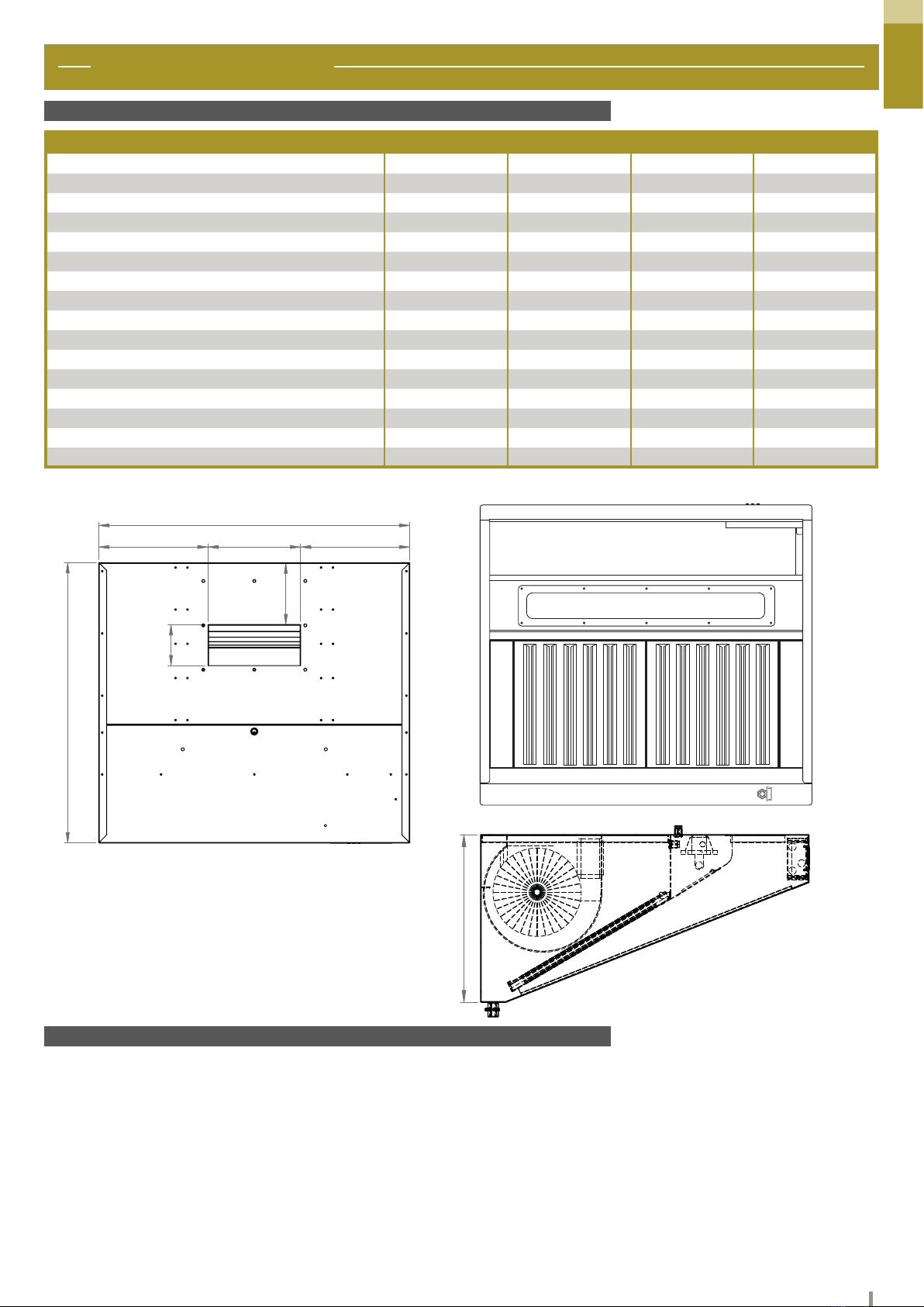
2. FANS DDM 7/7 - DDM 8/9
2.1 General information
2.2 Description and technical characteristics
2.3 Security measure
This manual is directed to manufacturers, installers and service agents of ventilation equipment specialized in the appli-
cation, installation and adjustment of industrial fans.
2.1.1 Purpose and limits of the use of the manual :
This manual is intended for specialized and adequately trained personnel in the realization of machines or equip-
ment using centrifugal electric fans, preventing preventive errors from the use and installation of such devices.
However, the present recommendations are not the only methods, procedures or other devices for obtaining
security in the represented situations. Always be rigorously careful when moving around moving parts or parts
under tension. Safety depends only on skill, experience and reasonable attention in the actions performed on the
machine.
To operate safely on the electronic fan during installation and maintenance, use individual protective equipment (eg.
gloves) as provided for in Directive 89/686 / EEC (and its successive amendments).
2.2.1 Description :
For a description of the fans, refer to the manual.
2.2.2 Technical features and expected use :
The current electric fan is adapted to transfer non-toxic, non-ammable, non-corrosive air without liquid or solid or
abrasive particles and the temperature does not exceed 40 ° C (UNI EN ISO 13349).
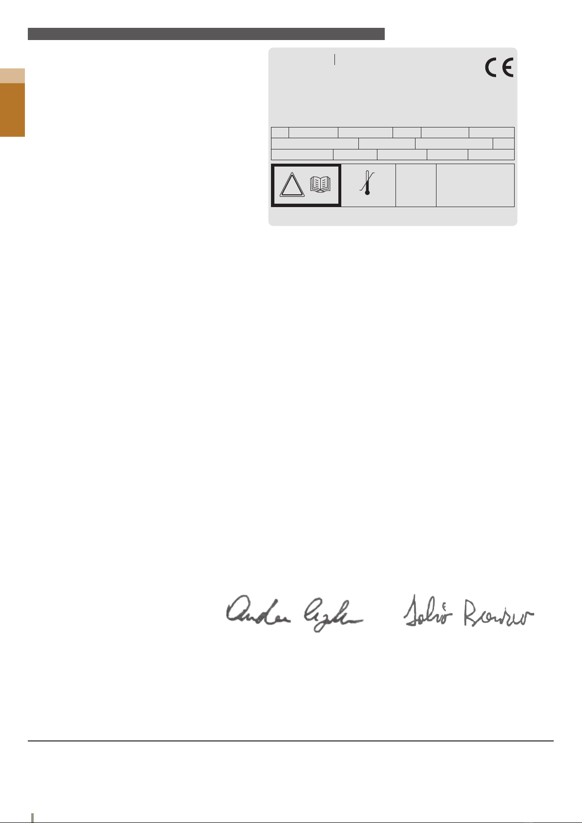
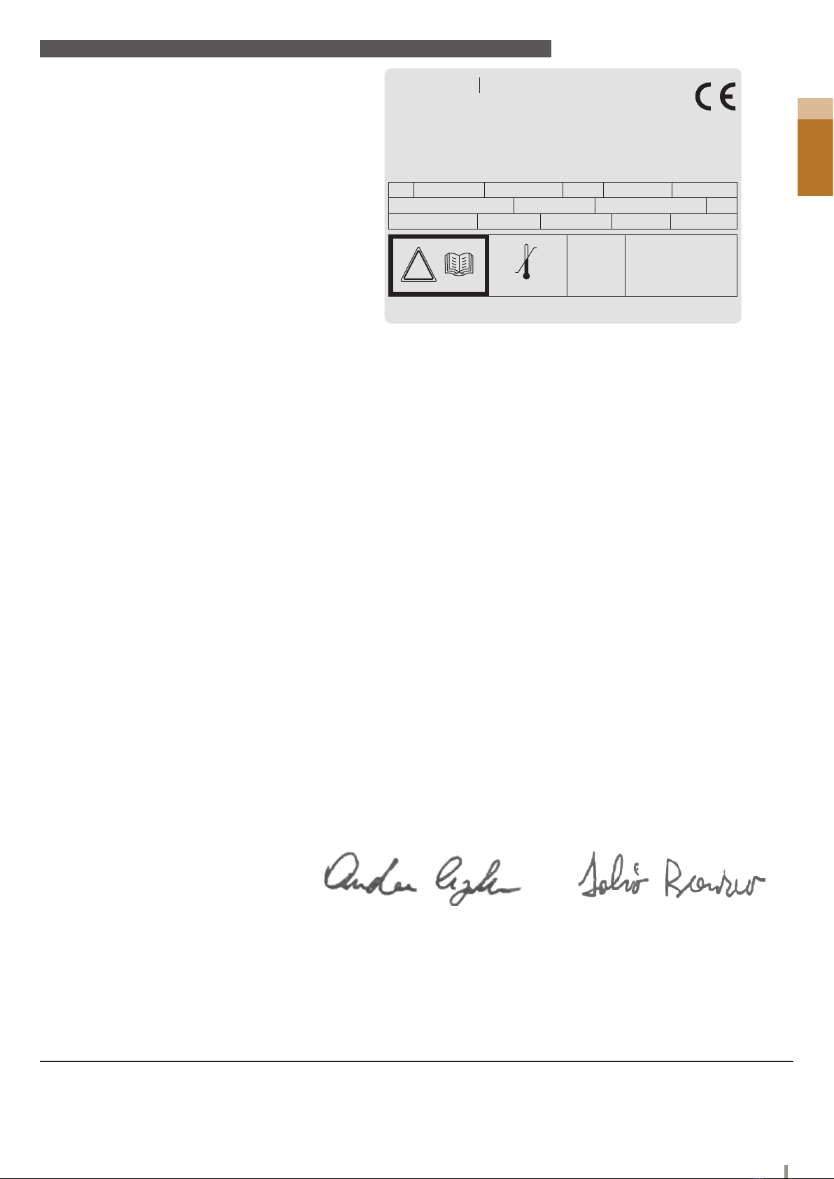
Different temperature and humidity limits are indicated on the fan label. The electric fan must only be operated
with the electrical power supplied by the indication on the label.
In addition to these recommendations, before performing any activities related to the use of this machine, you
must be informed of the required security applications based on the laws, rules and standards applicable to the
installation site
Displacement, installation and maintenance must always be carried out by
trained and trained technicians.
Any installation by unskilled people is therefore prohibited
Attention: The current electrical fan is built to be mounted in a machine and therefore cannot be used
autonomously.
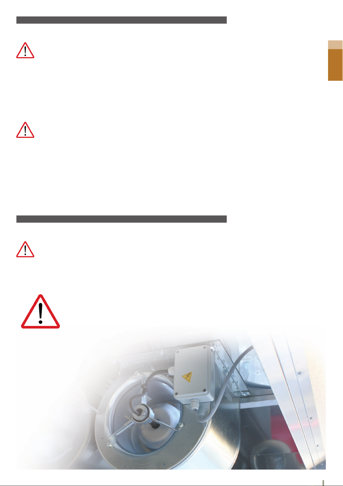
Attention: the present electric fan must be protected against the risks of mechanical type, the risks due
to the projection, the risks due to the electric energy and the risks due to the extreme temperatures (the
engine can reach surface temperatures above 70 °C) in all cases the electric fan must be installed on the
machine taking into account all necessary safety measures, in order to avoid any danger arising from its
application, in accordance with the requirements of Machine Directive 2006/42 / EC (and its successive
amendments). As an indication, we advise you to apply the content of technical standards UNI EN ISO
12100, UNI EN ISO 13857, CEI EN 60204, UNI EN ISO 12499.
Note: the sound power level emitted by the machine is indicated on the label when it exceeds Leq = 85db
(A). The weight of the fan is indicated on the label when it exceeds 30kg. These indications must be taken
into account to provide the appropriate protection for the machine.

2 - Manual - Fans
Bertrand Manufacturer - 7
2.4 Installation operations
2.5 Use and operation
The correct installation of the electric fan ensures the solution of many problems that could arise during its use.
The fan must be used only for the purpose for which it was designed (par.2.2.2) and introduced into the machine with all
the protections to prevent any risk to persons and things.
Use out of predetermined limits can lead to dangerous situations not considered and independent of the responsibility of
the manufacturer.
Installation phases:
a) check if parts are damaged or missing;
b) check that the wheel rotates freely and that there is no sign of excessive imbalance or play on the motor shaft
c) Insert the fan into the machine by securing it with the anchor holes on the fan housing or through the holes on the
ange, if tted, or holes of the brackets that are part of the supply. The electro ventilator must have a space between
the suction gates and the walls of the machine to not punish the aeroulic and sound characteristics, this distance must
at least be the diameter of the wheel. The diameter of the wheel can be found in the description on the label, which is
expressed in pulses (if it is three digits, it is expressed in millimetres);
d) connect the electric fan according to the attached connection diagram and also present on the electric fan, also
veries that the supply voltage for the test does not exceed the ones indicated on the label of the electric fan;
e) during the test phases of the machine, check that the direction of rotation coincides with that indicated by the
orientation arrow on the electric fan and that the current absorption does not exceed the one indicated on the label;
f) Check the protections specied by the project so that the machine complies with the requirements of the
89/392 / EEC directive in the protection of the electric fan, and that these are adequately installed.
CAUTION: do not remove the safety protections provided; do not intervene on
the electric fan without rst turning off the voltage and wait until the wheel has
stopped
Attention: the displacement of the electric fan could be difcult given its shape and the uneven distribu-
tion of the weights.
Attention: Turn off the power of the machine before you start the installation process.
Attention: the electric fan must be installed with the motor shaft placed horizontally with respect to the
ground
Caution: before operating the electric fan control that the voltage of the power supply corresponds to that
shown on the label
Attention: the electric fan must operate only within the limits of operation (power supply, temperature,
etc.) indicated on the label.

2 - Manual - Fans
8- Bertrand Manufacturer
2.6 EC-declaration of incorporation mod. DDM 7/7
069-2016
INSTRUCTION 985707
NICOTRA Gebhardt
MADE IN ITALY
Nicotra Gebhardt S.p.a. Via Montenapoleone, 9 20121 Milano
Stabilimento: Via Modena, 18 24040 Ciserano Loc. Zingonia (BG) - IT
mod. DDM 7/7 E5G3301 1F 4P +FL+SCT
code FN022T / 00 BATCH 831595
1.6/1.55 A.max 147 W 1200 RPM Th Y
1~ 50/60 Hz
ETA 38,8 % Total INST. B N 49 ErP 2015
230 V IP 55 C5 µFCl.Is.Mot. F
!
-20
+40
°C
The manufacturer :
Nicotra Gebhardt S.p.A.
Via Modena 18,
24040 Ciserano, Italy
Herewith declares, that the direct-driven fan, manufactured in the Nicotra Gebhardt plant in Ciserano (Zingonia), Italy,
and individually identied, according to its name-plate, by Product designation, Part number / Revision Batch n°,
qualies as a partly-completed machine, according to Article 2 clause (g), and does comply to the following basic requi-
rement of the Machine Directive (2006/42/EC): Annex I, Article 1.1.2, 1.3.7, 1.5.1.
The relevant technical documentation is compiled by Nicotra Gebhardt S.p.A., and stored at the same address above,
and the manufacturer accepts to transmit such documentation, on the partly completed machinery, on paper or in elec-
tronic format, in response to a reasoned request by the national authorities.
This partly-completed machine must not be put into service until the nal machinery into which it is to be incorporated
has been declared in conformity with the provisions of the Machine Directive (2006/42/EC).
Nictora Gebhardt S.p.A.- Italy -
Ufci amministrativi e commerciali:
Stabilimenti:
24040 Ciserano Loc. Zingonia (BG) - Via Modena, 18 - Tel. 035-873111 - Fax 035-884319
Place / Date
Ciserano, 21.04.2015
1) For a complete listing of applied standards and technical specications see manufacturer’s documentation
2) as far as harmonized standards are not existing
Andrea Cigada
Senior Vice President Operations
EMEA
Fabio Breviario
Chief engineer and Design Authority
R&D Manager
The following harmonized standards have been applied (1):
Safety of machinery - General principles for design - Risk assessment and risk reduction
Safety of machinery - Safety distance to prevent hazard zones being reached by upper and
lower limbs (this particular sandard applies to any inlet or outlet guard which may be included in
the design of each particular fan)
Safety of machines - Electrical equipement of machines
Part 1: General requirements
Applied National Technical Standards and Specications (2):
Fans - Safety requirements
EN ISO 12100
EN ISO 13857
EN 60204-1
VDMA 24167

2 - Manual - Fans
Bertrand Manufacturer - 9
2.7 EC-declaration of incorporation mod. DDM 8/9
069-2016
INSTRUCTION 985707
NICOTRA Gebhardt
MADE IN ITALY
Nicotra Gebhardt S.p.a. Via Montenapoleone, 9 20121 Milano
Stabilimento: Via Modena, 18 24040 Ciserano Loc. Zingonia (BG) - IT
mod. DDM 8/9 TIGHT E6G3405 +FL+SCT
code FN02250 / 00 BATCH 832191
3.15 A.max 420 W 1320 RPM Th Y
1~ 50 Hz
ETA 40,9 % Total INST. B N 49,1 ErP 2015
230 V IP 55 C12.5 µFCl.Is.Mot. F
!
-20
+40
°C
The manufacturer :
Nicotra Gebhardt S.p.A.
Via Modena 18,
24040 Ciserano, Italy
Herewith declares, that the direct-driven fan, manufactured in the Nicotra Gebhardt plant in Ciserano (Zingonia), Italy,
and individually identied, according to its name-plate, by Product designation, Part number / Revision Batch n°,
qualies as a partly-completed machine, according to Article 2 clause (g), and does comply to the following basic requi-
rement of the Machine Directive (2006/42/EC): Annex I, Article 1.1.2, 1.3.7, 1.5.1.
The relevant technical documentation is compiled by Nicotra Gebhardt S.p.A., and stored at the same address above,
and the manufacturer accepts to transmit such documentation, on the partly completed machinery, on paper or in elec-
tronic format, in response to a reasoned request by the national authorities.
This partly-completed machine must not be put into service until the nal machinery into which it is to be incorporated
has been declared in conformity with the provisions of the Machine Directive (2006/42/EC).
Nictora Gebhardt S.p.A.- Italy -
Ufci amministrativi e commerciali:
Stabilimenti:
24040 Ciserano Loc. Zingonia (BG) - Via Modena, 18 - Tel. 035-873111 - Fax 035-884319
Place / Date
Ciserano, 21.04.2015
1) For a complete listing of applied standards and technical specications see manufacturer’s documentation
2) as far as harmonized standards are not existing
Andrea Cigada
Senior Vice President Operations
EMEA
Fabio Breviario
Chief engineer and Design Authority
R&D Manager
Les normes harmonisées suivantes on été appliquées (1):
Safety of machinery - General principles for design - Risk assessment and risk reduction
Safety of machinery - Safety distance to prevent hazard zones being reached by upper and
lower limbs (this particular sandard applies to any inlet or outlet guard which may be included in
the design of each particular fan)
Safety of machines - Electrical equipement of machines
Part 1: General requirements
Applied National Technical Standards and Specications (2):
Fans - Safety requirements
EN ISO 12100
EN ISO 13857
EN 60204-1
VDMA 24167

2 - Manual - Fans
10
2.8 Information data plate
2.9 Connection diagram
INSTR. COD.
NICOTRA Gebhardt
Nicotra Gebhardt S.p.a. Via Montenapoleone, 9 20121 Milano - Italy
Stabilimento: Via Modena, 18 24040 Ciserano Loc. Zingonia (BG) - IT
mod.
COD. BATCH
11 A.max 12 W 13 RPM Th 14
5 6 Hz.
ETA 19 % 20 21 N 22 23
7 V. IP 8 10 µFCl. Is. 9
!
°C
15
18
M>
kg
16 Kg SWL dB (A)
17
>
1
2 3 4
1. description model
2. Nicotra code
3. Level of modication
4. Production lot number
5. Number of phases and current voltage
6. power supply frequency
7. power supply voltage
8. Protection index engine housing
9. Class of motor insolation
10. Convector value (if any)
11. Maximum current absorption
12. Rated engine power
13. Nominal number of revolutions
14. Presence of thermal protector (Y = yes / N =
no)
15. Reach operating temperature
16. Machines exceeding 30kg (if any)
17. Machines that exceed the sound power level of
85 dB (A) (if present)
18. User’s Guide instruction code
19. Total revenue
20. Revenue category (static or total)
21. category of measure used to determine energy
efciency
22. level of performance at the optimum point of
energy efciency
23. Erp comformity
MAIN
AUX
ORANGE
ORANGETH
YELLOW/GREEN
WHITE
BROWN
BLACK
POWER SUPPLY
BLACK
BLUE
RED
YELLOW
BROWN
GREEN
WHITE
YELLOW/GREEN
ORANGE
GREY
VIOLET
SPEED 1,2,3,4
PHASE
NEUTRAL

3 - Manual - Digital speed control
11
3. DIGITAL SPEED CONTROL
FE230 regulator is an advanced control system using a micropro- cessor for manual or
automatic speed adjustment of an induction single-phase motor (typically used for air
intake systems), for lighting system management and for a possible optional load
(such as, for example an external gas solenoid valve for chim- ney or gas outlet).
The precision and its use ease are guaranteed by using a latest generation
microprocessor and by digital controls situated on the front panel: picture 2 and the
following instructions illustrate the functions managed by FE230 control unit, these
functions turn the control unit into an ideal solution for many indoor and pro- fessional air
intake systems (odours, smokes and fumes extrac tors fan, indoor, professional and
industrial range hoods, purication and air treatment devices, etc...).
Special attention in designing FE230 control system has been dedicated to achieve an innovative electronic control sys-
tem, characterized in stand-by condition by lower power consumption cur- rently available for these kind of product.
This feature, particularly appreciated today, and the possibility to automate air intake system by optional sensors, allow
to install a sophisticated and efcient air-treatment system control in every kind of settings. The possibility of using
wireless remote control (IR/RADIO code FE1004) or RS- 485 serial channel turn FE230 system into a “clever” system
control that is able to set up new features that can be implemented according to custom requirements.
The manufacturer declares that this product is free from manufacturing defects. The guarantee lasts 12 months if the
product is correctly used.
The manufacturer reserves the right to make changes, also without notice, on the de- vice or on the documentation in
order to improve its performances.
WARNINGS:
•Before installing and plugging the device into the mains, check that the specications indicated on the data plate
and the technical characteristics explained on this manual correspond to those of the electrical mains system, of
motor, of lighting system and of eventual gas solenoid valve.
• Use always high quality and suitable section electric cables wire to connect the regula- tor to the mains and to
loads.
• We recommend that you keep within the device the lenghts cable short to avoid their contact with particular compo-
nents that could reach high temperatures.
• Install the regulator in ventilated places and away from sources of heat, especially if the current load absorption are
close to the maximum declared.
• Be sure to connect the ground wire of the motors (or the chassis of the motors) to the main board and the latter one
to the grounding system of the network.
•To avoid danger of re, electric shock or malfunctions, do not expose the device to rain, humidity, favouring the
installation in a dry place. It is recommended to not in- stall the regulator in areas with moisture, fumes or gas, avoid
direct sunlight or heat sources that could damage the device dissipation capacity.
• The regulator must be installed and used only in compliance with the instructions pro- vided: the manufacturer won’t
be responsible for the improper use of the device (if it is used for applications different than those for which it was
designed) or for failure to
Fig.1
3.1 General information

3 - Manual - Digital speed control
Key SW1 :
Pressing SW1 key, motor starts running and speed 1 is automatically setted: at
every start, it is however foreseen that the motor runs, for 3 seconds, at a different
speed (start speed). After 20 seconds, gas solenoid valve is turned on and led DL
lights on.
Key SW2:
Pressing SW2 key, gas solenoid valve is immediately disabled and led DL switches off:
Maximum speed motor is setted (speed 8) for 20 seconds, then it stops.
Key SW3:
Each press of SW3 key increases speed motor according to the scheme:
V1 —> V2 —> ... —> V7 —>V8.
Key SW4:
Each press of SW4 decreases speed motor according to the scheme: V8 —> V7 —> ... —> V2 —>V1.
Key SW5:
With motor off or motor running, pressing SW5 turns on or off light.
3.2 Technical characteristics
3.4 Procedure for controlling the engine speed
Single-phase power supply: 85-265 Vac 50Hz.
Fuse of general protection: 10AT 5 X 20 mm.
Stand-by power consumption (loads off) 0.35 W.
Phase control with triac: speed motor setting and switch with relay.
Motor: single-phase induction.
Maximum load MOTOR: 4,5A (@ 230 Vac).
Maximum load LIGHTS: 2A (@ 230 Vac).
Features for gas solenoid valve : 230 Vac 50Hz MAX. 1A
Possibility of receiving wireless remote controls by Radio remote control (optional).
Possibility of connecting optional sensors (temperature sensors, air-quality sensors, odour and gas sensors, relative
humidity sensor, CO2 sensors, anemometers, etc..)
Bidirectional serial communication channel RS-485 (optional).
Digital controls setting through 5 frontal keys, 1 led and 1 seven-segments display.
IP protection : IP55.
Size: 158x118x77 mm.
Weight: 0.37 kg.
References standards: EN 55014-1, EN 55014-2, EN 60204-1, EN 60335-1, EN 61000-3-2, EN 61000-3-3,
EN 61000-4-2, EN 61000-4-4, EN 61000-4-5.
3.3 Main features
In relation to the features described below, refer to g.2.
At motor switch on, a seven-segments display indicates numerical values between 1 and 8 representing speed motor
setting. In the transition from one speed to another one, as well as switching on and switching off, the motor always
follow a proper ramp.
SW3DIGIT
DL
SW1
SW4SW5 SW2
Fig.2
When loads are off, it is possible to do the calibration procedure of the motor speed, by which the user can customize
the value of the minimum, maximum and start speed. After completing the calibration procedure, intermediate speeds
(the speed 2 to 7) are dened by software based on the minimum and maximum setting.
If the user does not perform the calibration procedure for setting the minimum and maxi- mum motor speed, these pa-
rameters have default values.
Press and hold simultaneously for 3 seconds the keys SW3 and SW4 to access the cali- bration procedure of the motor
speed:
the display shows «0», indicating that it is enabled the start speed, and is automatically selected minimum speed that
can be associated to that parameter (it should be noted that this speed, depending on the type of load applied, it may
not be sufcient to start the motor:
in this case press the button SW3 to incre- ment until the motor starts).
Push the SW3 and / or SW4 to increase and / or decrease the speed until you get the desired value for the start speed.
12

3 - Manual - Digital speed control
13
3.5 Regulator installation
Press SW1 to conrm and proceed with the setting of the minimum speed: the display shows «1» while the motor conti-
nues to run at the start speed previously selected.
Push the SW3 and / or SW4 to increase and / or decrease the speed until you get the desired value for the minimum
speed, whereas it is not possible to select a value greater than the one chosen by the start speed.
Press SW1 to conrm and proceed with the setting of the maximum speed: the display shows «8» and the motor starts
running at maximum speed setting
After removing the cover, do on the box the necessary holes for the passage of cables.
Then attach the box to the desired support and make connections to the terminal block on the board according to the
connexion diagram shown in Fig. 3 (Note: If the motor used in the installation has a metal chassis, it is recommended to
connect it to one of the two ground terminals on the board. The second terminal must be connected to the earth of the
mains).
When all connections have been done, power on to the regulator.
This will remain in low power mode (stand-by) until loads are activated or you will access the Congu- ration Menu.
Verify the correct operation mode of loads using dedicated keys on the front panel.
Then close the casing cover using the screws: the device is ready for use
RX2 F1
1
CN2CN1 1
CN4
1
EV N F M
N
L
VALVE ELECTRO
N
LRETE 85-265V
50/60Hz
N
N
L
L
GND
(AL CHASSIS MET.)
M
MOTEUR
LUMIERE
FUSIBLE DE PROTECTION
INTERFACE RS-485
TELECOMMANDE ONDE RADIO
SONDA DI TEMPERATURA NTC
CN1
CN2
1
1
A B
AB
(DOVE PREVISTO)
(DOVE PREVISTO)
(DOVE PREVISTA)
(DOPPINO RITORTO)

14
4. PLACEMENT OF FILTERS AND DIVIDERS
4.1 Installation of the lters
The lters with our HPL, are stainless steel labyrinth grease lters AISI EN 1.4509 441
For the HLP1000, only 400x500 lters are used, but for HPL 1500,2000 and 2500 there are two dimensions provided,
the 400x500 and the 500x500.
HPL1000
HPL1500
HPL2000
HPL2500
DESCRIPTION
A FILTRE 400X500
B FILTRE 500X500
C DIVIDER
A
A
B
A
B
A
B
C C
C C
C C
C C

15
This manual suits for next models
5
Table of contents
Other Diamond Ventilation Hood manuals
Popular Ventilation Hood manuals by other brands

Imperial Kitchen Ventilation
Imperial Kitchen Ventilation WHN2042PSSB-8-SS Installation instructions & warranty information

Saivod
Saivod CES619W manual

Bosch
Bosch DEM63AC00 instruction manual

Smeg
Smeg SA950CXA instruction manual

Zephyr
Zephyr Z1C-00SU installation guide

Modena
Modena Moderno Series User manual book

Electrolux
Electrolux Juno JDA 5330 Instruction on mounting and use

AIRFORCE
AIRFORCE F129 Instruction on mounting and use

ELICA
ELICA Hidden PRF0097676 Instruction on mounting and use

ELICA
ELICA TWIN Instruction on mounting and use

Rubine
Rubine MCH-EBANO-90BL instruction manual

Schweigen
Schweigen KLS-3131RS installation guide