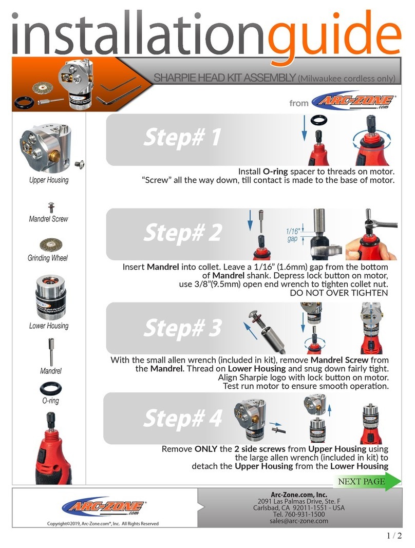
DIAQUIP QDS-150 User manual

DIAMOND DRILLING DRILL STANDS
QDS-150
QDS-350
QDS-500
QDS-800
OPERATORS MANUAL

/02 WWW.DIAQUIP.CO.UK
QDS-150 Model
150Ø
N/A
540
330 x 200 x 815
N/A
8.8
QDS-350 Model
350Ø
N/A
660
425 x 245 x 1005
N/A
18
TECHNICAL DATA
TECHNICAL DATA
Model
Capacity w/o extension spacers (mm)
Max. Capacity with extension spacers (mm)
Effective Stroke (mm)
Dimensions L x W x H (mm)
Add on : Other Rig Heights
Net Weight(kg)
60mm clamp bracket for
mounting hand-held drilling
motors. Bolts directly to the
standard mounting spacer.
QDS-150 MODEL QDS-350 MODEL
60MM CLAMP BRACKET
1. Column
2. Clamp Bolt
3. Crank Handle
(Mounts on either side and also doubles as
a wrench for theAngle Lock Clamp Bolt)
4. Guidance Roller
5. Buttress Bar
6. Base
7. Leveling Bolts
8. Cradle
9. Cradle Lock Bolt
10. Adjustable Roller Axle Bolts (on left side only)
11. Carriage Lock Lever
1
1
3
3
3
4
55
66
77
9
8
11
10
2
OPTIONAL FOR QDS-350, QDS-500 & QDS-800
4
9
8
2
10
11

WWW.DIAQUIP.CO.UK /03
QDS-500 Model
300Ø
100mm spacer = 500Ø
690 -1m mast option
1390 – 1.6m mast option
425 x 245 x 1005
1.6m Column (1390mm stroke)
18 - 1m mast option
QDS-800 Model
400Ø
100mm spacer = 600Ø
200mm spacer = 800Ø
760 – 1m mast option
1760 – 2m mast option
2260 – 2.5m mast option
555 x 275 x 1035
2m Column (1760mm stroke)
2.5m Column (2260mm stroke)
26.5 - 1m mast option
TECHNICAL DATA
TECHNICAL DATA
Model
Capacity w/o extension spacers (mm)
Max. Capacity with extension spacers (mm)
Effective Stroke (mm)
Dimensions L x W x H (mm)
Add on : Other Rig Heights
Net Weight(kg)
EXTENSION SPACERS
200mm 150mm 100mm 45mm
QDS-500 MODEL
1. Column
2. Clamp Bolt
3. Crank Handle
(Mounts on either side and also doubles as
a wrench for theAngle Lock Clamp Bolt)
4. Guidance Roller
5. Buttress Bar
6. Base
7. Leveling Bolts
8. Cradle
9. Cradle Lock Bolt
10. Adjustable Roller Axle Bolts (on left side only)
11. Carriage Lock Lever 10
1
2
3
4
5
6
8
7
3
9
11
1
3
3
4
5
6
7
8
2
9
10
11
QDS-800 MODEL
OPTIONAL FOR QDS-500 & QDS 800

/04 WWW.DIAQUIP.CO.UK
INTRODUCTION:
ORIGINAL INSTRUCTIONS: For your personal safety, read and understand before using.
Save these instructions for future reference
This drill stand is designed to mount diamond core drilling motors by using a suitable mounting
spacer. A standard 4 bolt mounting spacer is included with this stand. The drill stand guides
the motor and diamond core bit so that it is possible to drill perfectly straight cuts in a safe and
controlled manner.
The stand is also able to slant so that holes may be cored at an angle as required.
This stand must be securely fastened to the workpiece using a concrete anchor.
WARNING: Do not attempt to use this stand if the mounting system does not t perfectly
to the drilling motor.
MOUNTING THE MOTOR TO THE DRILL STAND
Rig-Mounted Type Motors:
If the drill motor is the 4 bolt rig-mounted type, the drill stand’s mounting spacer must be bolted
to the drill motor. The mounting tenon must t securely in the slot in the back of the drill motor,
then evenly tighten the four bolts. This mounting spacer now acts as a secure and accurate
coupling between the drill motor and the drill stand. The mounting spacer now ts in the dovetail
in the stand’s cradle and is secured by the cradle lock bolt.
Hand-Held Type Motors:
If the drill motor is the hand-held type, the clamp bracket must be used. The clamp bracket
must rst be bolted to the mounting spacer. Then the motor’s gearcase collar must be mounted
in the clamp bracket. Generally, the drill motor’s side handle will need to be rst removed. To
insert, rst loosen the clamp bracket using the crank handle as a wrench, then insert the motor,
turn to the desired orientation and then securely fasten the clamp bolt.
Now the assembly may be tted into the dovetail in the stand’s cradle and the cradle lock bolt
securely tightened.

WWW.DIAQUIP.CO.UK /05
EXTENSION SPACERS
For larger diameter core bits, extension spacers are required to maintain clearance between
the bit and the the stand. Extension spacers in sizes 45, 100, 150 and 200mm are optionally
available. These may also be stacked together as needed to acheive the required distance.
These mount to the cradle using two bolts and both bolts must be securely tightened. The
motor unit in turn mounts to the spacer
WARNING: Always ensure that all mounting fasteners are securely tightened.
WARNING: Never attempt to drill unless the stand is xed securely beyond any doubt.

/06 WWW.DIAQUIP.CO.UK
DRILLING STAND FUNCTIONAL DESCRIPTION
Fastening the drill rig
Once the desired position of the rig is determined, Use a concrete anchor to secure the rig.
Drill a suitable sized hole for the anchor with a hammer drill.
Drive in the anchor.
Use a long threaded rod with a large washer and nut to secure the base.
Before fully tightening the nut, use a spirit level to check if the stand is level. If needed, loosen
the locknuts and adjust the four leveling bolts to achieve levelness. Then retighten the locknuts.
Now fully tighten the securing nut which afxes the base to the work surface.
NOTE: We recommend using the optional Anchoring Plate for the most secure possible
xing of the base to the workpiece. Place the anchoring plate on the base with the
threaded rod through the hole. Then add the washer and nut. Tighten secularly.
(QDS-500 & QDS-800 only).
Note: If mounting on a wall, it is usually more convenient to secure the stand with the
motor head removed. Using the 19mm combination wrench, loosen the cradle lock bolt
on the carriage to lift the motor head up and away. Once the stand is xed, the motor
head may be re-installed on the stand. Be sure to securely tighten the cradle lock bolt(s).
Note: If additional security is needed, use the jackscrew with an appropriate length
bracing column between the opposite wall or ceiling dependent on where the rig is
situated. Be sure to risk assess the surrounding wall/ ceiling construction before using
this method of anchoring the rig.
ADJUSTING THE DRILLING ANGLE
The drilling angle can be tilted from 0 to 45 degrees. To adjust
the angle, use the crank handle as a wrench and loosen the
angle clamp bolt. Refer to the scale on the column indicating
the angle. Adjust to the desired angle and tighten the clamp.
CAUTION: Do not overtighten the clamp. Only tighten the
necessary amount to make the clamp secure. Overtightening
could distort the column.
0 to 45 degrees

WWW.DIAQUIP.CO.UK /07
CARRIAGE LOCK
Slide the carriage lock lever to the left to lock the carriage in
place. Slide the lever to the right to release the carriage. On
some models, the carriage lock is a thumb screw on the right
side of the carriage. Tighten to lock, loosen to release.
CAUTION: Hold the crank lever or motor head whenever
releasing the carriage lock. It could slam down causing
possible injury or damage to the bit or machine.
Carriage Lock Lever
REDUCTION GEARING
On the larger size stands, QDS-500,
QDS-800, there are two crank spindles:
one for standard cranking and one for reduced gear ratio
cranking. The reduced gear ratio allows the operator
to drill with greatly reduced effort when using large
diameter core bits. To switch from standard to reduced
gear ratio cranking, simply remove the crank handle
from the main spindle and connect to the forward spindle
on the left side.
Standard Ratio
Reduced Ratio
ADJUSTING THE DRILLING STAND GUIDANCE
Loose guidance will cause the bit to run out-of-true
and result in poor performance, sticking and possible
damage to the bit. If the rollers can be turned by hand
with the carriage locked, they are too loose.
To adjust the guidance, the two guide rollers on the left
side are on eccentric shafts. Turn the eccentric roller
axle bolt until the clearance is taken up on each roller
in turn. Turn just enough so that the roller cannot be
turned by hand. Now test the tightness of the carriage by
cranking it up and down. There should be no free-play,
yet no binding throughout its travel.
Adjustable Roller
Axle Bolts
Right side Roller Axle Bolts are not adjustable

/08 WWW.DIAQUIP.CO.UK
NOTES

WWW.DIAQUIP.CO.UK /09
NOTES

/10 WWW.DIAQUIP.CO.UK
NOTES

WWW.DIAQUIP.CO.UK /11
NOTES

APPROVED SERVICE CENTRE;
WWW.DIAQUIP.CO.UK
0161 406 0609
SALES@DIAQUIP.CO.UK
DIAQUIP HEAD OFFICE | MANCHESTER, UK
This manual suits for next models
3
Table of contents
Popular Power Tools Accessories manuals by other brands
SCHUNK
SCHUNK ROTA THW Series Translation of original operating manual
GRS
GRS 003-570 instructions
Milwaukee
Milwaukee 3000 Operator's manual
Kersten
Kersten WKB-H-K 35 Original operating instructions

Renfroe
Renfroe LPA Application, Operation and Maintenance Manual
Record Power
Record Power Coronet Hawk Original instruction manual
