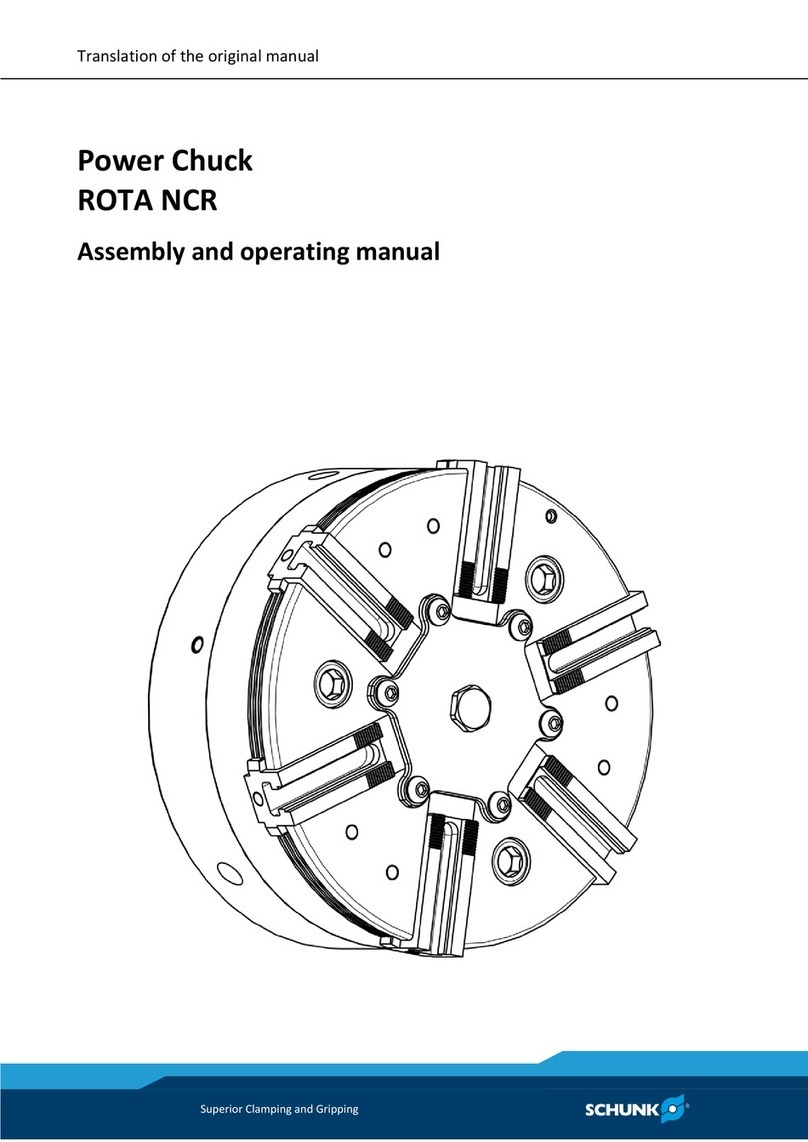
SCHUNK ROTA THW Series Operation manual

Translation of original operating manual
Power chuck
ROTA THW / THWB
Assembly and operating manual
Superior Clamping and Gripping

Imprint
2 02.00|ROTA THW / THWB |en
Imprint
Copyright:
This manual is protected by copyright. The author is SCHUNK GmbH & Co. KG. All rights
reserved. Any reproduction, processing, distribution (making available to third parties),
translation or other usage - even excerpts - of the manual is especially prohibited and re-
quires our written approval.
Technical changes:
We reserve the right to make alterations for the purpose of technical improvement.
Document number: 0889110
Version: 02.00 |16/10/2017|en
© SCHUNK GmbH & Co. KG
All rights reserved.
Dear Customer,
thank you for trusting our products and our family-owned company, the leading technol-
ogy supplier of robots and production machines.
Our team is always available to answer any questions on this product and other solutions.
Ask us questions and challenge us. We will find a solution!
Best regards,
Your SCHUNK team
SCHUNK GmbH & Co. KG
Spann- und Greiftechnik
Bahnhofstr. 106 – 134
D-74348 Lauffen/Neckar
Tel. +49-7133-103-0
Fax +49-7133-103-2399
schunk.com

Table of contents
02.00|ROTA THW / THWB |en
3
Table of contents
1
General .................................................................................................................... 5
1.1
About this manual .................................................................................................... 5
1.1.1
Presentation of Warning Labels.................................................................... 5
1.1.2
Applicable documents................................................................................... 6
1.1.3
Sizes............................................................................................................... 6
1.2
Warranty................................................................................................................... 6
1.3
Scope of delivery ...................................................................................................... 6
2
Basic safety notes .................................................................................................... 7
2.1
Intended use............................................................................................................. 7
2.2
Not intended use ...................................................................................................... 7
2.3
Constructional changes ............................................................................................ 7
2.4
Spare parts................................................................................................................ 8
2.5
Chuck jaws ................................................................................................................ 8
2.6
Environmental and operating conditions................................................................. 9
2.7
Personnel qualification............................................................................................. 9
2.8
Personal protective equipment.............................................................................. 10
2.9
Notes on safe operation......................................................................................... 10
2.10
Transport ................................................................................................................ 11
2.11
Malfunctions........................................................................................................... 11
2.12
Disposal................................................................................................................... 11
2.13
Fundamental dangers............................................................................................. 11
2.13.1
Protection during handling and assembly .................................................. 12
2.13.2
Protection during commissioning and operation ....................................... 12
2.13.3
Protection against dangerous movements................................................. 12
2.13.4
Notes on particular risks ............................................................................. 13
3
Technical data ......................................................................................................... 17
3.1
Chuck data .............................................................................................................. 17
3.2
Clamping force / speed diagrams........................................................................... 18
3.3
Calculations for clamping force and speed ............................................................ 22
3.3.1
Calculation of the required clamping force in case of a given rpm............ 22
3.3.2
Calculation example: required initial clamping force for a given speed .... 24
3.3.3
Calculation of the permissible speed in case of a given initial
clamping force............................................................................................. 25
3.4
Grades of Accuracy................................................................................................. 26
3.5
Permissible imbalance............................................................................................ 26
3.6
Torques per screw .................................................................................................. 27

Table of contents
4 02.00|ROTA THW / THWB |en
4
Function .................................................................................................................. 28
4.1
Function of the chuck ............................................................................................. 28
4.2
Functional testing ................................................................................................... 28
4.3
Handling the chuck and the base jaws................................................................... 29
4.4
Base jaw position.................................................................................................... 30
4.5
Exchanging and turning the top jaws ..................................................................... 30
5
Transport ................................................................................................................ 31
6
Mounting ................................................................................................................ 32
6.1
Installing and connecting ....................................................................................... 32
6.2
Mounting the chuck onto the machine spindle ..................................................... 32
7
Maintenance ........................................................................................................... 35
7.1
Lubrication.............................................................................................................. 35
7.2
Maintenance intervals............................................................................................ 36
7.3
Technical condition ................................................................................................ 36
7.4
Disassembly and assembly of the chuck ................................................................ 36
8
Chuck mounts and Spare parts ................................................................................ 38
8.1
Chuck mounts......................................................................................................... 38
8.2
Spare parts.............................................................................................................. 39
9
Drawings ................................................................................................................. 40
10
Translation of the original declaration of incorporation........................................... 43
11
Appendix on Declaration of Incorporation, as per 2006/42/EC, Annex II, No. 1 B ..... 44

General
02.00|ROTA THW / THWB |en
5
General
About this manual
This manual contains important information for a safe and appro-
priate use of the product.
This manual is an integral part of the product and must be kept
accessible for the personnel at all times.
Before starting work, the personnel must have read and under-
stood this operating manual. Prerequisite for safe working is the
observance of all safety instructions in this manual.
Illustrations in this manual are provided for basic understanding
and may differ from the actual product design.
In addition to these instructions, the documents listed under
(1.1.2, Page 6) are applicable.
Presentation of Warning Labels
To make risks clear, the following signal words and symbols are
used for safety notes.
DANGER
Danger for persons!
Non-observance will inevitably cause irreversible injury or death.
WARNING
Dangers for persons!
Non-observance can lead to irreversible injury and even death.
CAUTION
Dangers for persons!
Non-observance can cause minor injuries.
NOTICE
Material damage!
Information about avoiding material damage.
1
1.1
1.1.1

General
6 02.00|ROTA THW / THWB |en
Applicable documents
• General terms of business*
• Catalog data sheet of the purchased product *
• Calculation of the jaw centrifugal forces, "Technology" chapter
in the lathe chuck catalog *
The documents marked with an asterisk (*) can be downloaded on
our homepage schunk.com
Sizes
This operating manual applies to the following sizes:
• ROTA THW
400; 500; 630; 800; 1000
• ROTA THWB
210; 265; 315; 400; 500; 630
Warranty
The warranty period is 24 months after delivery date from factory
or 500 000 cycles*, if it is used as intended, under the following
conditions:
• Observe the applicable documents (1.1.2, Page 6)
• Observe the ambient conditions and operating conditions,
(2.6, Page 9)
• Observe the specified maintenance and lubrication intervals,
(7, Page 35)
Parts touching the workpiece and wear parts are not included in
the warranty.
* A cycle consists of a complete clamping process ("Open" and
"Close").
Scope of delivery
1
Power chuck incl. Fastening screws
- Base jaws with screws
- Jaw change wrench
1
Eye bolt
1
Operating manual
1.1.2
1.1.3
1.2
1.3

Basic safety notes
02.00|ROTA THW / THWB |en
7
Basic safety notes
Intended use
This product is intended for clamping workpieces on machine tools
and other suitable technical devices.
• The product may only be used within the scope of its technical
data, (3, Page 17).
• The product is intended for industrial and industry-oriented
use.
• Appropriate use of the product includes compliance with all
instructions in this manual.
• The maximum RPM of the chuck and the required clamping
force must be determined by the user for the respective
clamping task based on the applicable standards and technical
specifications of the manufacturer.
(See also “Calculations for clamping force and RPM” in the
chapter “Technical data”). (3, Page 17)
Not intended use
A not intended use of the product is for example:
• It is used as a press, a punch, a toolholder, a load-handling
device or as lifting equipment.
• the product is used for unintended machines or workpieces.
• the technical data is exceeded when using the product. (3,
Page 17)
• if workpieces are not clamped properly, paying particular
attention to the clamping forces specified by the manufacturer.
• if it is used in working environments that are not permissible.
• if the product is operated without a protective cover.
Constructional changes
Implementation of structural changes
By conversions, changes, and reworking, e.g. additional threads,
holes, or safety devices can impair the functioning or safety of the
product or damage it.
2
2.1
2.2
2.3

Basic safety notes
8 02.00|ROTA THW / THWB |en
• Structural changes should only be made with the written
approval of SCHUNK.
Spare parts
Use of unauthorized spare parts
Using unauthorized spare parts can endanger personnel and
damage the product or cause it to malfunction.
• Use only original spare parts or spares authorized by SCHUNK.
Chuck jaws
Requirements of the chuck jaws
Stored energy can make the product unsafe and risk the danger of
serious injuries and considerable material damage.
• Only replace chuck jaws if no residual energy can be released.
• Do not use welded jaws.
• The jaws should be designed as light and as low as possible.
The clamping point must be as close as possible to the chuck
face (clamping points at a greater distance lead to greater
surface pressure in the jaw guidance and can significantly
reduce the clamping force).
• If for constructional reasons the special chuck jaws are heavier
than the top jaws assigned to the lathe chuck, greater centrifu-
gal forces must be accounted for when defining the required
clamping force and the recommended speed.
• The maximum recommended speed may only be operated in
conjunction with maximum actuating force and only with the
lathe chuck in optimal, fully functioning condition.
• After a collision, the lathe chuck and the chuck jaws must be
subjected to a crack test before being used again. Damaged
parts must be replaced with original SCHUNK spare parts.
• Screw the jaw mounting screws into the bore holes furthest
apart.
• The jaw fastening screws must be replaced if they show any
signs of wear or damage. Only use screws with a quality of 12.9.
2.4
2.5

Basic safety notes
02.00|ROTA THW / THWB |en
9
Environmental and operating conditions
Required ambient conditions and operating conditions
Incorrect ambient and operating conditions can make the product
unsafe, leading to the risk of serious injuries, considerable material
damage and/or a significant reduction to the product's life span.
• Make sure that the product is used only in the context of its de-
fined application parameters, (3, Page 17).
• Make sure that the product is a sufficient size for the applica-
tion.
• Only use high-quality cooling emulsions with anti-corrosive ad-
ditives during processing.
• Lubricating intervals must be adhered to (7.2, Page 36).
Personnel qualification
Inadequate qualifications of the personnel
If the personnel working with the product is not sufficiently quali-
fied, the result may be serious injuries and significant property
damage.
• All work may only be performed by qualified personnel.
• Before working with the product, the personnel must have read
and understood the complete assembly and operating manual.
• Observe the national safety regulations and rules and general
safety instructions.
The following personal qualifications are necessary for the various
activities related to the product:
Due to their technical training, knowledge and experience, trained
electricians are able to work on electrical systems, recognize and
avoid possible dangers and know the relevant standards and regu-
lations.
Due to its technical training, knowledge and experience, qualified
personnel is able to perform the delegated tasks, recognize and
avoid possible dangers and knows the relevant standards and
regulations.
Instructed persons were instructed by the operator about the
delegated tasks and possible dangers due to improper behaviour.

2.6
2.7
Trained electrician
Qualified personnel
Instructed person

Basic safety notes
10 02.00|ROTA THW / THWB |en
Due to its technical training, knowledge and experience, service
personnel of the manufacturer is able to perform the delegated
tasks and to recognize and avoid possible dangers.
Personal protective equipment
Using personal protective equipment
Not wearing personal protective equipment while working with
the product, may result in dangers that impact the personnel's
safety and health.
• While working with the product, observe the health and safety
regulations and wear the required personal safety equipment.
• Observe the valid safety and accident prevention regulations.
• In case of sharp edges and corners and rough surfaces, wear
protection gloves.
• In case of hot surfaces, wear heat-resistant protection gloves.
• When dealing with hazardous substances, wear protection
gloves and goggles.
• In case of moving parts, wear tight protection clothes.
Notes on safe operation
Incorrect handling of the personnel
Incorrect handling and assembly may impair the product's safety
and cause serious injuries and considerable material damage.
• Avoid any manner of working that may interfere with the
function and operational safety of the product.
• Use the product as intended.
• Observe the safety notes and assembly instructions.
• Do not expose the product to any corrosive media. This does
not apply to products that are designed for special environ-
ments.
• Eliminate any malfunction immediately.
• Observe the care and maintenance instructions.
• Observe the current safety, accident prevention and environ-
mental protection regulations regarding the product's appli-
cation field.
Service personnel of
the manufacturer
2.8
2.9

Basic safety notes
02.00|ROTA THW / THWB |en
11
Transport
Handling during transport
Incorrect handling during transport may impair the product's
safety and cause serious injuries and considerable material damage.
• When handling heavy weights, use lifting equipment to lift the
product and transport it by appropriate means.
• Secure the product against falling during transportation and
handling.
• Stand clear of suspended loads.
Malfunctions
Behavior in case of malfunctions
• Immediately remove the product from operation and report
the malfunction to the responsible departments/persons.
• Order appropriately trained personnel to rectify the malfunction.
• Do not recommission the product until the malfunction has
been rectified.
• Test the product after a malfunction to establish whether it still
functions properly and no increased risks have arisen.
Disposal
Handling of disposal
The incorrect handling of disposal may impair the product's safety
and cause serious injuries as well as considerable material and
environmental harm.
• Follow local regulations on dispatching product components for
recycling or proper disposal.
Fundamental dangers
General
• Observe safety distances.
• Never deactivate safety devices.
• Before commissioning the product, take appropriate protective
measures to secure the danger zone.
• Disconnect power sources before installation, modification,
maintenance, or calibration. Ensure that no residual energy
remains in the system.
2.10
2.11
2.12
2.13

Basic safety notes
12 02.00|ROTA THW / THWB |en
• If the energy supply is connected, do not move any parts by
hand.
• Do not reach into the open mechanism or movement area of
the product during operation.
Protection during handling and assembly
Incorrect handling and assembly
Incorrect handling and assembly may impair the product's safety
and cause serious injuries and considerable material damage.
• Have all work carried out by appropriately qualified personnel.
• For all work, secure the product against accidental operation.
• Observe the relevant accident prevention rules.
• Use suitable assembly and transport equipment and take
precautions to prevent jamming and crushing.
Incorrect lifting of loads
Falling loads may cause serious injuries and even death.
• Stand clear of suspended loads and do not step into their
swiveling range.
• Never move loads without supervision.
• Do not leave suspended loads unattended.
Protection during commissioning and operation
Falling or violently ejected components
Falling and violently ejected components can cause serious injuries
and even death.
• Take appropriate protective measures to secure the danger
zone.
• Never step into the danger zone during operation.
Protection against dangerous movements
Unexpected movements
Residual energy in the system may cause serious injuries while
working with the product.
• Switch off the energy supply, ensure that no residual energy
remains and secure against inadvertent reactivation.
2.13.1
2.13.2
2.13.3

Basic safety notes
02.00|ROTA THW / THWB |en
13
• Never rely solely on the response of the monitoring function to
avert danger. Until the installed monitors become effective, it
must be assumed that the drive movement is faulty, with its
action being dependent on the control unit and the current
operating condition of the drive. Perform maintenance work,
modifications, and attachments outside the danger zone
defined by the movement range.
• To avoid accidents and/or material damage, human access
to the movement range of the machine must be restricted.
Restrict unintentional access by persons to this range e.g. via
a protective cover, protective fence or photoelectric barrier.
The protective cover and protective fence must be rigid enough
to withstand the maximum possible movement energy.
EMERGENCY STOP switches must be easily and quickly accessi-
ble. Check the function of the EMREGENCY STOP before start-
ing up the machine or system. If this protective equipment is
not working properly, prevent the operation of the machine.
Notes on particular risks
DANGER
Risk of fatal injury from suspended loads!
Falling loads can cause serious injuries and even death.
• Use suitable lifting equipment.
• Secure the product to prevent it from falling.
• Stand clear of suspended loads and do not step within their
swiveling range.
• Only move loads when supervised and do not leave
unattended.
• Wear suitable protective equipment.
2.13.4

Basic safety notes
14 02.00|ROTA THW / THWB |en
DANGER
Risk of fatal injury to operating personnel due to the workpiece
falling down or being flung out in the event of a power failure
In the event of a power failure, the lathe chuck's clamping force
may fail immediately and the workpiece may be released in an
uncontrolled manner. This poses a risk of death or injury to the
operating personnel and can result in serious damage to the
automated system.
• The machine manufacturer and the operator of the machine
must carry out and document a hazard assessment and risk
analysis to ensure that suitable measures are taken to main-
tain the lathe chuck's clamping force until the machine comes
to a standstill and the workpiece can be secured (e.g. using a
crane or suitable lifting equipment).
• The machines and equipment must fulfill the minimum
requirements of the EC Machinery Directive; specifically, they
must have effective technical measures to protect against
potential mechanical hazards.
DANGER
Possible risk of fatal injury to operating personnel if a jaw
breaks or if the lathe chuck fails because the technical data have
been exceeded and a workpiece is released or parts fly off
• The technical data specified by the manufacturer for using the
lathe chuck must never be exceeded.
• The lathe chuck may only be used on machines and facilities
that fulfill the minimum requirements of the EC Machinery
Directive; specifically, they must have effective technical
measures to protect against possible mechanical hazards.

Basic safety notes
02.00|ROTA THW / THWB |en
15
DANGER
Possible risk of fatal injury to operating personnel from clothing
or hair being caught on the lathe chuck and being dragged into
the machine
Loose clothing or long hair may become caught on projecting
parts of the lathe chuck and be drawn into the machine.
• The machines and equipment must fulfill the minimum re-
quirements of the EC Machinery Directive; specifically, they
must have effective technical measures to protect against
potential mechanical hazards.
• Always wear tight-fitting clothing and a hairnet when working
on the machine and the lathe chuck.
CAUTION
Danger of slipping and falling in case of dirty environment
where the chuck is used (e.g. by cooling lubricants or oil).
• Ensure that the working environment is clean before starting
assembly and installation work.
• Wear suitable safety shoes.
• Follow the safety and accident-prevention regulations when
operating the chuck, especially when working with machine
tools and other technical equipment.
CAUTION
Danger of limbs being crushed by opening and closing of the
chuck jaws during manual loading and unloading or when re-
placing moving parts.
• Do not reach between the chuck jaws.
• Automatic loading is preferred.
• If manual loading is used, adjust the jaw position so that the
opening gap between the jaw and the workpiece is less than
4 mm.
• Wear protective gloves.
• Observe the safety and accident prevention regulations during
operation of the chuck, especially in connection with machin-
ing centers and other technical equipment.

Basic safety notes
16 02.00|ROTA THW / THWB |en
CAUTION
Risk of burns due to workpieces with high temperatures.
• Wear protective gloves when removing the workpieces.
• Automatic loading is preferred.
CAUTION
Danger of damage due to incorrectly selected clamping position
of the clamping jaws to the workpiece.
An incorrectly selected clamping position of the clamping jaws to
the workpiece can result in damage to the base and top jaws.
• Make sure that the workpiece clamping is concentric.
• In the case of a chuck with a quick-change jaw system the top
jaws must not protrude radially beyond the base jaws used.
Exception: The supporting jaw variant 3 protrudes beyond the
chuck base jaw due to the construction of the jaw. In this case,
the T-nuts must always be inserted completely into the groove
of the chuck base jaw.
CAUTION
Hazard from vibration due to imbalanced rotating parts and
noise generation.
Physical and mental strains due to imbalanced workpieces and
noise during the machining process on the clamped and rotating
workpiece.
• Ensure the chuck's axial and concentric runout.
• Check options for remedying imbalances on special top jaws
and workpieces.
• Reduce the speed.
• Wear hearing protection.

Technical data
02.00|ROTA THW / THWB |en
17
Technical data
Chuck data
ROTA THW
400
500
630
800 - 1000
Max. actuating force [kN]
133
133
133
On request
Max. clamping force [kN]
240
240
240
Max. rotation speed [min-1]
3500
2200
1700
Stroke per jaw [mm]
6.5
9
9.8
Piston stroke [mm]
23
30
34
Through hole [mm]
120
128
160
Operating temperature
15°C - 60°C
Centrifugal torque of the base
jaw McGB [kgm]
For the NCX chuck, it is necessary to specifically determine
this data. Examples of calculation can be found in the
"Technology" chapter of the SCHUNK lathe chuck catalog
and in the "Chuck jaws in special design/technology"
chapter of the SCHUNK chuck jaws catalog. These catalogs
can be downloaded from schunk.com .
Max. jaw eccentricity of
center of gravity in axial
direction amax [mm]
ROTA THWB
210
265
315
400
500
630
Max. actuating force [kN]
50
73
100
133
133
133
Max. clamping force [kN]
90
132
180
240
240
240
Max. rotation speed [min-1]
3000
3000
2800
2450
1600
240
Stroke per jaw [mm]
5.7
6.5
6.5
6.5
9
6.5
Piston stroke [mm]
20
23
23
23
30
34
Through hole [mm]
52
71
86
120
128
160
Operating temperature
15°C - 60°C
Centrifugal torque of the
base jawMcGB [kgm]
For the NCX chuck, it is necessary to specifically determine
this data. Examples of calculation can be found in the
"Technology" chapter of the SCHUNK lathe chuck catalog
and in the "Chuck jaws in special design/technology"
chapter of the SCHUNK chuck jaws catalog. These catalogs
can be downloaded from schunk.com .
Max. jaw eccentricity of cen-
ter of gravity in axial direc-
tion amax [mm]
The maximum permissible speed for special machining has to be
defined by the user on the basis of the required clamping forces.
This speed must not exceed the maximum speed of the chuck.
3
3.1

Technical data
18 02.00|ROTA THW / THWB |en
Ensure minimal weight for all jaws.
For unhardened top jaws or chuck jaws in special design, the per-
missible RPM according to VDI 3106 must be calculated for the re-
spective machining job. Whereby the recommended maximum
speed must not be exceeded. The values calculated must be
checked by means of dynamic measurement using a clamping
force tester.
Clamping force / speed diagrams
The diagrams refer to 3-jaw-chuck.
Clamping force/speed curves were determined with hard standard
stepped jaws SHB, SWB and SWB-AL. The maximum actuating
force was introduced and the jaws were placed flush with the base
jaw outer edge.
The chuck is in perfect condition and lubricated with SCHUNK LINO
MAX special grease.
Should one or several of the above mentioned parameters be
changed the diagrams are no longer valid.
Chuck set-up for clamping force / speed diagram
F/3
Clamping force per jaw
S
Center of gravity
rs
Center of gravity radius
a
max
Max. jaw eccentricity of
center of gravity in axial
direction
F
max
Max. actuating force
3.2

Technical data
02.00|ROTA THW / THWB |en
19
Clamping force / speed diagrams ROTA THW 400-120
Clamping force / speed diagrams ROTA THW 500-128
Clamping force / speed diagrams ROTA THW 630-160

Technical data
20 02.00|ROTA THW / THWB |en
Clamping force / speed diagrams ROTA THWB 210-52
Clamping force / speed diagrams ROTA THWB 265-71
Clamping force / speed diagrams ROTA THWB 315-86
This manual suits for next models
12
Table of contents
Other SCHUNK Power Tools Accessories manuals

SCHUNK
SCHUNK ROTA TPS-K Series User instructions

SCHUNK
SCHUNK HSK 40 User manual

SCHUNK
SCHUNK ROTA NCR-A 190 User instructions

SCHUNK
SCHUNK ROTA TB-TBS-EP User instructions

SCHUNK
SCHUNK TENDO ES User instructions

SCHUNK
SCHUNK Tendo Turn User manual

SCHUNK
SCHUNK ROTA NCR Series User instructions

SCHUNK
SCHUNK TENDO E compact HSK-A63 User instructions