Renfroe LPA Installation guide

WARNING:
Before putting tool in service,
take to your immediate
supervisor.
Model LPA Clamp
Application, Operation and Maintenance Manual
OMLPA115
RENFROE
Model LPA

This Operator’s Manual covers the Application, Operation
and Maintenance of this RENFROE product. Operator’s
Manuals for other current RENFROE products are available
upon request. Direct requests to J.C. Renfroe & Sons Jack-
sonville, Florida 32201.
Operators
Manual
J.C. RENFROE & SONS
of Jacksonville, Florida, has
been an international leader
in the manufacture and mar-
keting of Lifting Clamps for
over fifty years. RENFROE
products are manufactured
in Jacksonville, Florida. A
worldwide network of stock-
ing distributors provides a
readily available source of
supply and service.
J.C. RENFROE & SONS
Jacksonville, Florida 32201
Telephone: 904/356-4181
Toll Free: 1-800-874-8454
Fax: 904/354-7865
www.jcrenfroe.com
Copyright © 2001 J.C. Renfroe & Sons

THIS PUBLICATION SUPERSEDES ALL
PREVIOUSLY PUBLISHED AND/OR DISTRIBUTED
INFORMATION BY MANUFACTURER AND/OR ITS
DISTRIBUTORS WITH RESPECT TO APPLICABLE
RENFROE PRODUCTS AND SUBJECT MATTER
DESCRIBED OR CONTAINED HEREIN.
NOTICE OF EXCLUSION OF WARRANTY
RENFROE HAS HEREIN SET FORTH IN
CONSPICUOUS LANGUAGE AN EXCLUSION
OF ANY WARRANTY EITHER EXPRESSED OR
IMPLIED, WHICH IS NOT SPECIFICALLY AND
PARTICULARLY CONTAINED HEREIN.
PLEASE REFER TO THAT STATEMENT FOR
REPRESENTATIONS AND WARRANTIES OF
PRODUCTS MANUFACTURED BY J.C.
RENFROE & SONS
WARNING:
Prior to selection, operation and/or maintenance
of RENFROE products, read and understand the infor-
mation provided in this manual.
The understanding and use of the Definitions are
important in determining the limitations and proper appli-
cation of RENFROE products.
Failure to review and utilize recommended appli-
cations, operation and maintenance instructions may
result in serious injury to operator and others.


OPERATING AIDS
(DO’S AND DON’TS)
1. DO read and understand the Operators Manual before using the clamp
2. DO Consult Operator’s Manual or RENFROE when in doubt.
3. DON’T Lift over workmen DON’T lift over Safety Areas or personnel.
4. Do attend a factory training class for establishing proper use of Renfroe
Products.
5. DO Lock clamp closed before lifting load. DON’T lift with lock in open or
“Lock Open” position.
6. DON’T Use a connection that may release the clamp.
7. DON’T attach clamp directly to crane hook. DO use a flexible connection
between crane and clamp shackle. DON’T use heavy flexible connection.
8. DO use correct clamp for job. DON’T use large capacity clamps to lift light
loads.
9. DO Use an adequate number of clamps to balance load. DON’T lift loads
that are not balanced.
10. DO Use clamps within their rated capacity. DON’T overload clamps
11. DO Inspect clamp before each lift, follow inspection and maintenance in-
structions outlined in this manual and use RENFROE replacement parts to
assure proper operation of the clamp
12. DON’T Use clamp that has been overloaded. DO refer to pre-lift inspection
in Operators Manual
13. DON’T Side load with a straight shackle clamp. DON’T lift from side with
vertical clamp
14. DON’T Misuse. DON’T lift plate from bottom of plate stack.
15. DON’T Rush. DON’T lift more than one plate at a time with a vertical clamp.
16. DON’T Improvise. Always use correct clamp for job. DON’T lift plate hori-
zontally with a vertical lift only clamp.
17. DON’T Alter clamp. DON’T grind, weld or modify the clamp in any manner.

DEFINITIONS
VERTICAL LIFT: The lifting of a single
plate or member in which the lifting
force exerted by the rigging is directly
above and in line with the lifting shackle
as shown in the illustration below.
VERTICAL TURN/LIFT: A vertical turn/
lift clamp is a vertical lifting clamp spe-
cifically intended to turn a single plate or
member thru a ninety degree (90°) arc
and back to vertical thru the same nine-
ty degree (90°) arc or from horizontal to
vertical to horizontal thru a one hundred
and eighty degree (180°) arc. Refer to
Application Section of specific Turn/Lift
clamps for further detail. During the
turning operation the edge of the plate
opposite the edge to which the clamp is
attached should always be in contact
with a supporting surface such as a fac-
tory floor and the load on the clamp not
exceed one half rated capacity of
clamp—refer to illustrations shown be-
low.
STEEL PLATES: Unless otherwise
specified, lifting clamps are manufac-
tured to handle hot-rolled steel plates
whose Brinell Hardness does not ex-
ceed 300.
WARNING: Do not lift plates with
coatings or mill scale that prevent
the gripping surfaces of the clamp
from making positive contact with
the base metal.
For applications not covered by the
above information, secure written rec-
ommendations from RENFROE.
FINISHED AND POLISHED PLATES:
Steel plates in this category have other
than hot-rolled surfaces such as stain-
less steel, etc., are generally handled
using non-marring clamps incorporat-
ing smooth gripping surfaces.
STRUCTURAL MEMBERS—
FABRICATED SECTIONS: Unless oth-
erwise specified, clamps described as
capable of handling structural mem-
bers and fabricated sections are limited
to hot-rolled steel whose Brinell Hard-
ness does not exceed 300.
WARNING: For applications not cov-
ered by the above information, se-
cure written recommendations from
RENFROE.

RATED CAPACITY: The rated capaci-
ty of a RENFROE product is based on
the product being in “new or as new”
condition and represents the maximum
load the product is to be subjected to
when utilized in the manner described
in this manual. Wear, misuse, abuse
and other factors relating to usage may
reduce the rated capacity. Shock load-
ing and the factors listed must be taken
into consideration when selecting a
RENFROE product for a given applica-
tion.
PLATE THICKNESS: The minimum
and maximum plate thickness a clamp
specified for handling plates is capable
of lifting.
WARNING: Never use a clamp for
lifting a plate where the plate thick-
ness is less than or greater than the
minimum and maximum stenciled
on the clamp.
JAW OPENING: The minimum and
maximum thickness of a member of
clamp specified as having a JAW
OPENING is capable of handling
WARNING: Never use a clamp on a
member whose thickness is less
than or greater than the range of jaw
opening stenciled on the clamp.
OPERATING TEMPERATURES: Un-
less specified under the Application
Section of the individual model, the
approved operating temperature of
RENFROE clamps is from zero de-
grees Fahrenheit (-18 Celsius) to a
maximum of 200 degrees Fahrenheit
(+93 degrees Celsius). The minimum
and maximum temperatures apply to
both ambient and the material being
handled by the clamp.
WARNING: Secure written authori-
zation from RENFROE before using
clamps in temperatures other than
shown.
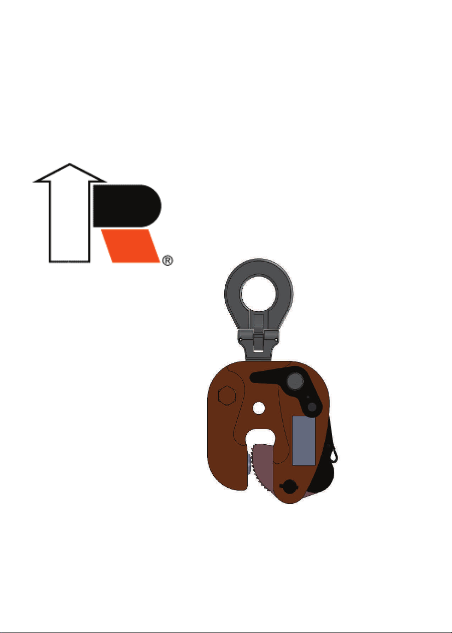
“LOCK OPEN-LOCK CLOSED” - an
over-center spring loaded mechanism
in which the spring exerts a force on
the gripping cam when the lock handle
is moved to the “Lock Closed” position.
When the handle is moved to the “Lock
Open” the gripping cam is maintained
in the retracted position for ease in in-
stalling the clamp on a plate or mem-
ber. Refer to the Operation Section of
specific models of the “Lock Open-
Lock Closed” clamps for additional de-
tails. Typical “Lock Open-Lock Closed”
clamps are Models FRD, R, S, SD,
SEA, TL, TLA and the L-Series.
WARNING: A pointing out and notice
of danger. The purpose of a
“WARNING” is to apprise the operator
and all other affected persons of the
existence of danger of which he should
be but may not be aware and to enable
the operator to protect himself and oth-
ers where applicable against such dan-
ger. An attempt is made herein to warn
against reasonable and reasonably
foreseeable danger in the proper use
and possible reasonable misuse of
RENFROE products described in this
manual.

DESIGNATED PERSON — A person
selected by the employer or the em-
ployer’s representative as being com-
petent to perform those specific duties.
QUALIFIED PERSON — A person
who, by possession of a recognized
degree in an applicable field or certifi-
cate of professional standing, or who,
by extensive knowledge, training, and
experience, has successfully demon-
strated the ability to solve problems
relating to the subject matter at hand.

Application LPA
The model LPA has a lock open and lock closed feature built into its
design. The LPA has an auxiliary lock. The LPA clamp is recommend-
ed for turning of a single steel plate from horizontal to vertical to hori-
zontal through a hundred and eighty degree arc. Refer to Illustration A.
The Auxiliary lock prevents the lock handle from moving from the
“Lock Closed” position until the auxiliary lock button is manually de-
pressed. The “Lock Open” “Lock Closed” feature facilitate attaching
and removing the clamp from the plate. Refer to Definition Pages for
explanation of “Lock Open” “Lock Closed” clamp. A pivoting shackle is
included on the LPA clamp.
Refer to Illustration B.
WARNING: Refer to Load Chart showing de-rating of rated capaci-
ty based on angle of side loading.
For identification of component parts, refer to exploded view of clamp
located at the end of the Maintenance Section.
Model LPA

WARNING: When turning a plate from horizontal to vertical, the
operator must position the clamp at the start of the turning opera-
tion so that the lock handle is on the topside of the plate when the
plate is in the horizontal position. It should be noted at the finish
of a 180 degree turn that the lock handle will be on the underside
of the plate and therefore sufficient clearance under the plate
should be allowed for the lock to be disengaged. Refer to the sec-
tions on Operation and Maintenance for the approved procedures
in the Operation and Maintenance of this product.
Illustration A
Illustration B

OPERATION LPA
Step 1.
Before using any RENFROE clamp, refer to the Application Section to
confirm that the operation to be undertaken is an appropriate applica-
tion for this product.
Step 2.
Select appropriate capacity and plate thickness. The model designa-
tion, capacity and plate thickness are stenciled on each clamp.
WARNING: Never exceed rated capacity or use on plates that are
not within the range of plate thickness stenciled on the clamp.
Lift only one plate on each lift.
Always use a clamp with maximum plate thickness and rated capacity
near equal to the thickness and weight of the plate being lifted.
Step 3.
Inspect clamp before each lift.
WARNING: Do not use if in need of repair.
A. Check the clamp to be certain the identification and warn-
ing tags are present and legible.
B. Do not use the clamp if the tags are missing or illegible.
C. Inspect gripping surfaces for wear and defects. Gripping surfaces
must be sharp and free of foreign matter.
D. Inspect condition of body for wear, damage and distortion, particu-
larly in the area of the jaw opening.
E. Inspect lifting shackle and all pins for wear and damage.
F. Lock spring must have definite amount of tension when the lock is
moved to the “Lock Closed” position without material in the clamp.
Lock Pawl must rest on body spacer sleeve.
G. On the model LPA the auxiliary lock button must have a positive
spring action that projects it out to engage the lock handle when
the handle is moved to the “Lock Closed” position.
H. Remove from service any clamp in need of repair.

AUXILIARY LOCK
The Auxiliary Lock Release Button is mounted in the Lock Handle.
When Lock Handle is in “Lock Closed” position the Auxiliary Lock Re-
lease Button is flush with the top of the Lock Handle.
WARNING: Do not use clamp unless auxiliary lock is fully en-
gaged and auxiliary push button is flush with top of lock handle.
The Lock Button for the Auxiliary Lock is spring loaded and is mounted
in the clamp body.
WARNING: Do not use clamp unless lock button spring extends
button to fully engage auxiliary release button when lock handle
is in “Lock Closed” position.
Illustration C

Step 4.
The clamp is a component of the rigging used in lifting or transporting
a plate. It is important to use safe and adequate rigging. The lock is
used to hold the clamp in place until the gripping mechanism is actuat-
ed by a force applied to the lifting shackle.
WARNING: Improper or excessively heavy rigging may interfere
with the operation of the clamp and its ability to maintain a proper
position on the plate. Never attach crane hook directly to the
clamp—always use a flexible sling between crane hook and
clamp.
Step 5.
Move the lock lever to the “Lock Open” position. Gripping cam is main-
tained in retracted position. Refer to illustrations C and D.
Illustration D

Step 6.
Position clamp on plate being lifted.
Do not allow inside of jaw opening to rest on edge of plate. Maintain
1/4” clearance. Refer to Illustration C and D, Step 5.
Position clamp so direction of force applied by the crane is the capabil-
ity of the lifting shackle. Model LPA refer to De-rated Capacities Chart.
Step 7.
Make certain the gripping surfaces of the clamp are fully in contact
with the plate, and not partially on and off the edge of the plate.
Step 8.
Place the lock lever in the “Lock Closed” position. Lock Pawl must rest
on body spacer sleeve. Spring now exerts force on gripping cam. On
model LPA make certain the auxiliary lock button projects from the
housing and fully engages the lock handle. Refer to Illustration M
WARNING: Lift only when clamp is in “Lock Closed” position.
Step 9.
Commence lift.
WARNING: The operator should position himself away from the
fully clear of the member to be lifted. Plates being turned have a
tendency to slide. Do not commence lift until all personnel are
clear of the area of the lift. Never stand under or near a member
being lifted, lowered or moved.
Refer to Photograph L.

Step 10.
To remove clamp: after plate is fully supported and at rest in a stable
position, relax lifting force, keeping hands clear (depress auxiliary lock
button on LPA) move lock handle to “Lock Open” position. Lift clamp
from plate. Refer to Illustrations C and D, Step 5.
Step 11.
Inspect clamp. Remove from service if in need of repair.
WARNING: In the event the stenciling is worn and not legible or
the tag containing the model, capacity and other pertinent infor-
mation is missing—do not use clamp until it has been properly la-
beled. Renfroe will replace tag at no charge upon request.
Inspection kits are available at no charge upon request from the distrib-
utor or RENFROE.
Kit contains:

Maintenance Program for Renfroe Clamps Manufactured from Steel
The severity of service to which the clamp is subjected in the work place
determines the frequency and type of inspection procedure required for
the clamp. The frequency and type of inspection is determined by the
clamp owner. Renfroe acknowledges the ASME B30.20 safety standard
which sets forth minimum inspection requirements for “Below-the-Hook”
lifting devices and the Renfroe Recommended Inspection Schedule
meets and/or exceeds the ASME inspection recommendations.
Before using a clamp operators should be trained by a qualified
person to visually inspect a lifting clamp that will include but not be
limited to the following:
Every lift Inspection:
A visual inspection by the operator before and after each lift made by the
clamp.
A. Check the clamp to be certain the identification and
warning tags are present and legible.
B. Do not use the clamp if the tags are missing or illegible.
C. Inspect gripping surfaces for wear and defects. Gripping sur-
faces must be sharp and free of foreign matter.
D. Inspect condition of body for wear, damage and distortion,
particularly in the area of the jaw opening.
E. Inspect lifting shackle and all pins for wear and damage.
F. Lock spring must have definite amount of tension when the
lock is moved to the “Lock Closed” position without material
in the clamp. Lock pawl must rest on body spacer sleeve.
G. On the model lPA the auxiliary lock button must have a posi-
tive spring action that projects it out to engage the lock han-
dle when the handle is moved to the “Lock Closed” position.
H. Remove from service any clamp in need of repair.

WARNING: Do not use the clamp if in need of repair.
If, during the every lift inspection, the operator believes the
clamp exhibits excessively worn parts or is damaged, the
clamp should be inspected by a qualified person who will make
a determination as to its fitness to make a lift. At this time the
condition of the clamp should be noted and recorded. After in-
spection by the qualified person it may be decided that a peri-
odic inspection procedure is necessary.
Frequent Inspection:
A visual inspection (see every lift inspection) by an operator or other
designated person timed according to the clamp’s service class.
Normal Service: monthly
Heavy Service: weekly to monthly
Severe Service: daily to weekly.
If, during the frequent inspection, the operator or designated
person believes the clamp exhibits excessively worn parts or is
damaged the clamp should be inspected by a qualified person
who will make a determination as to its fitness to make a lift. At
this time the condition of the clamp should be noted and rec-
orded. After inspection by the qualified person it may be decid-
ed that a periodic inspection procedure is necessary.
Periodic Inspection:
A recorded inspection by a qualified person as described in the Periodic
Inspection Procedure below timed according to the clamps service
class.
Normal Service: annual
Heavy Service: semi-annual
Severe Service: quarterly.
If during any inspection a condition is found which leads to a
periodic inspection then the next periodic inspection is due
from the time the clamp is returned to service. See the table
below.
Normal Service-One Year
Heavy Service-6 Months
Severe Service-3 Months

Warning: If any hazardous condition is found that may cause
injury to the operator or other personnel then the clamp should
be subjected to a Periodic Inspection by a Qualified Person.
Repair (replacement of worn parts)
During regular maintenance when replacing parts that are
worn a record should be made of the parts replaced. After the
replacement of worn parts clamps need not be load tested.
Repair (replacement of damaged parts)
During a repair in which parts are replaced due to damage a
record should be made of the repair. At this time the clamp
should be marked with the following information as per the
ASME B30.20 requirements:
Name and address of the repairer
Repairer’s unit identification
Clamp weight (if altered)
Rated load (if altered)
ASME BTH-1 Design Category (if altered)
ASME BTH-1 Service Class (if altered)

Model LPA Periodic Inspection Procedures
Step 1. Verify the identity of the clamp by checking the I.D. plate on the
clamp body. If the I.D. plate is missing or not legible an RFID chip
(Radio Frequency Identification Device) is embedded in the clamp body
or a clamp component. If the I.D. plate is missing and the RFID chip is
unavailable call the Renfroe factory for instructions on returning the
clamp for recertification. Refer to Exploded View for parts break down.
Step 2.
Completely disassemble clamp.
Step 3. Remove all dirt, grease and other matter that may inhibit proper
inspection of the clamp body or clamp components.
BODY
A. Inspect welds for fractures. RENFROE recommends a dye pene-
trant or similar method of detecting indications on the clamp. If an
indication is found it may be necessary to use a magnetic particle,
ultrasonic or similar methods for determining damage to the clamp
or components. Inspect all pin holes for wear and elongation.
B. Inspect inside jaw opening for displaced metal and distortion.
C. Inspect clearance of lock handle assembly mounting hole for wear.
Clearance with shaft of lock handle assembly should be minor.
Mounting holes that are worn, oversized may cause the lock handle
to malfunction. Refer to exploded view.
WARNING: Replace clamps containing fractures, elongated pin
holes, worn or elongated swivel jaw center block hole, distorted
jaw openings, clamp bodies with worn and/or rough shackle pin
guide slots and/or a jaw opening with displaced metal.
Step 4.
LIFTING SHACKLE LPA-1
A. Inspect lifting shackle eye for elongation and wear at point where
eye engages sling attachment.
B. Inspect shackle pin hole for wear and elongation.
C. Inspect shackle body for bending.
D. Inspect shackle pivot pin, mounting holes and retaining spiral pins.
Elongated shackle eye indicates overloading. Elongated shackle pin
holes indicate wear and possible overloading. Bent shackles indi-
cate excessive side-loading.
WARNING: Replace shackles that are bent, show excessive wear
at eye, or have elongated eye and/or shackle pin hole.

Step 5.
CAM ASSEMBLY LPA-5
A. Inspect cam for chipped or worn teeth. Teeth must be sharp and
free of foreign matter.
B. Inspect cam straps for distortion and fractures.
C. Inspect pin holes in cam straps and cam for elongation and wear.
WARNING: Replace cam assemblies that have cams with worn or
damaged teeth and contain fractures, and cams and cam straps
with elongated pin holes.
Step 6.
SHACKLE PIN - LPA-3 and CAM PIN - LPA-6
Inspect all pins for:
1. Distortion
2. Surface blemishes
3. Wear
4. Fractures
WARNING: Replace pins that are distorted, have surface scars
and worn or contain fractures.
Step 7.
SWIVEL JAW LPA-8
A. Inspect swivel jaw for fractures, damage, and wear. Serrations
must be sharp and free of imperfections and foreign matter.
B. Swivel jaw must turn freely in clamp. During assembly - insert lubri-
cant in body recess before installing swivel jaw. Recommended
lubricant is powdered graphite of Molybdenum Disulfide grease.
Make certain spiral pins are in place.
Warning: Replace worn, dull or damaged swivel jaw.
Step 8.
SWIVEL JAW CENTER BLOCK LPA-10
A. Inspect mounting hole in Center Block for elongation and wear.
Step 9.
BODY BOLT and BODY SPACER SLEEVE LPA-15
A. Inspect body spacer sleeve at position where sleeve contacts
shackle.
B. Inspect body bolt and sleeve. When replacing bolt, tighten bolt and
nut, at joint of thread to lock nut in place.
WARNING: Replace body bolt, nut and sleeve if worn or dam-
aged.
Table of contents