manuals.online logo
Brands
  1. Home
  2. •
  3. Brands
  4. •
  5. DICE
  6. •
  7. Antenna
  8. •
  9. DICE HD Radio User manual

DICE HD Radio User manual

HD Radio Antenna
12
45
3
Installation Instructions
Safety notices.
$
$
$
$
Read the entire installation instructions prior to installation of the product. If you don't feel
comfortable with the installation contact a qualified Car Stereo/12 Volt specialist for the
installation.
To ensure no interference is caused, antenna cables must be laid at a sufficient distance
from existing cable harnesses. Use cable grommets (not included) to protect cables
against sharp edged holes.
You must observe the vehicle manufacture's safety notices (airbags, alarm systems, trip
computers, immobilizers) during installation.
This module is designed for inside application only and may stop working if exposed to
water.
Before starting the installation check:
?
?
?
Space available (see illustration no. 3)
Routing of antenna cable (see illustration no. 8 and 9 )
Availability of a Vehicle Body Ground (see sketch no. 1)
-1 x Antenna module (with pre-mounted screw)
-1 x Mounting base
-1 x Mounting base installation template (part of box)
-1 x Reception element
-1 x 2.5 mm Ground Screw
-1 x Star Washer
-1 x Alcohol wipe
-Household adhesive tape
-Philips screw driver with tip size P1
-Tape measure
For complete content of the product package:
Other needed materials and tools:
STEP 3: If needed, u from the
inside of the windshield Then use the alcohol wipe included in the package to clean the
installation area for the antenna and reception element (see figure no. 3) approx. 4 inches /
100 mm from the A-pillar starting from the top of the front window down approx. 24 inches /
600 mm to the dash board).
se a commercial window cleaner to remove dirt and grease
.
Positioning the mounting template
STEP 4:
.
Position mounting base installation template on the passenger side corner
of the front window Push the template up until it touches the roof underneath the
headliner and then push it right until it touches the metal A-pillar frame.
To keep the template in place you may use clear scotch tape. This template is
designed to aid in optional placement of the antenna. Placement of the antenna
closer to theA-pillar or the roof will degrade reception.
(see figure
no.4)
Getting started - Locating a suitable ground point.
STEP 1
STEP 1.1
: Remove the passenger side sun visor.
: An ideal ground point is located under the screw. Scratch the paint around
the sun visor-mounting hole with a sharp object to ensure that the ground strap can
get a good electrical contact to the vehicle body metal.
Requirements for Proper Adhesion.
?
?
During installation, the inner side of the front window as well as all elements to be
adhered to the front window must have a minimum temperature of 64 Fahrenheit (18
Celsius) in a low humidity environment. We recommend the installation in a heated
garage or similar if the ambient temperature is too low and or the humidity is too high.
Ensure that the front window is absolutely dry on the inside where the antenna will
be installed!
Important!
Do not touch the adhesive surfaces of the reception element carrier film and/or
the mounting base after peeling off the protective foil, to avoid degradation
of adhesion!
Sun visor
Figure 1
Do not extend he ground lead if at all possible! Vehicle's body
ground
A-pillar
roof line
A-pillar frame
glass line
A-pillar
24"/600mm
4"/100mm
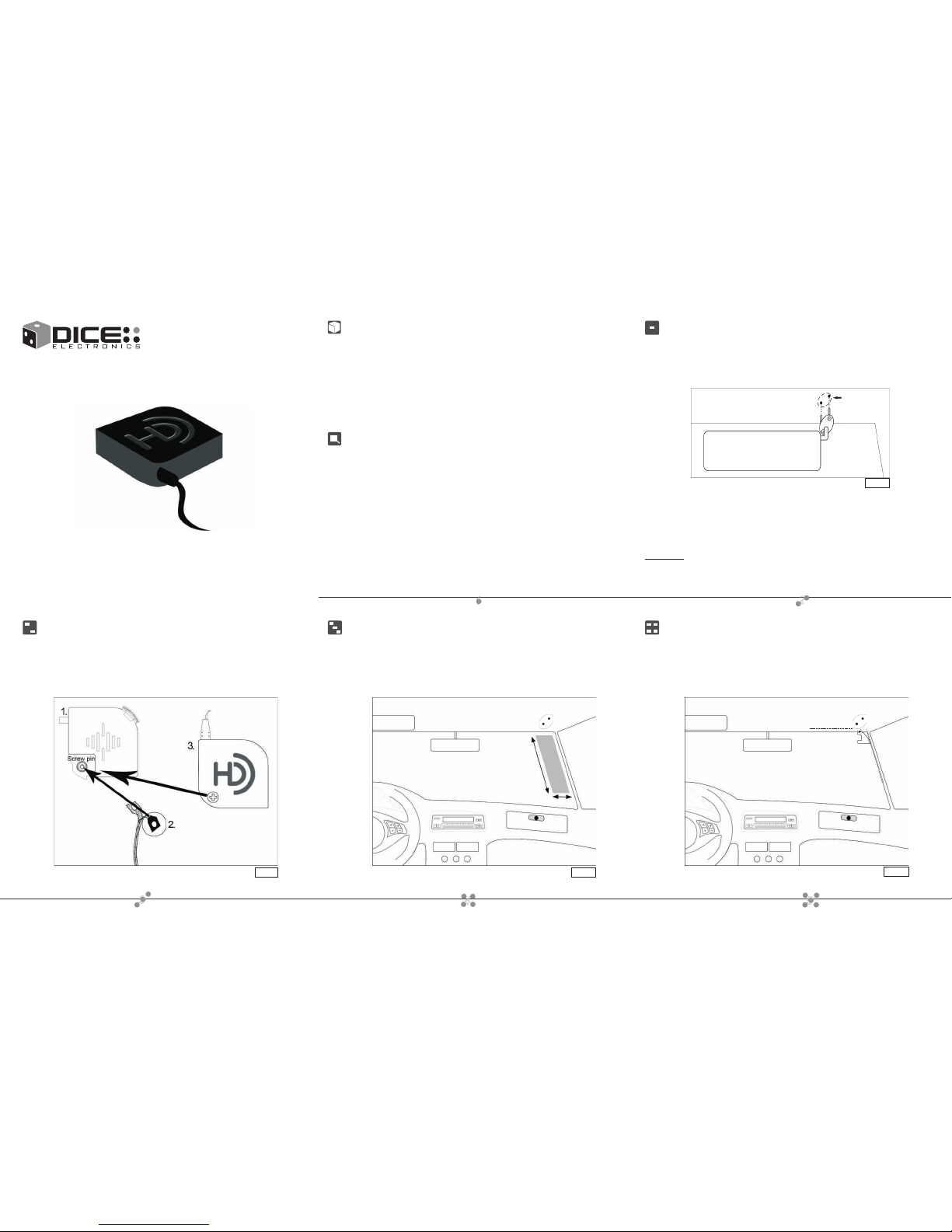
Cleaning of installation area.
Do not remove adhesive pad!
Strip back the protective film.
Hook the metal ring to the
screw pin on the mounting base.
Assembling of reception element and antenna
STEP 2: Take the mounting base and hook the ring found on the end of the reception
element to the screw pin located on the mounting base, adhesive side down. Place the
antenna module on the lower pin of the mounting base, then snap the module on to the
base. Fasten the module to the base by tightening the pre-mounted screw. Do not use a
powered screwdriver to avoid stripping the thread!
Vertical installation of the HD Radio Antenna
Figure 3 Figure 4
Figure 2Figure 2
NOTE: Horizontal installation of the antenna is also possible. (See figure 8 and 9.)
A-pillar
687
910 11
STEP 8: Unroll the antenna cable and push it under the headliner and A-pillar around
the front window and lead it down toward the dashboard (see figure no. 7). Route the
antenna cable towards mounting location of HD Radio receiver.
STEP 6:
STEP 7:
NOTE:
STEP 7.1:
STEP 7.2:
STEP 7.3:
NOTE:
STEP 7.4:
Remove the installation template.
Peel off the protective foil from the reception element by about 2 inches / 50 mm at a
time.
After peeling away protective foil approximately 1 inch / 25 mm from the pin, stick
this portion to the glass.
Stretch the reception element down parallel to the a-pillar (see figure no.6). Peel
the protective foil back from top to bottom. Hold the reception element in position with one
hand and use your other hand to press softly the reception element to the glass starting from
the mounting base making sure there are no kinks.
Continue applying the reception element all the way down to the end by peeling
the protective foil off and aligning the reception element adhesive backing.
Gently press the reception element against the front window.
Please note, if your front window is less than 600 mm in height, the reception element will
need to be shortened. The element should be kept about 1inch/25 mm away from the bottom of the
windshield.
The reception element should not be placed horizontally under the factory tinted window area
because in general such may contain reflective metal to keep the radiation out that interferes with
reception.
the A-Pillar cover to allow the headliner to move.
Reinstall the sun visor with the ground strap touching the exposed metal and hold the
ground strap in place with the visor mounting screw. Preferably the visor mounting
screw goes through the braided ground strap. Ensure that the sun visor is properly
installed.
STEP 9: Slide the ground strap under the headliner to the mounting base of the visor.
It may be necessary to uninstall
re-
Mounting the HD Radio Antenna
STEP 5 .- Peel off protective adhesive backing from mounting base Position the antenna
into the installation template adhered to the window with the screw pin positioned to the
lower left side. Press the pre-assembled antenna module against the front window with
gentle force. Hold it to the window for about 30 seconds.
Illustration no. 5
Peel off
the cover of
the adhesive
pad
Horizontal installation of the HD Radio Antenna
Horizontal placement of the antenna is possible, however you may experience
decreased reception performance when compared to a vertical placement. Assemble
the antenna and i
.
f needed, use a commercial window cleaner to remove dirt and grease
from the inside of the windshield. Then use the alcohol wipe included in the package to
clean the installation area for the antenna and reception element
Mount the antenna on the windshield, stick the reception element to the glass parallel to
the headliner. P the antenna cable
making sure not to obstruct the airbag. Then route the cable
. Always keep the antenna element at least 1" away from the roof.
ush under the headliner and A-pillar around the front
window down toward the
dashboard
A-pillar
Reception element
parallel to A-pillar
Installation complete
TIP: Use an multimeter to verify that the braid makes the proper ground connection.
Suggested
antenna
cable
routing
A-pillar
A-pillarA-pillar
Enjoy HD Radio with HD DICE!
HD DICE - Sound travel to the future
This antenna was designed for the HD DICE HD Radio interface. The use
of this antenna with other devices is not supported.
Reception performance of this antenna may be effected by the
geographical topology, and the distance of radio broadcast stations.
This antenna is only warranted in conjunction with the HD DICE receiver.
No separate warranty, expressed or implied applies.
About the antenna
Specifications
Impedance: 75 ohm
Power: 10V DC (max)
WARNING
DAMAGE TO THE COAXIAL CABLE WHILE THE ANTENNA IS
POWERED FROM THE HD-DICE MAY CAUSE PERMANENT DAMAGE
TO BOTH THE ANTENNA AND THE RECEIVER UNIT !
+
+
Figure 5
Figure 6 Figure 7
Figure 8 Figure 9
Reception element
parallel to headliner
Suggested
antenna
cable
routing

This manual suits for next models

1

Popular Antenna manuals by other brands

Vivanco TVA 2040 operating instructions

Vivanco

Vivanco TVA 2040 operating instructions

One Forall SV-9450 instruction manual

One Forall

One Forall SV-9450 instruction manual

Panasonic CA-GA60N installation instructions

Panasonic

Panasonic CA-GA60N installation instructions

Mars MA-WA56-DP25N quick start guide

Mars

Mars MA-WA56-DP25N quick start guide

Tarheel Antennas 100A-HP instruction manual

Tarheel Antennas

Tarheel Antennas 100A-HP instruction manual

SVS Humax Flach-Antenne H39D Series user manual

SVS

SVS Humax Flach-Antenne H39D Series user manual

DH Wireless Solutions MAST Assembly guide

DH Wireless Solutions

DH Wireless Solutions MAST Assembly guide

KING QUEST VQ4200 Quick reference guide

KING

KING QUEST VQ4200 Quick reference guide

TP-Link TL-ANT2414A user guide

TP-Link

TP-Link TL-ANT2414A user guide

Cisco FM TUBE Installation and configuration manual

Cisco

Cisco FM TUBE Installation and configuration manual

Vivanco 29947 operating instructions

Vivanco

Vivanco 29947 operating instructions

RCA ANT1275E quick start guide

RCA

RCA ANT1275E quick start guide

H3C ANT-5010Y Yagi manual

H3C

H3C ANT-5010Y Yagi manual

Laird AP-ANT-40 Assembly and installation instructions

Laird

Laird AP-ANT-40 Assembly and installation instructions

ETS-Lindgren 3110B manual

ETS-Lindgren

ETS-Lindgren 3110B manual

A.H. Systems SAS-550-1B Operation manual

A.H. Systems

A.H. Systems SAS-550-1B Operation manual

Televes Ellipse quick start guide

Televes

Televes Ellipse quick start guide

Patriot Antenna 1.8M MVSAT Installation and assembly instructions

Patriot Antenna

Patriot Antenna 1.8M MVSAT Installation and assembly instructions

manuals.online logo
manuals.online logoBrands
  • About & Mission
  • Contact us
  • Privacy Policy
  • Terms and Conditions

Copyright 2025 Manuals.Online. All Rights Reserved.