Dickey-John seed manager User manual

INTRODUCTION ................................................................................................................. 1
A . SYSTEM OVERVIEW ............................................................................................................ 1
B. SWITCH OVERVIEW ............................................................................................................ 2
1. ON•OFF .................................................................................................................................................. 2
2. ALARM .................................................................................................................................................... 2
3. SETUP ..................................................................................................................................................... 2
4. MIN-AVG-MAX•SCAN ...................................................................................................................... 2
5. SELECT ROW ....................................................................................................................................... 2
6. SELECT, SET, and CLEAR ................................................................................................................. 2
7. START•STOP ....................................................................................................................................... 2
SETUP MODE ........................................................................................................................ 3
A . CUSTOMER SETUP CONFIGURATION ........................................................................ 3
1. Ground Speed Sensor Type ............................................................................................................... 4
2. Shaft Speed Sensor Type .................................................................................................................... 4
3. Hopper Level 1 Sensor Enable ......................................................................................................... 4
4. Hopper Level 2 Sensor Enable ......................................................................................................... 5
5. Pressure 1 Sensor Enable .................................................................................................................... 5
6. Pressure 2 Sensor Enable .................................................................................................................... 6
7. Population Filter Value ....................................................................................................................... 6
8. Population Scaling Factor .................................................................................................................. 6
9. Boot Version Numbers ......................................................................................................................... 7
10. Flash Version Numbers ........................................................................................................................ 8
B. SETUP CONSTANTS ............................................................................................................. 9
1. IMPlement Type Configuration ......................................................................................................... 10
2. ROW Status ............................................................................................................................................ 11
3. POPULATION HI LIMIT .................................................................................................................... 12
4. POPULATION LO LIMIT ................................................................................................................... 12
5. NUMber of ROWS ................................................................................................................................13
6. ROW WIDTH ........................................................................................................................................ 13
7. IMPlement WIDTH ............................................................................................................................... 14
8. Shaft Speed Constant ........................................................................................................................... 14
9. RPM HI LIMIT (Shaft Speed) ........................................................................................................... 15
10. RPM LO LIMIT (Shaft Speed)........................................................................................................... 15
11. Hi Pressure Warning Limit .................................................................................................................. 16
12. Lo Pressure Warning Limit ................................................................................................................. 16
13. Distance Calibration............................................................................................................................. 17
14. Sensor Self-Test ..................................................................................................................................... 18
15. English/METRIC Units Selection ...................................................................................................... 19
OPERATE MODE ................................................................................................................. 21
A . OPERATE MODE .................................................................................................................... 21
1. Run Hours .............................................................................................................................................. 21
2. Population............................................................................................................................................... 22
a. Population SCAN ................................................................................................................................22
b. Population MIN-AVG-MAX .............................................................................................................. 23
c. Population SELECT ROW ................................................................................................................ 23
3. Seed Spacing ......................................................................................................................................... 24
4. Singulation.............................................................................................................................................. 24
5. Speed ....................................................................................................................................................... 25
6. Shaft Speed ............................................................................................................................................ 25
7. Distance Accumulator.......................................................................................................................... 26
8. Area Accumulator 1 ............................................................................................................................ 26
9. Area Accumulator 2 ............................................................................................................................ 27
CONTENTS

10. Area Accumulator 3 ............................................................................................................................. 27
11. Seed Count ............................................................................................................................................. 28
B. SPEED-AREA MODE.............................................................................................................. 28
C . POPULATION BARGRAPH ................................................................................................. 29
D. BARGRAPH LOCK & HOLD ............................................................................................... 31
ALARMS & ERROR CODES ............................................................................................. 33
A. ALARMS..................................................................................................................................... 33
1. Distance Sensor FAILED .................................................................................................................... 33
2. ROW FAILED ........................................................................................................................................ 34
3. All ROWS FAILED .............................................................................................................................. 34
4. Lock-On ROW FAILED ...................................................................................................................... 35
5. POPULATION HI LIMIT Warning ................................................................................................... 35
6. POPULATION LO LIMIT Warning .................................................................................................. 36
7. RPM HI LIMIT (Shaft Speed) Warning .......................................................................................... 36
8. RPM LO LIMIT (Shaft Speed) Warning ......................................................................................... 36
9. HI PRESSURE Limit Warning ......................................................................................................... 36
10. LO PRESSURE Limit Warning ........................................................................................................ 36
11. HOPPER LO Warning ......................................................................................................................... 38
12. Battery Voltage Warning ..................................................................................................................... 38
B. ERROR CODES ........................................................................................................................ 39
SYSTEM INSTALLATION ................................................................................................. 41
A . CONSOLE MOUNTING ........................................................................................................ 41
B. CONSOLE HARNESSES INSTALLATION .................................................................... 42
C . GROUND SPEED SENSOR INSTALLATION ............................................................... 44
D. OTHER SENSORS .................................................................................................................. 45
E. POWER CONNECTION ........................................................................................................ 46
F. SEED SENSORS ....................................................................................................................... 47
G. PLANTER HARNESS ............................................................................................................. 48
1. STANDARD and HI-RATE HARNESSES INSTALLATION ..................................................... 48
2. SQUADRON HARNESS INSTALLATION ..................................................................................... 49
3. SEED SMART® HARNESS INSTALLATION .............................................................................. 50
TROUBLESHOOTING ........................................................................................................ 51
A. MONITOR DEAD .................................................................................................................................... 51
B. BATTERY SYMBOL APPEARS ON DISPLAY .............................................................................. 51
C. ERROR CODE E 020 ............................................................................................................................. 51
D. ERROR CODE E 021 ............................................................................................................................. 51
E. ERROR CODE E 060 ............................................................................................................................. 52
F. ERROR CODE E 062 ............................................................................................................................. 52
G. ERROR CODE E 063 ............................................................................................................................. 52
H. ERROR CODE E 064 ............................................................................................................................. 52
I. ERROR CODE E 065 ............................................................................................................................. 53
J. ERROR CODE E 066 ............................................................................................................................. 53
K. ERROR CODE E 067 ............................................................................................................................. 53
L. ERROR CODE E 080 ............................................................................................................................. 53
M. ERROR CODE E 081 ............................................................................................................................. 54
N. ERROR CODE E 082 ............................................................................................................................. 54
O. ERROR CODE HOPPER FAILURE ................................................................................................... 54
P. ERROR CODE PRESSURE FAILURE ............................................................................................... 54
SETUP RECORD SHEET .................................................................................................... 55

BENCHMARK Series®
OPERATOR'S MANUAL
Dj SEED MANAGER ® PLANTER MONITOR INTRODUCTION/ 1
11001-1103A-200111
A. SYSTEM OVERVIEW
The DICKEY-john Seed Manager®
Population Monitor uses the latest
microprocessor-based technology to
take the guesswork out of the planting
operation. Any time seeds are not going
to the ground at the correct rate or
another error condition occurs, an
alarm is sounded and a message and
row number, if appropriate, are dis-
played.
Seed Manager®offers features such as
improved seed counting accuracy, simpli-
fied harnessing, advanced error diagnos-
tics, and seed singulation when used with
the new Seed Smart®sensors. It is also
compatible with the DICKEY-john
Standard and Hi-Rate seed sensors.
Additional features include a bargraph
presentation of row-to-row planter
performance, high and low population
warnings, faster population updates, and
the ability to disable individual row
sensors from the monitor. An RS-232
interface is available for precision farming
applications.
The Seed Manager®Population Monitor can
monitor up to 36 rows. It stores planter
configuration data and accumulated opera-
tional data in nonvolatile memory, retaining
information even when disconnected from
the tractor battery.
Figure 1 shows the Seed Manager®Popula-
tion Monitor console. It consists of two
custom Liquid Crystal Displays (LCDs) and
twelve membrane switches. The top LCD
display shows messages for the selected
Figure 1
Seed Manager®Console
INTRODUCTION
®

2/ INTRODUCTION
BENCHMARK Series®
OPERATOR'S MANUAL
Dj SEED MANAGER ® PLANTER MONITOR
11001-1103A-200111
Operate Mode function, Setup Mode
constant, or Alarm Mode identifier and the
value on a 5-digit numeric display. A 2-Digit
numeric display identifies the row. The
bottom LCD displays graphically the relative
populations of 12 rows simultaneously.
Larger planters have row groups dis-
played on a time-shared basis.
B. SWITCH OVERVIEW
The switches are used to control system
power, select the mode of operation, and
enter planter configuration constants. To
help distinguish between switch names
and display messages in the text of this
manual, switch names are always shown
in italicized print. An overview of the
switches follows:
1. ON•OFF
Pressing this switch applies power to the
monitor. Upon power up, the monitor
performs internal diagnostic checks,
illuminates all segments of the LCDs,
sounds the alarm, and determines what
type of seed sensor harness is connected.
Depressing the ON•OFF switch for at
least one second causes the monitor to
power down.
2. ALARM
Momentarily pressing this switch silences
the alarm and acknowledges the alarm
condition. Additionally, holding the
switch pressed for more than one second
allows the volume level of the alarm to be
adjusted. As the switch is held pressed,
the alarm sounds continuously and the
volume level slowly decreases to a minimum,
then increases to a maximum. Releasing the
switch establishes the desired volume level.
3. SETUP
This switch is pressed for one (1) second
to enter the Setup Mode and to step from
one Setup constant to the next as detailed
in the SETUP chapter.
4. MIN-AVG-MAX•SCAN
This switch is pressed to toggle between
the MIN-AVG-MAX and SCAN options
for the function selected by the Popula-
tion• Spacing•Singulation switch.
5. SELECT ROW
Pressing this switch while in the Popula-
tion, Spacing, or Singulation functions
freezes the upper LCD display on the
current row data. Successive depressions
then cause stepping from one row to the
next. In the Setup Mode, this switch
allows stepping through the rows while
entering Row Status.
6. SELECT, SET, and CLEAR
These switches are used to change constants
in the Setup Mode as explained in the
SETUP chapter. The CLEAR switch is also
used in the Operate Mode to reset the area
and distance accumulators and the Run
Hours function. The SELECT switch is used
in the Operate Mode to select various
Bargraph Display/Sections.
7. START•STOP
This switch is used in the Operate Mode
Seed Count, Distance Accumulator, and
Bargraph Lock & Hold functions. In the
Setup Mode, it is used for the Distance
Calibration and the Sensor Self-Test.

BENCHMARK Series®
OPERATOR'S MANUAL
Dj SEED MANAGER® PLANTER MONITOR SETUP MODE/ 3
11001-1103A-200111
SETUP MODE
A. CUSTOMER SETUP
CONFIGURATION
Certain parameters must be entered in the
Setup Configuration to the console. This
mode is used to specify the types of ground
speed and shaft speed sensors used, enable
or disable hopper level sensors, to enable or
disable pressure sensors, set population filter
and scaling factor and identify the software
version.
The Setup Configuration is entered by
holding the Setup switch depressed while
powering on the console and continuing to
hold it depressed until the Display Test
begins. A flashing SETUP message indicates
the console is in the Setup Configuration
Mode.
Additional messages uniquely identify the
parameter displayed and available for editing.
Use the SELECT, SET, and CLEAR
switches as described previously to enter or
change parameters. Also, press Setup, as
before, to store the value and advance to the
next parameter. To exit the Customer Setup
Mode, power off the console.
Figure 2 shows the Customer Setup parame-
ters, in the order of their presentation. As
before, record all parameter values on the
SETUP RECORD sheet on the last page of
this manual, immediately after console entry.
Definitions and considerations when entering
values for each parameter are as follows:
Figure 2
Customer Setup Parameter Chart
1 Ground Speed Sensor Type
2 Shaft Speed Sensor Type
3 Hopper Level 1 Sensor Enable
4 Hopper Level 2 Sensor Enable
5* Hopper Pressure 1 Sensor Enable
6* Hopper Pressure 2 Sensor Enable
7* Population Filter Value
8* Population Scaling Factor
9 Boot Version Number
10 Flash Version Number
* New For Version 5.0 Software
4/ SETUP MODE
BENCHMARK Series®
OPERATOR'S MANUAL
Dj SEED MANAGER® PLANTER MONITOR
11001-1103A-200111
1. Ground Speed Sensor Type
This parameter allows choosing between a
digital (radar or Hall Effect) type or reluc-
tance type ground speed sensor. This
parameter is identified by the message
SPEED and a flashing SETUP message.
Pressing the SET switch causes the lower,
right display to toggle between a flashing
"d1" or "r1". If a digital (radar or Hall
Effect) type ground speed sensor is used,
press the SET switch until "d1" appears. If
a reluctance type ground speed sensor is
used, press the SET switch until "r1"
appears. Figure 3 shows a digital type ground
speed sensor selected.
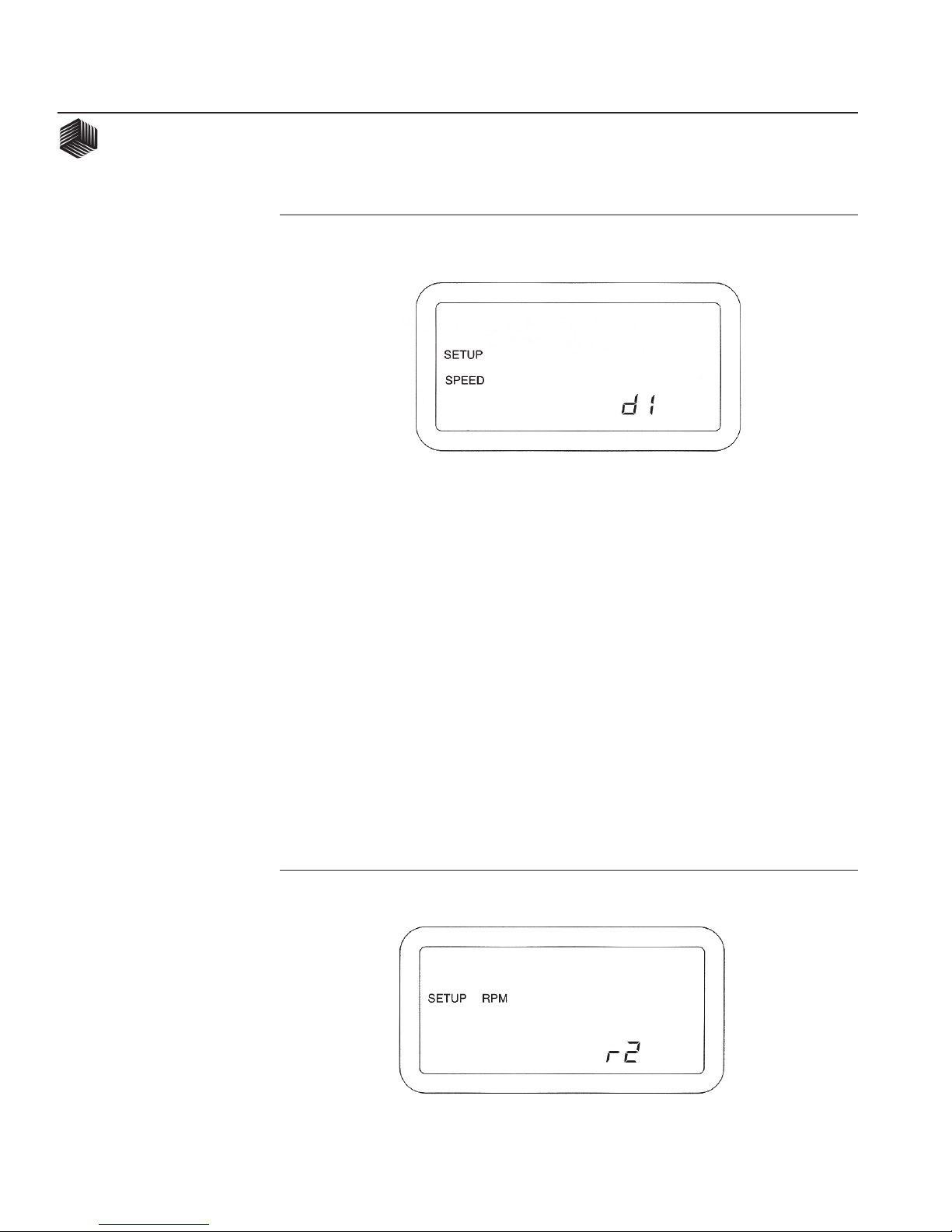
2. Shaft Speed Sensor Type
This parameter allows choosing between a
digital 1, digital 2, reluctance 1, or reluctance
2 type shaft speed sensor. This parameter is
identified by the message RPM and a flashing
SETUP message. Pressing the SET switch
causes stepping between "d1, d2, r1, and r2"
flashing on the lower, right display. The shaft
speed sensor type used is clearly labeled on
the sensor cable. Figure 4 shows a reluctance
2 type shaft speed sensor selected.
3. Hopper Level 1 Sensor Enable
This parameter enables or disables the
DICKEY-john Hopper Level 1 Sensor. It
is identified by the message HOPPER, a "1"
Figure 3
Ground Speed Sensor Type Display
Figure 4
Shaft Speed Sensor Type Display

BENCHMARK Series®
OPERATOR'S MANUAL
Dj SEED MANAGER® PLANTER MONITOR SETUP MODE/ 5
11001-1103A-200111
on the lower, right display, a flashing SETUP
message, and either the ON or OFF message
flashing. To enable or disable, press the SET
switch to select ON or OFF respectively.
Figure 5 shows the hopper level sensor is
enabled.
4. Hopper Level 2 Sensor Enable
This parameter enables or disables the
DICKEY-john Hopper Level 2 Sensor. It
is identified by the message HOPPER, a
"2" on the lower, right display, a flashing
SETUP message, and either the ON or
OFF message flashing. To enable or
disable, press the SET switch to select ON
or OFF respectively.
Figure 5
Hopper Level Sensor Display
5. Pressure 1 Sensor Enable
This parameter enables or disables the
hopper pressure sensor #1. This is identified
on the display by the message “PRESS”, “1”,
and the flashing SETUP icon. To enable
disable, press the SET switch to select ON or
OFF respectively. Figure 6 below shows
PRESSURE 1 enabled.
Figure 6
Pressure I Enable

6/ SETUP MODE
BENCHMARK Series®
OPERATOR'S MANUAL
Dj SEED MANAGER® PLANTER MONITOR
11001-1103A-200111
6. Pressure 2 Sensor Enable
This parameter enables or disables the
hopper pressure sensor #2. This is identified
on the display by the message “PRESS”, “2”,
and the flashing SETUP icon. To enable/
disable, press the SET switch to select ON or
OFF respectively. Figure 7 shows PRES-
SURE 2 disabled.
7. Population Filter Value
In certain applications the Seed Manager®,
due to its rapid update rate, might exhibit
fluctuations in population, spacing, and
singulation that are undesirable to the
operator. The population filtering option
applies an averaging filter to the population,
and seed spacing calculations. The filter
values range from 0 to 99, with 0 having no
filtering effect and 99 being the maximum
filtering value. Use the SET and SELECT
switches to adjust the filtering value. Figure 8
shows a light filter value of 15.
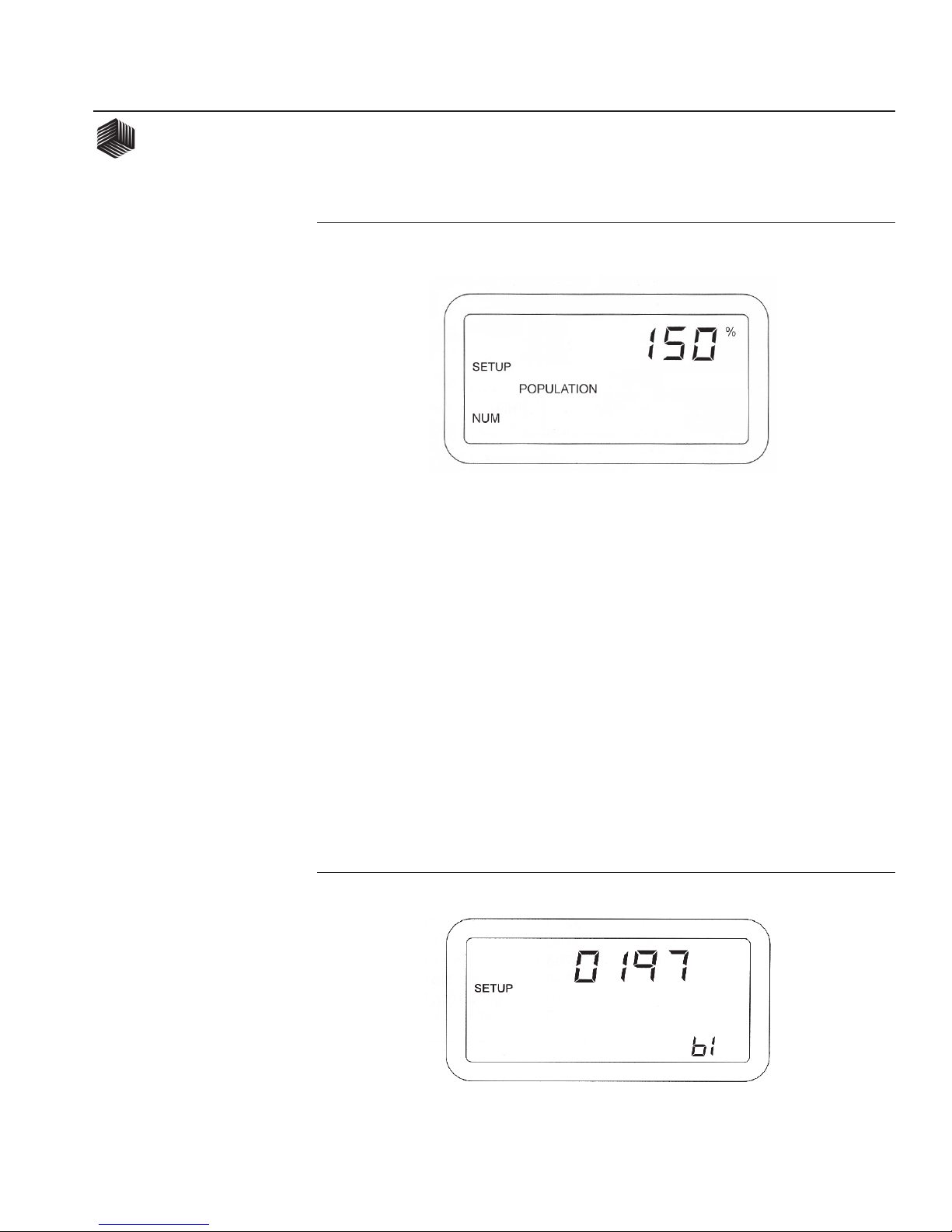
8. Population Scaling Factor
The population scaling factor allows the
operator to make fine adjustments in the
readout of population and spacing on a
Figure 7
Pressure 2 Disable
Figure 8
Filter Value
BENCHMARK Series®
OPERATOR'S MANUAL
Dj SEED MANAGER® PLANTER MONITOR SETUP MODE/ 7
11001-1103A-200111
Figure 10
Boot Number
percentage basis. This value is adjustable
from 1% to 999% with the factory value being
100%. Use the SET and SELECT switches
to adjust to the desired population scaling
factor. Figure 9 shows a population scaling
factor of 150%. Increasing this value results
in an increase of population readout, while
decreasing this value results in a decrease of
the readout..
Examples:
To increase the population display 15%,
enter 115%.
To decrease the population display 13%,
enter 87%.
9. Boot Version Numbers
DICKEY-john's Service department may
request the customer to observe, record, and
report back the four different 4-digit num-
bers (to identify the "boot memory" software
version) in the unlikely event field problems
occur.
The first 4-digit number shows on the upper
numeric display at the same time a "b1"
identifier appears on the lower numeric
Figure 9
Population Scaling Factor
8/ SETUP MODE
BENCHMARK Series®
OPERATOR'S MANUAL
Dj SEED MANAGER® PLANTER MONITOR
11001-1103A-200111
display. Record this number, then press and
release the SELECT switch to step to the
"b2", "b3", and "bc" numbers, recording each
4-digit number along with its identifier. (To
return to "b1", press SELECT again.) Press
the SETUP switch to advance to the next
constant. Figure 10 shows "0197" for "b1", the
first Boot Version Number.
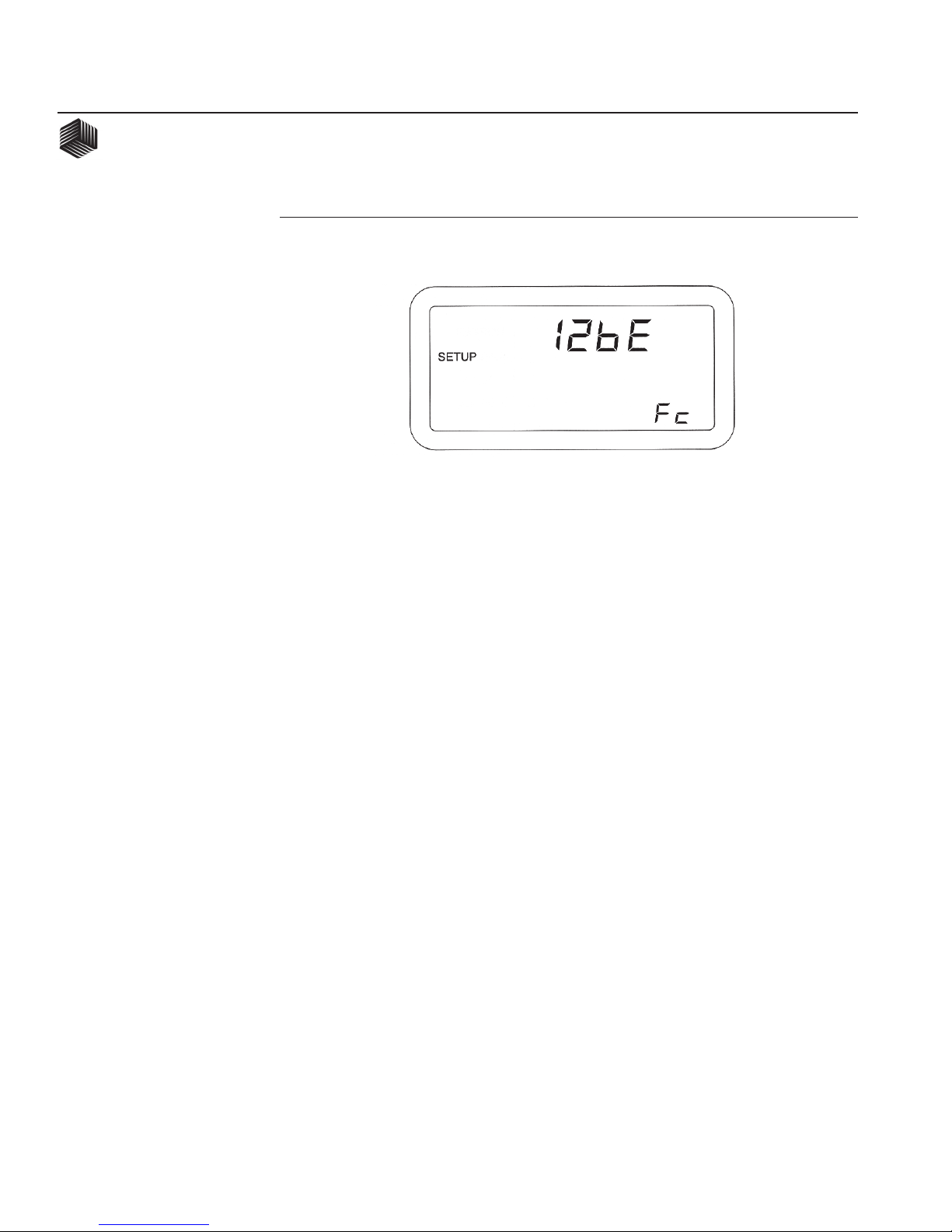
10. Flash Version Numbers
DICKEY-john's Service department may
request the customer to observe, record, and
report back the four different 4-digit num-
bers (to identify the "flash memory" software
version) in the unlikely event field problems
occur.
The first 4-digit number shows on the upper
numeric display at the same time a "F1"
Figure 11
Flash Version Number
identifier appears on the lower numeric
display. Record this number, then press and
release the SELECT switch to step to the
"F2", "F3", and "Fc" numbers, recording each
4-digit number along with its identifier. (To
return to "F1", press SELECT again.) Figure
11 shows "12bE" for "Fc", the last Flash
Version Number.
Pressing the SETUP switch again causes a
return to the first Customer Setup param-
eter, Ground Speed Sensor Type. To exit
the Customer Setup Mode, power off the
console.

BENCHMARK Series®
OPERATOR'S MANUAL
Dj SEED MANAGER® PLANTER MONITOR SETUP MODE/ 9
11001-1103A-200111
B. SETUP CONSTANTS
The Setup Mode is used to enter the planter
configuration constants which are listed in
Figure 12, in the order of their presentation.
Depressing the Setup switch for one (1)
second places the console in the Setup
Mode, which is identified by the SETUP
message on the display. Additional messages
uniquely identify the constant displayed and
available for editing at any given time.
Each constant has a fixed number of digits.
Leading zeroes are displayed. When it is
desired to change the value of a constant, use
the SELECT, SET, and CLEAR switches as
follows:
Initially, the left most digit flashes on and
off, indicating it is the “selected digit”.
Each depression of the SET switch
increases the selected digit by one count.
After reaching the maximum value of
nine (9), the digit rolls over to zero (0).
Pressing CLEAR zeroes the digit. Each
depression of the SELECT switch makes
the next digit to the right the selected
digit.
When the desired value is entered (or
there is no change from the original
value), press the Setup switch to store
the value and advance to the next
constant on the list. If a value is
entered which exceeds the minimum
or maximum shown for that constant
Figure 12
Setup Mode Parameters
Order SETUP Mode Default Miniuum Maximum
CONSTANT Name
1. IMPlement Type Config. 01 01 N/A
2. Row Status ON N/A N/A
3. POPULATION HI LIMIT 0034.0 0000.0 9999.9
4. POPULATION LO LIMIT 0026.0 0000.0 9999.9
5. NUMber of ROWS N/A 1 36
6. ROW WIDTH 030.0 001.0 999.9
7. IMPlement WIDTH N/A 0001.0 9999.9
8. Shaft Speed Constant 000.00 000.00 999.99
9. RPM HI LIMIT 0065 0000 9999
10. RPM LO LIMIT 0045 0000 9999
11.* Hi Pressure 000.0 000.0 999.9
12.* Lo Pressure 000.0 000.0 999.9
13. Distance Calibration 6096 250 9999
14. Sensor Self-Test N/A N/A N/A
15. English/METRIC Units English N/A N/A
* IF PRESSURE SENSORS HAVE NOT BEEN ENABLED, THESE CONSTANTS ARE SKIPPED

10/ SETUP MODE
BENCHMARK Series®
OPERATOR'S MANUAL
Dj SEED MANAGER® PLANTER MONITOR
11001-1103A-200111
in Figure 12, the alarm sounds for one (1)
second, the value of the exceeded limit
appears on the screen, and the advance to
the next constant is aborted.
CAUTION: To allow rapid recovery from
an entry error, it is important to record all
values of constants on the SETUP
RECORD sheet on the last page of this
manual, immediately after console entry.
To exit the Setup Mode, press any of the
three Operate Mode switches (Population
•Spacing•Singulation, Area• Seed Count,
or Speed•Shaft Speed•Dist Acc). Exiting
automatically stores the last constant
changed.
The first parameter displayed after entering
the Setup Mode is Implement type Configura-
tion. Definitions and considerations when
entering values for each constant are as follows:
Figure 13
IMPlement Type Configuration Display
1. IMPlement Type Configuration
Find the number identifying the specific
planter type on the "Planter Configuration
Instruction" (DICKEY-john Document No.
11001-1107). Enter this number using the
SELECT and SET switches. The SETUP
and IMP messages identify the display. This
parameter defines the number of rows, the
row number for each sensor, and the
bargraph display arrangement. Figure 13
shows IMPlement Type Configuration 17
selected.
BENCHMARK Series®
OPERATOR'S MANUAL
Dj SEED MANAGER® PLANTER MONITOR SETUP MODE/ 11
11001-1103A-200111
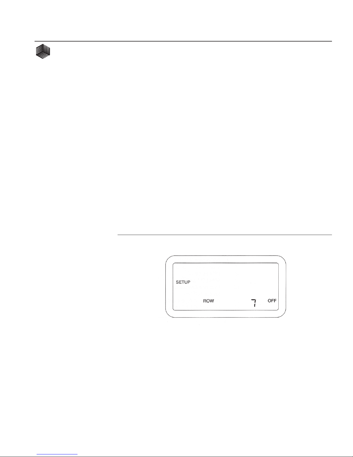
2. ROW Status
This parameter allows placing individual seed
sensors in ON, OFF, or SKIP status. For
those situations where it is necessary to turn
off certain rows on the planter (for example,
with skip row planters or when planting point
rows or seed corn), OFF status turns off the
related sensors so alarms do not occur. The
SKIP status setting, available only with Seed
Smart®sensors, allows removing a failed
sensor from the harness “daisy-chain” (and
jumpering with an extension harness) without
disrupting row numbering.
Figure 14
Row Status Display
The display initially shows the messages
SETUP, ROW, 1, and the status of
row 1. Figure 14 shows row 7 status set to
OFF. Press the SET switch to toggle between
ON and OFF for the Standard and Hi-Rate
seed sensors and between ON, OFF, and
SKIP for the Seed Smart®sensor. Press the
SELECT ROW switch to advance to the
next row. When the status of all rows is
correctly entered, press Setup to advance to
the next Setup constant.
12/ SETUP MODE
BENCHMARK Series®
OPERATOR'S MANUAL
Dj SEED MANAGER® PLANTER MONITOR
11001-1103A-200111
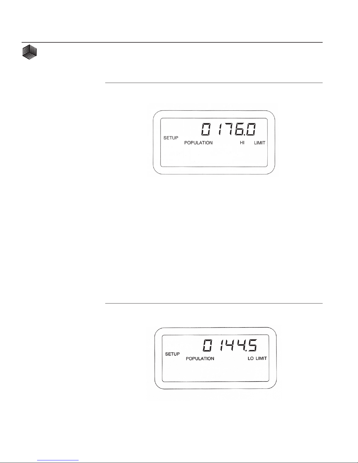
3. POPULATION HI LIMIT
When the population on any row exceeds
the value entered for this constant, in
thousands of seeds per acre (hectare), the
alarm sounds, as indicated under the
heading ALARMS, POPULATION HI
LIMIT Warning. Figure 15 shows the display
for a limit of 176,000 seeds/acre.
4. POPULATION LO LIMIT
When the population on any row falls below
the value entered for this constant, in
thousands of seeds per acre (hectare), the
alarm sounds, as indicated under the heading
ALARMS, POPULATION LO LIMIT
Warning. Figure 16 shows the display for a
limit of 144,500 seeds/acre.
Figure 15
POPULATION HI LIMIT Display
Figure 16
POPULATION LO LIMIT Display

BENCHMARK Series®
OPERATOR'S MANUAL
Dj SEED MANAGER® PLANTER MONITOR SETUP MODE/ 13
11001-1103A-200111
5. NUMber of ROWS
This parameter is used to calculate IMPle-
ment WIDTH and is used in checking the
number of sensors detected upon system
power up. This value is displayed for
confirmation and can only be altered by
changing the IMPlement Type Configuration
parameter. Figure 17 shows the display for
sixteen (16) rows.
6. ROW WIDTH
This is the distance in inches (centimeters)
between furrows, with a resolution of 0.1.
Figure 18 shows a ROW WIDTH of 38.0
inches.
Figure 17
NUMber of ROWS Display
Figure 18
ROW WIDTH Display
14/ SETUP MODE
BENCHMARK Series®
OPERATOR'S MANUAL
Dj SEED MANAGER® PLANTER MONITOR
11001-1103A-200111
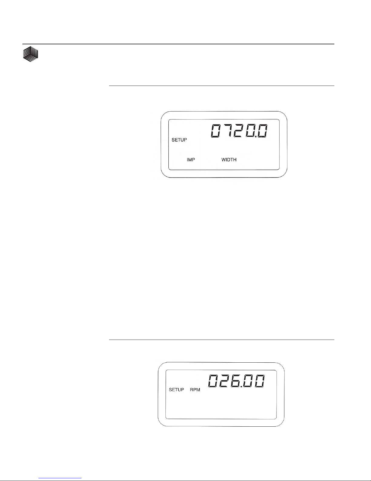
7. IMPlement WIDTH
This is the planting width of the planter in
inches (centimeters) with a resolution of
0.1. It is automatically calculated when
either the NUMber of ROWS or the
ROW WIDTH is changed and can be
edited for special applications such as skip
row planters. Figure 18 shows an IMPlement
WIDTH of 720 inches.
8. Shaft Speed Constant
The Shaft Speed Constant is the number of
pulses the shaft speed sensor generates in
one revolution of the monitored shaft. This is
typically the number of teeth (sense points)
on the gear attached to the monitored shaft.
If the sense gear is not directly attached to
the monitored shaft, the Shaft Speed
Constant can be entered as a decimal with
0.01 resolution. Entering a value of zero
(000.00) disables the Shaft Speed function.
Figure 19 shows the display with the SETUP
and RPM messages and a Shaft Speed
Constant of 26 pulses per revolution.
Figure 18
IMPlement WIDTH Display
Figure 19
Shaft Speed Constant Display

BENCHMARK Series®
OPERATOR'S MANUAL
Dj SEED MANAGER® PLANTER MONITOR SETUP MODE/ 15
11001-1103A-200111
9. RPM HI LIMIT (Shaft Speed)
This constant is the highest shaft RPM
allowed before sounding a warning alarm.
The warning is enabled or disabled by
selecting the ON or OFF message. Use the
SELECT switch to advance one step to the
right of the right most digit, then press the
SET switch to toggle between ON and OFF.
Figure 20 shows a limit of 65 RPM with the
warning enabled.
10. RPM LO LIMIT (Shaft Speed)
This constant is the lowest shaft RPM
allowed before sounding a warning alarm.
The warning is enabled or disabled by
selecting the ON or OFF message. Use the
SELECT switch to advance one step to the
right of the right most digit, then press the
SET switch to toggle between ON and OFF.
Figure 21 shows a limit of 12 RPM with the
warning disabled.
Figure 20
RPM HI LIMIT Display
Figure 21
RPM LO LIMIT Display

16/ SETUP MODE
BENCHMARK Series®
OPERATOR'S MANUAL
Dj SEED MANAGER® PLANTER MONITOR
11001-1103A-200111
Figure 22
Hi Pressure Limit
Figure 23
Lo Pressure Limit
11. Hi Pressure Warning Limit
The Hi Pressure Warning Limit is entered in
oz/in2 (kPa) and applies to both PRESSURE
sensors if used. The Hi and Lo warning
limits are accessible only if PRESSURE 1
and/or PRESSURE 2 sensors have been
enabled in the customer setup mode. Setting
the Hi Pressure Warning Limit will cause the
audible alarm to sound when the pressure
exceeds the value that has been entered.
Utilize the SELECT and SET switch to enter
the Hi Pressure Warning Limit. The Hi
Pressure Warning Limit can be enabled or
disabled by selecting the ON or OFF symbol
after the rightmost digit. Pressing the SET
switch will toggle the status of the warning
from ON to OFF. Figure 22 shows a Hi
Pressure Warning Limit of 15 oz/in2 with the
alarm turned ON.
12. Lo Pressure Warning Limit
The Lo Pressure Warning Limit is entered in
oz/in2 (kPa) and applies to both PRESSURE
sensors if used. The Lo and Hi warning
limits are accessible only if PRESSURE 1
and/or PRESSURE 2 sensors have been
enabled in the customer setup mode. Setting
the Lo Pressure Warning Limit will cause the
audible alarm to sound when the pressure

BENCHMARK Series®
OPERATOR'S MANUAL
Dj SEED MANAGER® PLANTER MONITOR SETUP MODE/ 17
11001-1103A-200111
falls below the value that has been entered.
Utilize the SELECT and SET switch to enter
the Lo Pressure Warning Limit. The Lo
Pressure Warning Limit can be enabled or
disabled by selecting the ON or OFF symbol
after the rightmost digit. Pressing the SET
switch will toggle the status of the warning
from ON to OFF. Figure 23 shows a Lo
Pressure Warning Limit of 5 oz/in2 with the
alarm turned OFF.
13. Distance Calibration
The Distance Calibration Constant is the
number of pulses generated by the
ground speed sensor while traveling a
distance of 400 feet (122 meters). Figure 24
shows the display with the SETUP, SPEED,
and COUNT messages and the default value
of 6096, which is the nominal pulse count for
the radar ground speed sensor. A smaller
number, typically 3100, results with a
reluctance ground speed sensor.
To perform the Distance Calibration:
Step 1.
Carefully measure a 400 foot (122 meter)
course, plainly marking the start and finish
points.
Step 2.
With the tractor moving between 2 and 5
MPH (3.2 and 8Km/h), press the
START•STOP switch when the tractor
is exactly even with the start marker. The
display showing the Distance Calibration
Constant zeroes, then counts the ground
speed pulses.
Step 3.
When even with the finish marker,
press the START•STOP switch.
Step 4.
To ensure best accuracy, perform this
procedure at least three times. Record the
count each time, then enter the average as
the Distance Calibration Constant, using
the SELECT and SET switches.
Figure 24
Distance Calibration Display

18/ SETUP MODE
BENCHMARK Series®
OPERATOR'S MANUAL
Dj SEED MANAGER® PLANTER MONITOR
11001-1103A-200111
14. Sensor Self-Test
This test functions differently depending
upon the type of seed sensors used on the
planter. It is identified on the display by
the SETUP, TEST, and ROW messages.
Start the test by pressing the START•
STOP switch. The TEST message flashes
while the test is executing and PASSED
appears when complete. (This same test is
performed automatically during console
power up.)
If one or more sensors fail, the message
FAILED and the row number of the first
failed sensor is displayed. When multiple
sensors fail, the "S" appears after the
ROW message (displaying the message
ROWS) and the SELECT ROW switch can
be pressed to step through the failed row
numbers. Figure 25 shows the display when
multiple rows have failed.
If Standard or Hi-Rate sensors are used, each
sensor is tested in sequence. The number of
sensors passing is then compared with the
NUMber of ROWS and IMPlement Type
Configuration parameters to ensure agree-
ment.
For Seed Smart® sensors, the light path,
circuitry, and communication link of each
sensor is tested by an instruction which
simulates dropping seeds, resulting in
more comprehensive diagnostic informa-
tion. Figure 26 shows the error codes
possible (See ALARMS & ERROR CODES
Figure 25
Sensor Self-Test Display
Figure 26
Seed Smart® Sensor Error Codes
Other manuals for seed manager
1
Table of contents


