Dickson Industrial SM720 User manual
Rev. 01/09
DICKSON
SM720/SM725 & TM725
Midsize Display Loggers Operation
Contents:
Product Applications and Useful Features
Product Specifications
Operating Instructions / Getting Started
Network Setup
DicksonWare Software Specifications
Product Accessories
Frequently Asked Questions
Calibrations
Troubleshooting
Warranty / Factory Service & Returns
Product
Applications &
Specifications
DICKSON
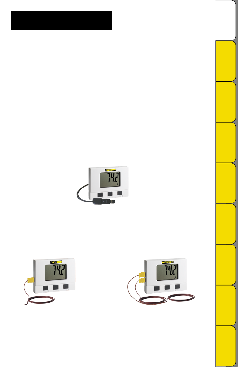
TM725
Remote Probe Temperature
& Humidity Logger
SM720
2 Channel Temperature Logger
(Internal & Remote K-TC)
SM725
2 K-TC Channel Temperature
Data Logger
Instructions /
Getting Started/
Network Setup
DicksonWare
Software
Specifications
Accessories/
Calibrations/
Troubleshooting
Spanish French German Italian

Rev. 01/09
Product
Applications &
Specifications
Product Applications
Dickson’s series of Temperature / Temperature and Humidity Data Loggers with Jumbo Display offer all of the
key features you’ve been looking for including: Ethernet Connectivity, High/Low Alarm, Min/Max Display,
Super high-speed USB 2.0 Connectivity, and much more! Our High Accuracy TM725 model offer ±0.8°F
temperature accuracy. All of these features combined with Dickson quality and accuracy will make this your
most valuable temperature and humidity monitoring tool.
Featuring our fastest data download ever! Download data in just seconds, using new
USB port compared to 1.5 minutes using standard serial port.
TM725
Monitoring HVAC/R Systems
Recording Conditions in Clean Rooms
Monitoring Walk in Freezers and Refrigerators
Monitoring Incubators and Chambers
Remote probe is perfect for hard to reach locations!
SM720 & SM725
Monitoring HVAC/R Systems
Evaluating Conditions in Freezers and Ovens
Monitoring Temperatures in Autoclaves, Baths and Incubators
Monitoring Conditions in Clean Rooms
Remote probe is perfect for hard to reach locations and extreme temperatures!*
*Using optional A203 remote K-Thermocouple probe
Useful Features
Ethernet Connectivity
±0.8°F Temperature Accuracy (TM725)
Available: Extreme temperature range (-300 to +2000°F) models SM720 & SM725
Temperature and humidity remote probe model TM725
Huge digital display (0.9” numerals) with minimum and maximum displayed at the touch of a button
Optional AC adapter
Stores 32,000 sample points
Product Specifications
SM720 SM725 TM725
Internal Temp. Accuracy: ±1.8°F (±1°C) ±1.8°F (±1°C)
External Temp. Sensor: Thermocouple (2) Thermocouple Thermistor
External Temp. Range: -300 to +2000˚F (-184
to +1093˚C)
-300 to +2000˚F
(-184 to +1093˚C) -40 to +185°F
(-40 to +85°C)
External Temp. Accuracy: ±1.8°F (±1°C) (unit) ±1.8°F (±1°C) (unit) ±0.8°F (±0.5°C)
R/H Sensor Type: Monolithic IC Humidity
Sensor
% R/H Accuracy: ±2% RH @ 77°F
(25°C), 0 to 95%
•
•
•
•
•
•
•
•
•
•
•
•
•
•
•
•
•
Instructions /
Getting Started/
Network Setup
DicksonWare
Software
Specifications
Accessories/
Calibrations/
Troubleshooting
Spanish French German
DICKSON
Italian

Rev. 01/09
Product
Applications &
Specifications
DICKSON
Getting Started
Install the DicksonWare™ Software.
Connect the cable (supplied with the software) to the logger and to a working serial or USB port on
your computer.
Click the Setup button. When the setup window appears, all fields should be automatically filled
in, this will confirm that DicksonWare has recognized the logger. Should all fields remain blank, refer to
“No Communication” in the Trouble Shooting section of this manual. Once DicksonWare™ recognizes
the logger, press the Clear button. This will delete all data currently stored.
The logger is now sampling and ready for use, a Delta (∆) symbol will appear in the display to confirm
logging. The default sample interval is 1 minute. You may choose to change Default settings for
sample interval and start-date and time. When changing these settings, the logger will automatically
go through the clear process to accept your changes.
Please refer to the “Software and Logger Operations” section of this manual for more Setup and
Download instructions.
Networking: While the unit is connected via Serial or USB, enter a valid IP address for the unit in the
Network tab in the Setup window. See the Network Setup section for more information.
Note: To achieve longer battery life during operation, use a less frequent sample rate, disconnecting
the unit form the USB port when not downloading data, limiting the frequency of memory card
transfers, and NOT inserting the memory card unless downloading.
Operating Instructions
Alarm
Pressing this button will silence the alarm. Holding this button down for about 5 seconds will toggle
between Fahrenheit and Celsius. (Alarm parameters can only be set in DicksonWare™.)
MIN/MAX
Pressing this button will start the Min/Max display cycle.
Clearing MIN/MAX Values
Holding the “MIN/MAX” and “ALARM” buttons down together until “clr” appears on display will
clear the stored minimum and maximum values. The Min and Max displayed by the logger will be the
minimum and maximum values sensed since it was last cleared.
Note: DicksonWare™ will show the minimum and maximum values of the downloaded data. These
could be different than that displayed on the unit itself. For
Example: Your logger is set for a 2 minute sample which is good for about 11 days. After 5 days
you clear MIN/MAX. After another 6 days you download the logger. The Min/Max displayed by the
logger will be the MIN/MAX for the last 6 days. The MIN/MAX shown by DicksonWare™ will be the
Min/Max for the last entire 11 days. Dew point MIN/MAX in the TM320 and TM325 models are not
updated unless dew point is enabled. (See Software Setup Instructions)
•
•
•
•
•
•
•
•
•
•
•
•
•
•
Common Product Specifications
IP Rating IP20
Storage Capacity: 32,000 sample points (div. x 2)
Resolution: 0.1°F
Dimensions: 4.0” x 3.0” x 1.6” (10.2cm x 7.7cm x 3.9cm)
Display: LCD 4 Digit
Alarms: High/Low Audible Alarm
Battery/Life: One 9V battery; 3 hours
Download: Ethernet Connectivity or USB, Serial
Minimum Version
Dicksonware™ Required:
DicksonWare™ SECURE version 9.0
Continued on next page
Instructions /
Getting Started/
Network Setup
DicksonWare
Software
Specifications
Accessories/
Calibrations/
Troubleshooting
Spanish French German Italian

Rev. 10/07
Product
Applications &
Specifications
DICKSON
Battery Replacement
To replace the batteries (4 “AA” alkaline) remove the screw on the back of the case.
Network Setup
Note: The network (ethernet) functionality will work only in conjunction with DicksonWare™ Secure version
9.0 or later and when the unit’s powered by its AC adapter (will not work on batteries).
IP Address
After the logger is connected and communicating with DicksonWare™ Secure. You must get a valid IP
address for your internal network from your Network Administrator. The Data logger, Software, and
Dickson Technical Support are not able to locate this information for you and this feature will not work
without this piece of information.
Network Administrator Information
The Subnet Mask is fixed at 255.255.255.0. This is not a user adjustable setting.
Setup
Once you have your IP address, enter the IP address into the field provided in the Setup window
Network tab. After you have entered the information, hit change to store the new information into
the unit. Note that this change step may take up to two minutes. After the unit has the IP address
loaded into it, it should display that new IP address in the setup window under the network tab.
You may now unplug the unit from USB/Serial and plug the unit into your network (standard RJ45
network connection). Once the IP address has been stored, you may change the User ID and any other
settings of the data logger you think should be changed to something useful and appropriate for your
application.
Communication with a network logger
First, change communication preferences to “Use Network Interface.” Click on the connect button to
initiate communication with a networked data logger.
Note: Unit must have AC Power to work on network.
A list of data loggers and their corresponding IP address that have previously communicated with
DicksonWare™ Secure over the Network will automatically be displayed. If that information is not
up to date or is incorrect, use the Scan All button (see next section) to look for Dickson data loggers
attached to the network. Highlight the data logger you wish to communicate with and hit the
ìconnectî button to connect to that unit. Once connected to the unit, you can then download, change
settings, clear the logger or use any other feature or setting for that unit.
Scan All
Scan All will look for every logger on the same Subnet as your computer. If your logger is on a
different Subnet then your computer, see your Network Administrator for what starting IP address
should be used to scan for all Dickson data loggers. If you want to connect to a different logger, click
on the Disconnect button on the main window. After disconnecting with the first logger, you may then
connect to another logger.
Preferences setup: Under File/Preferences/Communications there are options for communication
methods, where USB, Serial, or Network communications can be toggled on or off.
Note: Detailed instructions for using DicksonWare™ software is available in the Software Manual.
•
•
•
•
•
•
•
•
•
•
Instructions /
Getting Started/
Network Setup
DicksonWare
Software
Specifications
Accessories/
Calibrations/
Troubleshooting
Spanish French German Italian

Rev. 01/09
Product
Applications &
Specifications
DICKSON
DicksonWare™ Software Specifications
Microsoft Windows® compatible
Allows for simple viewing and zooming of logged data
Easy set-up of Dickson Data Loggers including:
• User selectable sample intervals from 10 seconds to 24 hours
• Display temperature in °C or °F
• Delayed logger start times
• Logger data capacity can be set to wrap data or stop when full
• Allow for real time monitoring and graphing.
• Effortless exporting of data and graphs to other software
• Data can be viewed in tabular (numeric/table) or graphical formats
Fast downloading of logged data - 30 seconds (typical) from full logger
Even shows battery power status for battery operated loggers
Specifications:
Compatible With: Microsoft Windows® 95, 98, 2000, NT & XP
PC Requirements: PC with 486 MHz or faster microprocessor, 4 MB RAM (A015), 16 MB RAM
(A016/A026/A025), 1 free COM (serial) port
with dedicated interrupt (A015/A025) or 1 USB root hub (A016/A026), CD drive, VGA monitor or
better
Cable Type/Length: 9 pin male D-shell to male 2.5mm stereo plug, 6’ long
Computer Interface: RS-232 serial (COM) port or USB
DicksonWare™ Version Required (minimum): 9.0
DicksonWare™ SECURE Software Specifications
To ensure the authenticity, integrity and confidentiality of data, 21CFR Part 11 requires that electronic
records adhere to certain criteria. DicksonWare™ SECURE software collects data from our validated data
logger, creates detailed graphs and reports and contains the following features that comply with 21CFR11:
Password protection
Electronic signature consisting of User ID and Password
Collected data encrypted in secure files
Audit trail capability to identify date, time, user and action
For a complete 21CFR11 compliant package, order the following:
Appropriate Validated data logger
DicksonWare™ SECURE Software & Serial or USB Download Cable - A025 or A026
Certificate of Validation/logger - N520
Choose One Calibration Option Listed Below:
NIST Traceable Calibration 3-pt. (new unit) - N300
NIST Traceable Calibration 1-pt. (new unit) - N100
A2LA Accredited Calibration 3-pt. (new unit) - N400
Note: SW400 Calibration Software may not be used with DicksonWare™ SECURE software.
Specifications:
Compatible With: Windows® 95, 98, 2000, NT & XP
PC Requirements: 386MHz processor or higher, 4MB RAM, 1 free COM (serial) port, CD drive
Cable Type/Length: A025: 9 pin male D-shell to male 2.5mm stereo plug, 6” long; A026: USB male
series “A” plug to 5-pin male series “B” mini plug, 6’ (2 meters)
Operating Range: -20 to +135˚F, 0 to 95%RH (non-condensing)
Computer Interface: RS-232 COM (serial port)
•
•
•
•
•
•
•
•
•
•
•
•
•
•
•
1.
2.
3.
4.
•
•
•
•
•
Instructions /
Getting Started/
Network Setup
DicksonWare
Software
Specifications
Accessories/
Calibrations/
Troubleshooting
Spanish French German Italian

Rev. 01/09
Product
Applications &
Specifications
DICKSON
Accessories (for current pricing go to www.dicksondata.com or call 1-800-323-2448)
Software Order #
DicksonWare™ Software and USB Download Cable A016
DicksonWare™ Software and Serial Download Cable A015
DicksonWare™ SECURE Software and USB Download Cable (21CFR11 Compliant) A026
DicksonWare™ SECURE Software and Serial Download Cable (21CFR11 Compliant) A025
Logger Calibration Software* SW400
Calibrations Order #
NIST Traceable Calibration 3-pt (new unit) N300
NIST Traceable Calibration 1-pt (new unit) N100
A2LA Accredited Calibration 3-pt. (new units) N400
Certificate of Validation N520
Cases Order #
Locking Wall Mount Case - Small A715
Carrying Case A708
Cables Order #
50’ Cable - For remote connection of logger to PC (serial) X050
25’ Cable - For remote connection of logger to PC (serial) X025
Extra 6’ Serial Download Cable A060
Extra 6’ USB Download Cable A061
*SW400 not for use with DicksonWare™ SECURE (A025/A026)
Continued on next page
Instructions /
Getting Started/
Network Setup
DicksonWare
Software
Specifications
Accessories/
Calibrations/
Troubleshooting
Spanish French German Italian

Rev. 10/07
Product
Applications &
Specifications
DICKSON
Calibration Services - New Units
N100 - NIST Traceable Calibration 1-Point: Includes documentation to one Dickson pre-selected
point on new units only.
N300 - NIST Traceable Calibration 3-Point: Includes documentation of three Dickson pre-
selected points (a high, medium, and low) on new units only.
N400 - Deluxe A2LA Accredited NIST Traceable Calibration 3-Point: ISO Guide 25/A2LA
Documentation of 3 pre-selected points of as found data before and after calibration for Dickson
temperature and/or humidity instrumentation on new units only.
N995 - NIST User Selected Temperature Points: Documentation of one customer specified
point. Should be selected in addition to one of the above calibration options.
The Importance and Benefits of Regular Calibrations
Once you begin to use your precision Dickson instrumentation, regular calibrations are necessary to ensure
accurate readings.
The following Calibration Services are available:
N150 - NIST Traceable Calibration 1-Point: Includes documentation to one Dickson pre-selected
point after re-calibration.
N350 - NIST Traceable Calibration 3-Point: Includes documentation of three Dickson pre-
selected points (a high, medium, and low) after re-calibration.
N450 - Deluxe A2LA Accredited NIST Traceable Calibration 3-Point: ISO Guide 25/A2LA
Documentation of 3 pre-selected points of as found data before and after calibration for Dickson
temperature and/or humidity instrumentation.
N995 - NIST User Selected Temperature Points: Documentation of one customer specified
point. Should be selected in addition to one of the above calibration options.
Why should I recalibrate my instrumentation?
Over time dirt, dust and normal handling can throw your precision instrumentation out of calibration.
Regular calibrations ensure that you receive the most accurate readings possible.
How often should I recalibrate my instrumentation?
Depending on the environment your instrument is used in and how often it is handled you will want
to recalibrate your instrument every 6 to 12 months. Instruments in environments where there are
extreme temperatures, wide temperature ranges, humidity or pressure variations, high condensation,
dirt, dust and other debris will require calibration at least every 6 months. Instruments that are
frequently moved or in locations with heavy machinery that cause vibrations should also be calibrated
at least every 6 months.
Why should I return my instrument to Dickson for calibration?
Dickson calibrates your instrument at the factory using proprietary production/calibration software
that guarantees proper calibration.
Our Capabilities
Dickson is the first manufacturer of humidity and temperature instrumentation to receive A2LA
accreditation. We are also NIST Traceable; our procedures conform to MIS-STD-45662A, ANSI/NCSL 2540-
1-1994, ISO/IEC Guide 25 and ISO10012. We are experts in the manufacture and calibration of humidity and
temperature instruments.
Fast Service: Our turnaround time is 3 days or less so you receive not only expert service but fast
service as well.
Easy: We make it easy for you! No phone calls for Return Authorization Numbers are required. We
remind you when your instrument is due for calibration. You simply send in the completed Calibration
Order Form with your unit for calibration with freight prepaid to Dickson.
•
•
•
•
•
•
•
•
•
•
•
•
•
Continued on next page
Instructions /
Getting Started/
Network Setup
DicksonWare
Software
Specifications
Accessories/
Calibrations/
Troubleshooting
Spanish French German Italian

Rev. 10/07
Product
Applications &
Specifications
DICKSON
Troubleshooting
For troubleshooting information, click here for the technical support page.
Warranty
Dickson warrants that the products it sells will be free from defects in material and workmanship under
normal use and service for a period of twelve months after delivery. In the event of a claim under this
warranty, the product or part must be returned to the factory for repair or replacement (shipping pre-paid)
with a Return Authorization Number (see Return Information above). It will be repaired at Dickson’s option
without charge. This warranty DOES NOT cover routine calibration, pen, chart and battery replacement. The
foregoing warranty and remedy are exclusive and in lieu of all other warranties either expressed or implied.
Dickson shall not be liable for consequential or incidental damages resulting from failure or malfunction of
its products. Dickson makes no warranty for products not manufactured by it or for any products modified by
buyer, or subject to misuse or neglect.
Factory Service & Returns
Contact the factory (630-543-3747) for a Return Authorization (RA) Number before returning any
instrument. The model number, serial number and a purchase order number will be requested before an RA
number is issued.
Carefully repack the instrument, label the outside of the box with the RA# and return the instrument
(freight pre-paid) to Dickson.
All instruments that do not have the RA# clearly marked on the outside of the box will be refused.
When returning instruments for credit, please include all accessories in shipment.
Calibration/Freight charges are non-refundable.
NOTE: Dickson shall not be liable for consequential or incidental damages resulting from failure or
malfunction of its products.
Customer Satisfaction
Dickson takes pride in providing you, the customer, with the highest quality instrumentation. We welcome
the opportunity to help you in any way possible. Whether it be a question or a new idea in documentation,
the Dickson Company would like to hear your response. Please call our Customer Service Department at
1-800-323-2448 or (630) 543-3747 (in Illinois).
Software Return Policy
IMPORTANT-Read your Software License Agreement carefully before installing software. DIckson will
accept returns for replacement of defective disks and CDs only.
•
•
•
DICKSON
930 South Westwood Avenue • Addison, Illinois 60101
Phone: (630) 543-3747 • E-mail: DicksonCSR@dicksondata.com
Instructions /
Getting Started/
Network Setup
DicksonWare
Software
Specifications
Accessories/
Calibrations/
Troubleshooting
Spanish French German Italian

Rev. 01/09
Product
Applications &
Specifications
DICKSON
Introducción
Instale DicksonWare™ Secure (compatible con Windows® 98 o más alto). Se requiere
DicksonWare™ Secure Versión Software c.9 en su PC.
NOTA: La funcionalidad de Ethernet solo trabaja conjuntamente con DicksonWare™ Secure.
Si ya tiene Dickson Ware en su ordenador, verifique la versión seleccionando “Ayuda” y “Acerca de”
desde el menú de la barra para verificar que versión tiene instalado y asegurarse que cumple con los
requisitos del registrador.
Inicie DicksonWare™ Secure usando el icono que está en el escritorio.
Conecte el cable (suministrado con el software) al registrador y a un puerto Serial COM o USB que este
funcionando en su ordenador.
Pinche el botón de configuración. Le indicará que seleccione el puerto USB o Serial COM, seleccione su
conexión y presione “Continué”. Aparecerá una ventana de configuración, y todos los campos
deberían llenarse automáticamente. Esto confirma que DicksonWare™ Secure ha reconocido al
registrador. El registrador esta tomando muestras a partir de este momento.
Conecte su registrador de datos al adaptador AC y luego conecte el registrador de datos a
DicksonWare™ Secure. Presione el botón de Configuración y luego la pestilla de Red. Introduzca
la dirección IP en el campo provisto. Después que ha ingresado la información, presione Cambio, para
almacenar esta información en la unidad. Este cambio puede tomar hasta dos minutos. Una vez que
la dirección IP sea mostrada en la pantalla de Configuración bajo la pestilla de Red, indica que ha sido
almacenada. Puede cambiar su código de usuario y otros parámetros del registrador de datos
NOTA: La Dirección IP Debe obtener una dirección IP válida de su Administrador de Red, para su
red interna. El registrador de datos, software y Soporte Técnico de Dickson no podrán ubicar esta
información, y esta función no funcionará sin esta información.
Información para Administrador de Red: La Máscara de la Subred esta fijada en 255.255.255.0. Este
parámetro no puede ser ajustado por el usuario.
Funciones de los Botones
Alarma
Al presionar este botón se silenciará la alarma Al sostener este botón por 5 segundos se cambia entre grados
Fahrenheit y Centígrados. (Los parámetros de alarma solo pueden ser configurados en DicksonWare™.
Véase el manual de software de DicksonWare™.)
MIN/MAX
Al presionar este botón se podrá ver el Min/Max.
Para despejar los valores MIN/MAX
Presionar los botones “MIN/MAX” y “ALARM” a la misma vez hasta que aparezca “clr” en la pantalla
despejará los valores mínimos y máximos almacenados. Los valores Min y Max mostrados por el registrador
son los valores mínimos máximos detectados desde la última vez que fueron despejados.
•
•
•
•
•
•
SM720/725 & TM725
Operación del Registrador de pantalla LCD
Instructions /
Getting Started/
Network Setup
DicksonWare
Software
Specifications
Accessories/
Calibrations/
Troubleshooting
Spanish French German Italian

Product
Applications &
Specifications
DICKSON
Importante Saber
PARA ESTABLECER COMUNICACIÓN CON SU REGISTRADOR RECIÉN CONECTADO A LA
RED: Desde el menú principal seleccione Archivo / Preferencias / Comunicaciones, cambie la
preferencia de comunicaciones para que Use Interfase de Red y presione OK. Desde el menú principal
presione el botón de Conexión para iniciar la comunicación con el registrador de datos conectado a la
red.
Nota: La unidad debe estar conectado al adaptador de AC para trabajar en la red. El registrador de
datos no funciona si solo tiene baterías.
Cuando se cambia la configuración del registrador (intervalo de muestreo y fecha y hora de inicio) el
registrador borrará toda la información almacenada automáticamente.
Para extender la vida de la batería durante la operación, use una frecuencia de muestreo menos
frecuente y desconecte la unidad del puerto USB o serial cuando no esté bajando data.
Nota: Los modelos variables Duales tales como el TM320/TM325 y el SM325 se alternarán entre
Temperatura y Humedad o entre dos lecturas de Temperatura de forma automática. Los modelos
SM320/325 indicarán PROB en la pantalla si el termopar no está conectado.
Fahrenheit/Centígrados
El registrador de datos tiene como por defecto la captura de temperatura en grados Fahrenheit. Si desea
ver datos registrados en el futuro en el grafico o en la tabla en grados Centígrados, vaya a “Archivo,”
“Preferencias” y luego cambie la selección de temperatura.
Para cambiar al configuración de la pantalla, por favor vea la sección de Alarma del manual.
Cambio de la Batería
El monitor de nivel de batería en la pantalla de “Configuración” muestra el voltaje de la batería y una
advertencia de batería baja cuando es requerido que sea cambiada.
Cuando se está cambiando la batería, el registrador no recolecta datos sin embargo no se pierde información
de la memoria. Para reiniciar la recolección de muestras, baje la data y luego limpie la memoria.
La Garantía Dickson
Dickson garantiza que esta línea de instrumentos estará libre de defectos materiales y de mano de obra bajo
condiciones de uso y servicio normales, por un período de doce meses desde el momento de su entrega.
Esta garantía no cubre calibración de rutina ni reemplazo de batería.
Para Especificaciones y Soporte Técnico vaya a www.DicksonData.com
•
•
•
•
•
Instructions /
Getting Started/
Network Setup
DicksonWare
Software
Specifications
Accessories/
Calibrations/
Troubleshooting
Spanish French German Italian

Rev. 01/09
Product
Applications &
Specifications
DICKSON
Débuter
Installez DicksonWare™ Secure (compatible avec Windows® 98 ou supérieur). Version
DicksonWare™ Secure requise: Logiciel v.9 dans votre PC.
Note: La fonctionnalité Ethernet ne sera exploitable qu’avec DicksonWare™ Secure.
Si vous disposez déjà de DicksonWare™ Secure dans votre ordinateur, vérifiez la version en cliquant
sur “Help” et “About” dans la barre de menu pour vérifier la version dont vous disposez et assurez-
vous qu’elle est conforme aux exigences du dispositif d’enregistrement.
Lancez DicksonWare™ Secure par l’icône sur votre dessus de bureau.
Connectez le câble (fourni avec le logiciel) au dispositif d’enregistrement et à un port série en état
de fonctionner, COM ou USB, dans votre ordinateur.
Cliquez sur le bouton Setup. Vous serez invités à sélectionner le port USB ou COM Série, sélectionnez
votre connexion puis cliquez sur Continue. Une fenêtre de configuration apparaîtra et tous les champs
seront automatiquement remplis. Cela confirmera que DicksonWare™ Secure a reconnu le dispositif
d’enregistrement. Ce dernier commencera alors l’échantillonnage.
Connectez votre enregistreur de données à l’adaptateur de courant CA (AC) puis l’enregistreur
de données à DicksonWare™ Secure. Cliquez sur le bouton Setup (configuration) puis sur l’onglet
Network (réseau). Entrez l’adresse IP dans le champ fourni. Une fois entrée cette information,
pressez Change (changer) pour enregistrer cette information dans l’unité. Cette étape de changement
devrait prendre jusqu’à deux minutes. Une fois que l’adresse IP est affichée dans la fenêtre Setup
(configuration) sous l’onglet Network (réseau), cela veut dire qu’elle a été enregistrée. Vous pouvez
alors modifier l’ID d’utilisateur (User ID) et tous les autres paramètres de l’enregistreur de données
NOTE: Adresse IP: Vous devez obtenir une adresse IP valide de votre administrateur de réseau.
L’enregistreur de données, le logiciel et l’assistance technique de Dickson ne pourront pas localiser
cette information pour vous et cette fonction ne pourra pas être mise en œuvre sans cette information.
Information pour l’administrateur de réseau: Le masque Subnet est fixé à 255.255.255.0. Ce paramètre ne
peut pas être ajusté par l’utilisateur.
Fonctions des boutons
Alarm
Une pression sur ce bouton rendra muette l’alarme. Une pression continue sur ce bouton pendant près de cinq
secondes permettra le passage entre Fahrenheit et Celsius. (les paramètres d’alarmes ne peuvent être fixés
que dans DicksonWare™. Veuillez vous référer au manuel du logiciel DicksonWare™.)
MIN/MAX
Une pression sur ce bouton affichera les valeurs Min/Max.
Effacer les valeurs MIN/MAX
Une pression simultanée et continue sur les boutons “MIN/MAX” et “ALARM” jusqu’à ce que “clr”
apparaisse à l’écran effacera les valeurs minimum et maximum stockées. Les valeurs Min et Max affichées par
le dispositif d’enregistrement seront les valeurs minimum et maximum détectées avant le dernier effacement.
•
•
•
•
•
•
SM720/725 & TM725
Opération des enregistreurs à écran LCD
Instructions /
Getting Started/
Network Setup
DicksonWare
Software
Specifications
Accessories/
Calibrations/
Troubleshooting
Spanish French German Italian

Rev. 10/07
Product
Applications &
Specifications
DICKSON
A savoir
ETABLISSEZ UNE COMMUNICATION AVEC VOTRE ENREGISTREUR DE DONNEES VENANT D’ETRE
BRANCHE AU RESEAU: A partir du menu principal, sélectionnez File / Preferences / Communications
(Fichier, préférences, communications), changez les préférences de communication à Use Network
Interface (utiliser l’interface de réseau) puis cliquez sur OK. A partir du menu principal, cliquez
sur le bouton Connect (connecter) pour lancer la communication avec l’enregistreur de données sous
réseau.
Note: L’unité doit disposer d’une alimentation CA (AC) pour fonctionner en réseau. L’enregistreur de
données ne fonctionnera pas seulement sur ses piles.
Lors de la modification des paramètres du dispositif d’enregistrement (intervalle de mesure, date et
heure de début), l’enregistreur effacera automatiquement toutes les données stockées.
Pour obtenir une plus longue durée de vie de la pile durant l’opération, utilisez un intervalle de mesure
moins fréquent et déconnectez l’unité du port USB ou COM série lorsque vous ne téléchargez pas de
données.
Note: Les modèles Dual variable tels que le TM320/ TM325 et le SM325 basculeront entre les lectures
Température et Humidité ou Deux températures. Les modèles SM320/325 afficheront PROB sur l’écran
si le Thermocouple n’est pas connecté.
Fahrenheit/Celsius
L’enregistreur de données est réglé par défaut pour enregistrer des données en Fahrenheit. Si vous désirez
changer l’unité de mesure sur le graphique ou la table, allez dans “File,” “Preferences” puis modifiez la
sélection de température.
Veuillez consulter la section Alarme du manuel pour modifier les réglages d’affichage.
Remplacement de la pile
Le moniteur du niveau de la pile de l’écran “Setup” affiche la tension de la pile et une alarme de pile faible
lorsqu’un remplacement est nécessaire.
Lors du remplacement de la pile, l’enregistreur de données ne collectera pas de données mais la mémoire ne
sera pas perdue. Pour recommencer l’échantillonnage, téléchargez les données puis effacez la mémoire.
La garantie Dickson
Dickson garantit cette ligne d’instruments sans défauts en matériel ou en main-d’oeuvre sous usage et
service normal pour une période de douze mois à compter de a livraison.
Cette garantie ne couvre pas l’étalonnage de routine et le remplacement de la pile.
Veuillez visiter le site www.DicksonData.com pour des spécifications et l’assistance technique.
•
•
•
•
Instructions /
Getting Started/
Network Setup
DicksonWare
Software
Specifications
Accessories/
Calibrations/
Troubleshooting
Spanish French German Italian

Rev. 01/09
Product
Applications &
Specifications
DICKSON
Erste Schritte
Installieren Sie die DicksonWare™ Secure Software (Windows® 98- oder aufwärtskompatibel).
DicksonWare™ Secure Version auf Ihrem PC v.9 Software.
HINWEIS: Die Zweckmäßigkeit des LANs funktioniert nur in Verbindung mit der DicksonWare™
Secure.
Falls sich die DicksonWare™ Secure Software bereits auf Ihrem PC befindet, so schauen bitte Sie in
der Menüleiste unter „Hilfe“ und „Über ..“ nach, um welche Version es sich handelt und vergewissern
Sie sich, dass die Software die Vorraussetzungen des Loggers erfüllt.
Öffnen Sie die DicksonWare™ Secure Software mittels des auf Ihrem Desktop befindlichen Icons.
Verbinden Sie das Kabel (wird zusammen mit der Software ausgeliefert) mit der Registriereinrichtung
und einen an Ihrem Rechner befindlichen funktionsfähigen Seriellen COM oder USB Anschluss.
Klicken Sie auf den Button „Einrichten“. Sie werden dazu aufgefordert, einen USB oder Seriellen COM
Anschluss auszuwählen. Wählen Sie daraufhin Ihren Verbindungstyp aus und klicken Sie auf „Weiter“.
Ein Fenster zum Einrichten der Software erscheint, woraufhin sämtliche Felder automatisch ausgefüllt
werden sollten. Dies ist eine Bestätigung, dass die DicksonWare™ Secure Software den Logger
erkannt hat. Der Logger ist jetzt dabei, Daten zu erfassen.
Verbinden sie ihren Datenlogger mit dem Wechselstromadapter und dann mit der DicksonWare™
Secure. Klicken Sie auf den Button „Einrichten“ und auf die Schaltfläche Netzwerk. Geben Sie die IP-
Adresse in das dafür vorgesehene Feld ein. Nachdem Sie alle Angaben eingegeben haben, müssen Sie
auf ändern drücken, um die Daten im Gerät zu speichern. Dieser Änderungsschritt nimmt bis zu zwei
Minuten in Anspruch. Wird die IP-Adresse im Fenster „Einrichten“ unterhalb der Schaltfläche
„Netzwerk“ angezeigt, dann wurde sie gespeichert. Sie können die Benutzerkennung und sämtliche
anderen Datenloggereinstellungen ändern.
HINWEIS:
IP-Adresse: Sie müssen von ihrem Netzwerk-Administrator für Ihr Firmennetzwerk eine gültige IP-Adresse
beziehen. Ohne diese Daten funktioniert diese Feature nicht, und der Datenlogger sowie Dicksons
Technischer Support sind nicht imstande, für sie diese Daten ausfindig zu machen. Netzwerk-Administrator
Auskunft: Die Subnetzmaske ist auf 255.255.255.0 festgelegt und lässt sich vom Anwender nicht verändern.
Funktion des Buttons
Alarm
Das Drücken dieses Buttons bringt den Alarm zum Schweigen. Durch ca. 5-Sekundiges Herunterdrücken dieses
Buttons kann zwischen Fahrenheit und Celsius hin und her geschaltet werden. (Alarmparameter können nur in der
DicksonWare™ Software eingestellt werden. Lesen Sie in der Gebrauchsanleitung der DicksonWare™ Software
nach.)
MIN/MAX
Durch Drücken dieses Buttons wird der Min/Max Wert angezeigt.
Löschen der MIN/MAX Werte
Durch gleichzeitiges Herunterdrücken des “MIN/MAX” und “ALARM” Buttons bis zum Erscheinen von “clr” auf
dem Display werden die gespeicherten Mindest- und Höchstwerte gelöscht. Bei den vom Logger angezeigten Min
und Max Werten handelt es sich um die seit dem letzten Löschvorgang wahrgenommen Mindest- und Höchstwerte.
•
•
•
•
•
•
SM720/725 & TM725
Bedienung von LCD-Display-Loggern
Instructions /
Getting Started/
Network Setup
DicksonWare
Software
Specifications
Accessories/
Calibrations/
Troubleshooting
Spanish French German Italian

Rev. 10/07
Product
Applications &
Specifications
DICKSON
Wissenswertes
STELLEN SIE DIE KOMMUNIKATION MIT IHREM NEUEN MEHRPLATZ-LOGGER HER: Wählen Sie
im Hauptmenü Datei / Präferenzen / Kommunikation aus, ändern Sie die Präferenzen in „Verwende
Netzwerkschnittstelle“ um und klicken Sie auf OK. Klicken Sie im Hauptmenü auf den Button
„Verbinden“, um die Kommunikation mit dem Mehrplatz-Datenlogger herzustellen.
Hinweis: Gerät muss an Wechselstrom angeschlossen sein, um innerhalb des Netzwerks zu
funktionieren. Der Datenlogger lässt sich nicht ausschließlich auf Grundlage von Batterien betreiben.
Wenn Sie die Konfiguration des Loggers ändern (Erfassungsintervalle sowie Starttermin und –zeit),
löscht der Logger automatisch alle gespeicherten Daten.
Zur Erhöhung der Batterielebensdauer verwenden Sie bitte eine geringere Erfassungsfrequenz und
entfernen Sie den Geräteanschluss aus dem USB oder Seriellen Anschluss, wenn Sie keine Daten
herunterladen.
Hinweis: Die zweifach variablen Modelle wie zum Beispiel der TM320/ TM325 und der SM325 schalten
automatisch zwischen Temperatur und Luftfeuchtigkeit oder zwei Temperaturablesewerten hin und her. Bei
den Modellen SM320/325 erscheint auf dem Display PROB, wenn die Thermoelemente nicht angeschlossen
sind.
Fahrenheit/Celsius
Der Datenlogger erfasst Daten standardmäßig in Fahrenheit. Falls Sie künftig die erfassten Daten oder
die grafische Darstellung in Celsius ansehen möchten, so wählen Sie bitte unter „Datei“ die Menüoption
„Präferenz“ aus und ändern Sie dann die Temperaturauswahl.
Informationen zum Ändern der Einstellungen des Displays finden Sie unter dem Abschnitt „Alarm“ in
der Gebrauchsanleitung.
Austausch der Batterie
Wenn ein Austauschen der Batterie erforderlich wird, zeigt der Überwachungsbildschirm des
Aufladezustands der Batterie auf dem Bildschirm „Einrichten“ den Spannungszustand der Batterie und einen
Warnhinweis bzgl. des niedrigen Batteriespannungszustands an.
Während des Austauschens der Batterie erfasst der Logger keine Daten, diese gehen jedoch nicht verloren.
Zum erneuten Starten der Datenerfassung laden Sie die Daten herunter und löschen danach den Speicher.
Die Dickson Garantie
Dickson garantiert, dass die Produktlinie dieses Instruments hinsichtlich Material und Verarbeitung bei
standardmäßigem Gebrauch und Service frei von Mängeln ist.
Diese Garantie deckt keine routinemäßigen Kalibrierungen und Austausch von Batterien.
Genauere Angaben sowie Hinweise zum Technischen Support finden Sie unter www.DicksonData.com.
•
•
•
•
Instructions /
Getting Started/
Network Setup
DicksonWare
Software
Specifications
Accessories/
Calibrations/
Troubleshooting
Spanish French German Italian

Rev. 01/09
Product
Applications &
Specifications
DICKSON
Per iniziare
Installare DicksonWare™ Secure (compatibile con Windows® 98 o successivo). È richiesta la versione
Software v.9 nel PC.
NOTA BENE: La funzionalità Ethernet funzionerà solo congiuntamente con la versione 9.0 o superiore
di DicksonWare™ Secure.
Se DicksonWare™ Secure è già installato sul PC verificarne la versione selezionando “Help” ed
“About” dalla barra di menu bar e assicurarsi che la versione sia compatibile con i requisiti del logger.
Attivare DicksonWare™ Secure cliccando l’icona che si trova sul desktop.
Collegare il cavo (fornito con il software) al logger ed a una porta operativa seriale COM o USB del
computer.
Fare clic sul pulsante Setup. Sarà chiesto di selezionare la porta USB o COM seriale, ed una volta
fatto cliccare Continue. Apparrà la finestra Setup, in cui tutti i campi sono compilati automaticamente.
Questo conferma che DicksonWare™ Secure ha riconosciuto il logger. Il logger sta ora eseguendo le
letture.
Collega il data logger all’adattatore CA e poi collega il data logger a DicksonWare™ Secure. Clicca il
pulsante Setup e poi l’etichetta Network. Inserisci l’indirizzo IP nel campo idoneo. Dopo aver inserito
l’informazione, premi Change per conservare l’informazione nell’unità. Questa fase di modifica può
durare fino a due minuti. Una volta visualizzato l’indirizzo IP nella finestra Setup sotto l’etichetta
Network, questo è stato memorizzato. Puoi modificare User ID e qualsiasi altra impostazione del data
logger
NOTA BENE: Indirizzo IP: Devi ottenere un indirizzo IP valido IP per la tua rete interna dal Network
Administrator. Il data logger, software, e l’Assistenza Tecnica Dickson non sono in grado di individuare
per te questa informazione e la funzione non sarà attivabile senza ottenere quest’informazione.
Informazione Network Administrator: Subnet Mask è definito quale 255.255.255.0. Questa non è
un’impostazione regolabile.
Funzione dei pulsanti
Alarm
Premendo questo pulsante si fa tacere l’allarme. Tenendo premuto il pulsante per 5 secondi circa si passa
dalle unità Fahrenheit a quelle Celsius e viceversa. (I parametri d’allarme possono essere impostati solo su
DicksonWare™. Consultare il manuale software DicksonWare™.)
MIN/MAX
Premendo questo pulsante appariranno i valori Min/Max.
Rimozione dei valori MIN/MAX
Tenendo premuti contemporaneamente i pulsanti “MIN/MAX” ed “ALARM” fino all’apparire sul display di
“clr” si cancelleranno i valori minimi e massimi correntemente memorizzati. I valori Min e Max visualizzati sul
logger saranno i valori minimi e massimi letti a partire dall’ultima rimozione.
•
•
•
•
•
•
SM720/725 & TM725
Funzionamento dei Logger con Display LCD
Instructions /
Getting Started/
Network Setup
DicksonWare
Software
Specifications
Accessories/
Calibrations/
Troubleshooting
Spanish French German Italian

Rev. 10/07
Product
Applications &
Specifications
DICKSON
Informazioni indispensabili
AVVIO DELLA COMUNICAZIONE CON IL LOGGER INSERITO IN RETE: Seleziona File / Preferences
/ Communications dal menu principale, modifica le preferenze di comunicazione in Use Network
Interface e cicca su OK. Clicca sul pulsante Connect del menu principale per iniziare la comunicazione
con il data logger inserito in rete.
Nota Bene: L’unità deve essere alimentata in CA per funzionare in rete. Il data logger non potrà
funzionare con le sole batterie.
Quando si modificano le impostazioni del logger (intervallo fra le letture e data ed ora d’inizio) il
logger rimoverà automaticamente tutti i dati memorizzati.
Allo scopo di ottenere una maggiore durata della batteria durante il funzionamento, usare una
frequenza di lettura inferiore e sconnettere l’unità dalla porta seriale o USB quando non si stanno
scaricando dati.
Nota Bene: I modelli a duplice variabile quali TM320/ TM325 e SM325 passeranno automaticamente dalla
lettura di Temperatura ed Umidità a quella di due Temperature. I modelli SM320/325 visualizzeranno PROB
sul display se la termocoppia non è collegata.
Fahrenheit/Celsius
Il data logger è predisposto per la registrazione dei dati in gradi Fahrenheit. Se si vogliono leggere futuri
dati registrati sul grafico o sulla tabella in gradi Celsius selezionare “File,” “Preferences” e quindi cambiare la
selezione delle unità di misura di temperatura.
Per modificare le impostazioni del display, consultare la sezione Allarme del manuale.
Sostituzione della batteria
Il monitor di livello batteria sul display “Setup” visualizza la tensione della batteria e l’avviso di batteria
scarica quando è necessario sostituirla.
Nella sostituzione della batteria il logger non raccogliere dati ma i dati registrati in memoria non andranno
persi. Per iniziare nuovamente le letture, scaricare i dati e poi cancellare la memoria.
Die Dickson Garantie
Dickson garantiert, dass die Produktlinie dieses Instruments hinsichtlich Material und Verarbeitung bei
standardmäßigem Gebrauch und Service frei von Mängeln ist.
Diese Garantie deckt keine routinemäßigen Kalibrierungen und Austausch von Batterien.
Genauere Angaben sowie Hinweise zum Technischen Support finden Sie unter www.DicksonData.com.
•
•
•
•
Instructions /
Getting Started/
Network Setup
DicksonWare
Software
Specifications
Accessories/
Calibrations/
Troubleshooting
Spanish French German Italian
This manual suits for next models
2


