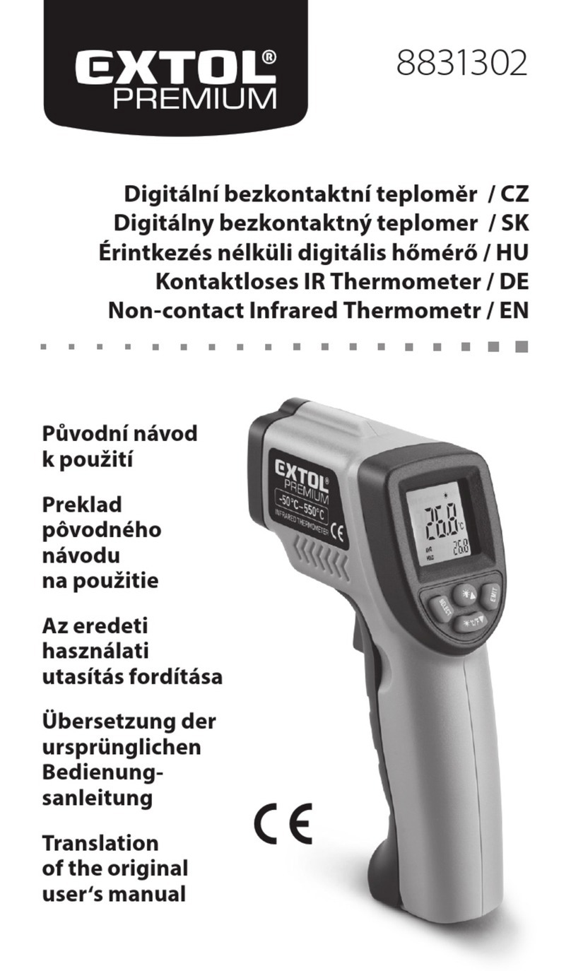
Sentest NP15 Series User manual


2
4 Software------------------------------ 11
4.1 System Requirements------------ 11
4.2 Installation and Connection----- 11
4.3 Starting the Software------------ 12
4.4 Download Logger Data---------- 12
5 Specifications------------------------ 13
6 Optical Charts------------------------ 14
7 Warranty----------------------------- 14
Table of Contents
Section Page Section Page
1 Introduction-------------------------- 3
1.1 User Interface-------------------- 3
1.2 Display--------------------------- 3
1.3 External Functions---------- -----4
2 Measurement------------------------ 4
2.1 Basic Operation------------------ 4
2.2 Battery Installation--------------- 4
2.3 Hold Function-------------------- 5
2.4 Laser Sighting -------------------- 5
2.5 Display Backlight ---------------- 5
2.6 Unit Settings --------------------- 5
Emissivity ---------------------------- 6
Max/ Min/ TC Probe------------------ 7
High/Low Alarm --------------------- 7
Tem pe ra tu re Un it -------------------- 9
Offset--------------------------------- 9
3 Data Logger-------------------------- 10
3.1 Storing Data---------------------- 10
3.2 Recall of Data -------------------- 10
3.3 Reset of the Data Logger -------- 10
*Note: Read the manual carefully
before the initial start-up. The
producer reserves the right to change
the herein described specifications in
case of technical advance of the
product.

3
1 Introduction
Thank you for choosing the NP15 infrared thermometer.
Read the manual carefully before the initial start-up. The producer reserves the right to change the herein described
specifications in case of technical advance of the product.
1.1 User Interface
A: LCD backlight
B: Laser symbol
C: Max/Min
D: High/Low alarm
E: Battery symbol
F: °C/ °F unit
G: IR temperature
H: Emissivity
I: Hold mode
J: TCK temperature
1.2 Display
[
∧
] Up/Laser:With this
button you can setup the
laser or increase the chosen
value or read MAX/MIN
result in [HOLD mode].
[
∨
] Down/Display backlight:
With this button to you can setup
the backlight or reduce the
chosen value.
[ ○ ] Mode Button:In [HOLD mode], each
time you press it, you will enter to another
function setup, e.g. press one time to enter to
emissivity setup, press it again will save
emissivity and enter to MIN/MAX setup and
so on.

4
1.3 External Functions
1. Laser/Optics
2. Tri gger
3. Battery Compartment
4. LCD Display
5. T/C Input
6. USB Port
2 Measurement
2.1 Basic Operation
Tu rn On: Press the trigger to turn on the unit and enter [Measurement mode].
Measuring: Aiming at a target, pull the trigger and keep it pressed.
The display will show the current temperature value.
Switch Off: The unit will automatically switch off after 7 seconds, if no button is pressed.
2.2 Battery Installation
The NP15 is equipped a 9V alkaline battery. If the battery is low the battery symbol will appear in the display.
Please exchange the battery immediately if the symbol is flashing.
1
2
3
4
5
6
Removing the battery cover
Replace the battery
Lifted up the battery cover
Loosen the screw
Sliding the battery snap
upward into compartment

5
2.3 Hold-Function
If you release the trigger, the unit enters to [HOLD mode]. The display will retain its last measurement for 7 seconds,
with the [HOLD] symbol appearing on the bottom left corner of the display. The unit automatically switches off after
this time if no button is pressed.
2.4 Laser Sighting
Pull the trigger (keep it pressed) and then press UP button [
∧
] to activate or deactivate the laser. The laser symbol
in the display (only if the trigger is pulled) indicates the active laser.
2.5 Display Backlight
Pull the Trigger (keep it pressed) and then press the DOWN button[
∨
] to activate/deactivate the display backlight.
2.6 Unit Settings
You can setup the emissivity, max/min/TCK display, high/low alarm, temperature unit, offset and trigger lock by
pressing the MODE button [ ○ ] in [HOLD mode]. The respective function will be flashing in the display. With the
UP [
∧
] and DOWN [
∨
] buttons, you can change parameters or activate/deactivate functions. To save the settings
you have to press the MODE button [ ○ ] again (will also switch to the next function) or pull the trigger to end the
setting. If you have not activated any button for 7 seconds, the instrument will not save the current modification and
shut down automatically.
WARNING: Do not point the laser directly at
the eyes of persons or animals! Do not stare into
the laser beam. Avoid indirect exposure via
reflective surfaces!

6
Release the trigger to enter to the [HOLD mode]. Each time you press the MODE button [ ○ ], the unit will switch
to next function interface in turn as follows. With the UP [
∧
] and DOWN [
∨
] buttons you can change parameters
or activate/ deactivate functions.
Emissivity (ε=)
In [HOLD mode], press the MODE button[ ○ ] to set the emissivity.
1) Emissivity (ε= ) flashing
2) Press UP [
∧
] or DOWN [
∨
] button to increase/reduce the emissivity.
3) To sav e t h e s et ti ng, press the MODE button [ ○ ] again (will also switch to the Max/ Min/ TC Probe function).
press MODE button [ ○ ]
(ε=) Emissivity
(MAX / MIN / )
(H ) High Alarm ON
High Alarm Value
(L ) Low Alarm ON
Low Alarm Value
(ºC/ºF) Temperature Unit
( ) Offset
(LOCH) Trigger Lock

7
Max/ Min/ TC Probe
In [HOLD mode], press the MODE button[ ○ ] repeatedly until enter into the Min/Max/TC probe mode. Press the
UP [
∧
] /DOWN[
∨
] button to setup which mode you want. MIN/MAX indicates the minimum/maximum value of
current measurement. The TC probe value will be displayed and continued measurement without pulling the
trigger, if a probe is connected. To save the setting, press the MODE button [ ○ ] again (will also switch to the High
Alarm function).
High/Low Alarm
1) High Alarm
In [HOLD mode], press the MODE button[ ○ ]until enter the High Alarm mode. To activate/deactivate High Alarm,
please press the UP [
∧
] or DOWN [
∨
] button if the ( H ) is shown in the display. The High Alarm function is activated
as soon as the display shows the sign (H ).

8
After pressing MODE button again, the High Alarm value can be adjusted using the UP [
∧
]or DOWN [
∨
]. To save
the setting, press the MODE button [ ○ ] again (will also switch to the Low Alarm function).
Low Alarm
In [HOLD mode], press the MODE button [ ○ ] until enter the Low Alarm mode. To activate/deactivate Low Alarm,
please press the UP [
∧
] or DOWN [
∨
] button if the ( L ) is shown in the display. The Low Alarm function is activated
as soon as the display shows the sign (L ).
After pressing MODE button again, the Low Alarm value can be adjusted using the UP [
∧
] or DOWN [
∨
]. To save
the setting, press the MODE button [ ○ ] again (will also switch to the Temperature Unit function).

9
Temperature Unit
Press the MODE button [ ○ ] enter to the temperature unit
mode, and press the UP [
∧
] or DOWN [
∨
] button to
toggle between °C and °F measurements. Press the MODE
button [ ○ ] again (will also switch to the Offset function).
Offset
In [HOLD mode], press the MODE button [ ○ ] repeatedly until enter the temperature Offset mode ( ). Then,
press the UP [
∧
] or DOWN [
∨
] button to setup the temperature offset value (±10). Press the MODE button [ ○ ]
again (will also return to the Trigger Lock function) or the trigger.
Trigger Lock
In [HOLD mode], press the MODE button [ ○ ] repeatedly
until enter the Tri gg er Lock mode (LOCH) and press the UP [∧]
or DOWN [∨] button to toggle between ON or OFF. To save
the setting, press the MODE button [ ○ ] again (will also
return to the Emissivity setting function) or the trigger.

10
3 Data Logger
The NP15 has an internal data logger for 2,000 points.
3.1 Storing Data
Press the trigger to turn on the unit and then release the trigger to enter to [HOLD mode], and press the DOWN [
∨
]
button, there will be a number #; MAX/disk icon appear above the current temperature result. The number # indicate
the memory position. You can choose the memory position from 1~2,000 with the UP[
∧
]/DOWN[
∨
] button.
Press the MODE button [ ○ ] can save the Max temperature of this measurement to the current position.
3.2 Recall of Data
In [Measurement mode], keep the trigger pressed and then press the MODE button [ ○ ] to recall the saved data.
The data logger position # and MAX/disc icon (flashing) will be shown in the display. Users can choose the memory
position by press the UP[
∧
] / DOWN[
∨
] button.
3.3 Reset of the Data Logger
Please press the DOWN [
∨
]button during the [HOLD mode]. Select logger
position 0 and press MODE button [ ○ ] again. Three buzzer signals confirm
the successful reset.

11
4 Software
The STonline software is specially developed for SENTEST infrared thermometers. Users can setup the unit; download the
logger data and recording temperature curve through the software.
4.1 System Requirements
- Operation system:XP, Vista or Win 7/8/10
- Hard disc with at least 30 MByte free space
- At least 128M RAM
- USB Interface
4.2 Install driver for USB Adapter
Please install the driver for Infrared Thermometer Adapter first. After connecting the NP15 through USB cable to
your PC, the system will allocate the infrared thermometer adapter driver automatically.
To f in d ou t wh ic h COM -Port number your computer set, open the device manager (Start – Settings – Control Panel
– System – Hardware – Device Manager). In the category "Ports (COM & LPT)" you can find the "Infrared
Thermometer Adapter (DR 6.x) ", only if the NP15 is plugged in. In parenthesis the COM Port number is shown.
4.3 STonline software
1) Please connect the NP15 to your PC and start STonline software, and open at first [Menu: Setup(S)\Interface
Settings], to choose the correct Com Port and set the Baud Rate to 115,200. After the unit connected to your
personal computer, and the STonline software is started successfully; the communication has been established.
The status line will be displayed in the left bottom: active COM port and successfully communication with the
connected sensor. And the target temperature will show on the left in digital form.

12
2) Starting the measurement
Please press the menu: [Measurement (M)\ Start]
3) Scaling of the temperature axis
In the menu item settings [Diagram (A)]
Global Auto Scaling: the temperature range of the diagram is automatically adapted to the respective peak values.
Local Auto Scaling: the temperature range of the diagram will be dynamically adapted to the respective peak values.
Manual scaling: It can be done at any time using the control elements of the temperature axis.
4) Stop the measurement
To st o p th e cu rre nt me asurement, please press the menu: [Measurement (M)\ Stop].
The save data [File (F)\Save Diagram] opens an explorer window to select destination and file name.
5) Diagram setting
The menu item settings [Diagram (A)\Settings] enable the settings for data diagram.
Color: temperature graph and digital display.
Initial Time Interval(S): time frame on x-axis at the beginning of measurement.
4.4 Download logger data
To do wn l oa d t he l og g er d at a f ro m t h e i nf r a re d t h ermo mete r, pl ea s e p re ss the download menu: [Measure (M)\Download
Data].

13
5 Specification
Model
NP15LT
NP15LR
NP15H1
NP15H2
NP15H3
Temperature Range
-30ºC~900ºC
-30ºC~1300ºC
600ºC~1600ºC
300ºC~1300ºC
100ºC~600ºC
Optics Resolution (90%)
60:1 (SF) / 75:1 (CF)
120 : 1
300 : 1
300 : 1
140:1 / 120:1 (FF)
Spectral Response
8~14μm
8~14μm
1μm
1.6μm
2.3μm
Response Time (95%)
300ms
300ms
5ms
5ms
5ms
Sighting
Dual Laser
Emissivity
0.10~1.00, ±0.01
Accuracy*
LT/LR : ≥ 20°C, ±1% of reading or ±1ºC, whichever is greater;
±1,5°C (-20 to 19.9°C), ±2,5°C (-30 to -20.1°C)
H1/H2/H3 : ±(0.5% of reading +2ºC)
Repeatability*
LT/LR:±0.5% of reading or ±0.5ºC, whichever is greater;H1/H2/H3:±(0.3% of reading +1ºC)
Configurations
Real time/Hold、Max/Min
Alarm Functions
HIGH/LOW alarm (audible & visible)
Data Logger
2,000 points
LCD Backlight
green and red/blue (alarm)
Digital Interface / Input
Mini USB / Type K : -40ºC~400ºC, accuracy : ±1% or ±1ºC, whichever is greater
Ambient Temperature
0ºC~50ºC
Relative Humidity
10%~95%, non-condensing
Power Supply
9V alkaline battery or USB
Dimensions/Weight
163.5(L) x207(W) x70(H)mm/470g
*At 23±5ºC, emissivity LT/LR=0.95,H1/H2/H3=1.00

14
6 Optical Charts
7 Warranty
Each product passes through a quality
process. Nevertheless, if a failure occurs please
contact the customer service at once. The period
of warranty starts from the date of delivery of the
product to the customer and shall cover a period
of 12 months. This warranty shall not apply to
fuses, batteries, or any product that has been
subject to misuse, neglect, accident, or abnormal
conditions of operation.
The manufacturer shall not be liable for any
special, incidental or consequential damages,
whether in contract, tort, or otherwise. If a failure
occurs during the warranty period, the product
will be replaced, calibrated or repaired without
further charges. The freight costs will be paid by
the sender. The manufacturer reserves the right
to exchange components of the product instead
of repairing it.
If the failure results from misuse, neglect,
accident, or abnormal conditions of operation or
storage, the user has to pay for the repair. In that
case you may ask for a cost estimate beforehand.
SENTEST Instruments Corporation Ltd.
Tel:+886-2-2579-5079
Fax:+886-2-2579-5297
www.sentest.com
NP15-E201707A
This manual suits for next models
4
Table of contents
