Digga HP450 User manual

OPERATOR’S MANUAL
HP450 / HP600
ROAD PROFILERS
FOR
SKID STEER LOADERS
PM-000068-A DECEMBER 2017

THIS PAGE
IS INTENTIONALLY
BLANK
PM-000068-A DECEMBER 2017

TABLE OF CONTENTS
PREFACE .................................................................................................................................. 3
SAFETY PRECAUTIONS
SAFETY STATEMENTS...................................................................................................................................... 4
GENERAL SAFETY PRECAUTIONS........................................................................................................ 4-6
EQUIPMENT SAFETYPRECAUTIONS.................................................................................................... 7-8
DECALS
DECAL PLACEMENT ................................................................................................................................. 9
DECALS..................................................................................................................................................10-11
PRE-OPERATION ........................................................................................................... 12-13
INSTALLATION ........................................................................................................................ 14-15
OPERATING INSTRUCTIONS
GENERAL OPERATING INSTRUCTIONS............................................................................................ 16-17
SPECIALAPPLICATIONS..................................................................................................................... 18-19
Large Area
Milling Around Manholes
Deep Cuts
Milling Taper Cuts
STORAGE ............................................................................................................................................... 20
LIFT POINTS.......................................................................................................................................... 20-21
TIE DOWN POINTS....................................................................................................................................21
MAINTENANCE AND SERVICE
LUBRICATION............................................................................................................................................ 22
ROUTINE MAINTENANCE......................................................................................................................... 23
PICK REPLACEMENT................................................................................................................................ 24
CHANGING THE DRUM............................................................................................................................. 25
CHANGING THE PLANETARY...................................................................................................................25-26
CHANGING THE HYDRAULIC MOTOR .................................................................................................... 26
CYLINDER SEAL REPLACEMENT....................................................................................................... 27-28
TROUBLESHOOTING .................................................................................................... 29-30
SPECIFICATIONS
BOLT TORQUE SPECIFICATIONS.............................................................................................................31
ROAD PROFILER SPECIFICATIONS........................................................................................................ 32
LIMITED WARRANTY ............................................................................................................. 35
PARTS..............................................................................................................................................33
PM-000068-A DECEMBER 2017
1

THIS PAGE
IS INTENTIONALLY
BLANK
PM-000068-A DECEMBER 2017
2

PREFACE
GENERAL COMMENTS
Congratulations on the purchase of your new DIGGA product! This product was carefully designed and
manufactured to give you many years ofdependable service. Only minor maintenance, such as cleaning
and lubricating, is required to keep it in top working condition. Be sure to observe all maintenance
procedures and safety precautions in this manual and on any safety decals located on the product and
on any equipment on which the attachment ismounted. This manual has been designed to help you do
a better, safer job. Read this manual carefully and become familiar with its contents.
WARNING! NEVER LET ANYONE OPERATE THIS UNIT WITHOUT READING THE "SAFETY
PRECAUTIONS" AND "OPERATING INSTRUCTIONS" SECTIONS OF THIS
MANUAL. ALWAYS CHOOSE HARD, LEVEL GROUND TO PARK THE VEHICLE ON
AND SET THE BRAKE SO THE UNIT CANNOT ROLL.
Unless noted otherwise, right and left sides are determined from the operator’s control position
when facing the attachment.
NOTE: The illustrations and data used in this manual were current (according to the information
available to us) at the time of printing, however, we reserve the right to redesign and change the
attachment as may be necessary without notification.
BEFORE OPERATION
The primary responsibility for safety with this equipment falls to the operator. Make sure the equipment
is operated onlyby trained individuals that have read and understand this manual. If there isany
portion of this manual orfunction you do not understand, contact your local authorized dealer or the
manufacturer to obtain further assistance. Keep this manual available for reference. Provide the
manual toany new owners and/or operators.
SAFETY ALERT SYMBOL
This is the “Safety Alert Symbol” used by this industry. This symbol is used to warn of
possible injury. Be sure to read all warnings carefully. They are included for your safety
and for the safety of others working with you.
SERVICE
Use only manufacturer replacement parts. Substitute parts may not meet the required standards.
Record the model and serial number ofyour unit. The parts department needs this information to
insure that you receive the correct parts.
SOUND AND VIBRATION
Sound pressure levels and vibration data for this attachment areinfluenced by many different
parameters: some items are listed below (not inclusive):
•prime mover type, age, condition, with or without cab enclosure andconfiguration
•operator training, behavior, stress level
•job site organization, working material condition, environment
Based on the uncertainty of the prime mover, operator, and job site, it is not possible to get precise
machine and operator sound pressure levels or vibration levels for this attachment.
PM-000068-A DECEMBER 2017
3

SAFETY STATEMENTS
THIS SYMBOL BY ITSELF OR WITH A WARNING WORD THROUGHOUT THIS
MANUAL IS USED TO CALL YOUR ATTENTION TO INSTRUCTIONS INVOLVING
YOUR PERSONAL SAFETY OR THE SAFETY OF OTHERS. FAILURE TO FOLLOW
THESE INSTRUCTIONS CAN RESULT OR DEATH.
DANGER
WARNING
CAUTION
NOTICE
THIS SIGNAL WORD INDICATES A HAZARDOUS SITUATION WHICH, IF
NOT AVOIDED, WILL RESULT IN DEATH OR SERIOUS INJURY.
THIS SIGNAL WORD INDICATES A HAZARDOUS SITUATION WHICH, IF
NOT AVOIDED, COULD RESULT IN DEATH OR SERIOUS INJURY.
THIS SIGNAL WORD INDICATES A HAZARDOUS SITUATION WHICH, IF
NOT AVOIDED, COULD RESULT IN MINOR OR MODERATE INJURY.
NOTICE IS USED TO ADDRESS PRACTICES NOT RELATED TO PHYSICAL
INJURY.
GENERAL SAFETY PRECAUTIONS
WARNING! READ MANUAL PRIOR TO INSTALLATION
Improper installation, operation, or maintenance of this equipment could result in
serious injury or death. Operators and maintenance personnel should read this
manual, aswell as allmanuals related tothis equipment and the prime mover
thoroughly before beginning installation, operation, ormaintenance. FOLLOW ALL
SAFETY INSTRUCTIONS IN THIS MANUAL AND THE PRIME MOVER’S
MANUAL(S).
READ AND UNDERSTAND ALL SAFETY STATEMENTS
Read all safety decals and safety statements in all manuals prior to operating or
working on this equipment. Know and obey allWHS regulations, local laws, and
other professional guidelines for your operation. Know and follow good work
practices when assembling, maintaining, repairing, mounting, removing, oroperating
this equipment.
KNOW YOUR EQUIPMENT
Know your equipment’s capabilities, dimensions, and operations before operating.
Visually inspect your equipment before you start, and never operate equipment that
is not inproper working order with all safety devices intact. Check allhardware to
ensure it issecure.Make certain that alllocking pins, latches, and connection
devices are properly installed and secured. Remove and replace any damaged,
fatigued, or excessively worn parts. Make certain all safety decals arein place and
are legible. Keep decals clean, and replace them ifthey become worn or hard to
read.
WARNING!
WARNING!
PM-000068-A DECEMBER 2017
4

WARNING!
WARNING!
WARNING!
GENERAL SAFETY PRECAUTIONS
PROTECT AGAINST FLYING DEBRIS
Always wear proper safety glasses, goggles ora face shield when driving pins in or
out, or when any operation causes dust, flying debris orany other hazardous
material.
LOWER OR SUPPORT RAISED EQUIPMENT
Do not work under raised booms without supporting them. Do not use support
material made ofconcrete blocks, logs, buckets, barrels, or any other material that
could suddenly collapse or shift positions. Make sure support material issolid, not
decayed, warped, twisted or tapered. Lower booms to ground level or on blocks.
Lower boomsand attachments tothe ground before leaving the cab or operator’s
station.
USE CARE WITH HYDRAULIC FLUID PRESSURE
Hydraulic fluid under pressure can penetrate the skin and cause serious injury or
death. Hydraulic leaks under pressure may not be visible. Before connecting or
disconnecting hydraulic hoses, read your prime mover’s operator’s manual for
detailed instructions on connecting and disconnecting hydraulic hosesor fittings.
•Keep unprotected body parts, such as face, eyes, and arms asfar awayas
possible from a suspected leak. Flesh injected with hydraulic fluid may develop
gangrene or other permanent disabilities.
•If injured by injected fluid, see a doctor at once. If your doctor is not familiar with
this type of injury, ask himto research it immediately to determine proper
treatment.
•Wear safety glasses, protective clothing and use a piece of cardboard or wood
when searching for hydraulic leaks. DO NOT USE YOUR HANDS! SEE
ILLUSTRATION.
CARDBOARD
HYDRAULIC HOSE
OR FITTING
MAGNIFYING GLASS
PM-000068-A DECEMBER 2017
5

GENERAL SAFETY PRECAUTIONS
WARNING!
WARNING!
DO NOT MODIFY MACHINE OR ATTACHMENTS
Modifications may weaken the integrity ofthe attachment and may impair the
function, safety, life and performance ofthe attachment. When making repairs, use
only the manufacturer’s genuine parts, following authorized instructions. Other parts
may be substandard in fit and quality. Never modify any ROPS (Roll Over
Protective Structure) or FOPS (Falling Object Protective Structure) equipment or
device. Any modifications must be authorized in writing by the manufacturer.
SAFELY MAINTAIN AND REPAIR EQUIPMENT
•Do not wear loose clothing or any accessories that can catch in moving parts. If
you have long hair, cover or secure it so that it does not become entangled in the
equipment.
•Work on a level surface in a well-lit area.
•Use properly grounded electrical outlets and tools.
•Use the correct tools for the job at hand. Make sure they are in good condition for
the task required.
•Wear the protective equipment specified by the tool manufacturer.
SAFELY OPERATE EQUIPMENT
Do not operate equipment until you are completely trained by a qualified
operator in how to use the controls, know its capabilities, dimensions and all
safety requirements. See your machine’s manual for these instructions.
•Keep all step plates, grab bars, pedals, and controls free of dirt, grease, debris
and oil.
•Never allow anyone to be around the equipment when it isoperating.
•Do not allow riders on the attachment or the prime mover.
•Do not operate the equipment from anywhere other than the correct operator’s
position.
•Never leave equipment unattended with the engine running, or with this
attachment in a raised position.
•Do not alter or remove any safety feature from the prime mover or this
attachment.
•Know your work site safety rules as well as traffic rules and flow. When in doubt
on any safety issue, contact your supervisor orsafety coordinator for an
explanation.
WARNING!
PM-000068-A DECEMBER 2017
6

WARNING!
WARNING!
WARNING!
WARNING!
EQUIPMENT SAFETY PRECAUTIONS
KNOW WHERE UTILITIES ARE
Observe overhead electrical and other utility lines. Be sure equipment will clear
them. When digging, call your local utilities for location of buried utility lines, gas,
water and sewer, as well as any other hazard you may encounter.
EXPOSURE TO RESPIRABLE CRYSTALLINE SILICA DUST
ALONG WITH OTHER HAZARDOUS DUSTS MAY CAUSE
SERIOUS OR FATAL RESPIRATORY DISEASE.
This attachment isdesigned to plane (mill) rock, concrete and asphalt, causing high
levels ofdust. It isrecommended to use dust suppression, dust collection and if
necessary personal protective equipment during the operation of the planer orofany
attachment that may cause high levels ofdust.
REMOVE PAINT BEFORE WELDING OR HEATING
Hazardous fumes/dust can be generated when paint isheated by welding, soldering
or using atorch. Do all work outside or in awell ventilated area and dispose of paint
and solvent properly. Remove paint before welding or heating.
When sanding orgrinding paint, avoid breathing the dust. Wear an approved
respirator. Ifyou use solvent or paint stripper, remove stripper with soap and water
before welding. Remove solvent or paint stripper containers and other flammable
material from area. Allow fumes to disperse at least 15 minutes before welding or
heating.
END OF LIFE DISPOSAL
At the completion of the useful life ofthe unit, drain all fluids and dismantle by
separating the different materials (rubber, steel, plastic, etc.). Follow all federal, state
and local regulations for recycling and disposal ofthe fluid and components.
OPERATING THE PROFILER
•Block off work area from bystanders, livestock, etc.
•Operate only from the operator’s station.
•Reduce speed when driving over rough terrain, on a slope, or turning, toavoid
overturning the vehicle.
•An operator must notuse drugs or alcohol, which can change his orher
alertness or coordination. An operator taking prescription or over-the-counter
drugs should seek medical advice on whether ornot he or she can safely
operate equipment.
•Before exiting the prime mover, lower the attachment to the ground, turn off the
prime mover’s engine, remove the key and apply the brakes.
•Be sure alldoors, guards and shields are in their proper position andsecurely
attached before operating the profiler.
WARNING!
PM-000068-A DECEMBER 2017
7

EQUIPMENT SAFETY PRECAUTIONS
TRANSPORTING THE PROFILER
•Travel only with the attachment in a safe transport position to prevent
uncontrolled movement. Drive slowly over rough ground and on slopes.
•When transporting on a trailer: Secure attachment at recommended tie down
locations using tie down accessories that are capable of maintaining attachment
stability.
•When driving on public roads use safety lights, reflectors and Slow Moving
Vehicle signs etc., to prevent accidents. Check local government regulations
that may affect you.
•Do not drive close to ditches, excavations, etc., cave in couldresult.
•Do not smoke when refueling the prime mover. Allow room in the fuel tank for
expansion. Wipe up any spilled fuel. Secure cap tightly when done.
MAINTAINING THE PROFILER
•Before performing maintenance, lower the attachment to the ground, turn off the
engine, remove the key and apply the brakes.
•Never perform any work on the attachment unless you are authorized and
qualified to do so. Always read the operator service manual’s before any repair
is made. After completing maintenance or repair, check for correct functioning of
the attachment. If not functioning properly, always tag “DO NOT OPERATE” until
all problems are corrected.
•Worn, damaged, or illegible safety decals must be replaced. New safety decals
can be ordered from DIGGA.
•Never make hydraulic repairs while the system is under pressure. Serious
personal injury or death could result.
•Never work under a raised attachment.
WARNING!
WARNING!
PM-000068-A DECEMBER 2017
8

GENERAL INFORMATION
DECALS
DECAL PLACEMENT
The diagram on this page shows the location of the decals used on the Road Profiler.
The decals areidentified by their partnumbers, with reductions of the actual decals located on
the following pages. Use this information to order replacements for lost or damaged decals. Be
sure to read alldecals before operating the attachment. They contain information you need to
know for both safety and product longevity.
IMPORTANT: Keep all safety decals clean and legible. Replace all missing, illegible, or damaged
safety decals. When replacing parts with safety decals attached, the safety decals must also be
replaced.
REPLACING SAFETY DECALS:Clean the area of application with nonflammable solvent, then wash
the same area with soap and water. Allow the surface to fully dry. Remove the backing from thesafety
decal, exposing the adhesive surface. Apply the safety decalto the position shown in the diagram
above and smooth out any bubbles.
SERIAL NUMBER
TAG LOCATION
MODEL NUMBER
#40113
#40149
#40149
#40161
#40719
#4468
#40161
MODEL NUMBER
#4468
#40161
#40118
#40723
#40722
#41043
#40151
OPERATION CONTROLS
PM-000068-A DECEMBER 2017
9
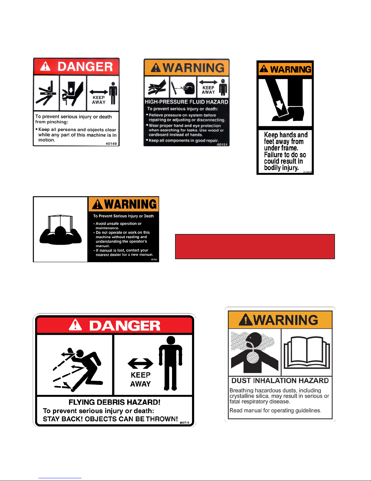
DECALS
DANGER! PINCH POINTS
PART #40149
WARNING! HIGH PRESSURE FLUID
PART #40151
WARNING!
PART #4468
WARNING! READ MANUAL
PART #40150
STAND CLEAR
PART #40161
DANGER! FLYING DEBRIS
PART #40719 (LARGE)
PART #40855 (SMALL)
WARNING! HAZARDOUS DUST
PART #41043
STAND CLEAR
PM-000068-A DECEMBER 2017
10

DECALS
*NOTE: Operation decals on hydraulically controlled units arepurchased according to the
multifunction electric control handle your unitisequipped with.
DEPTH INDICATOR
PART #40722
ANGLE INDICATOR
PART #40723
*OPERATION CONTROLS
PART #41196
CASE CONTROL HANDLE
*OPERATION CONTROLS
PART #41197
NEW HOLLAND CONTROL HANDLE
HP450
MODEL NUMBER HP450 (18" PLANER) PART
#40791
HP600
MODEL NUMBER HP600 (24" PLANER) PART
#40792
#41196
RIGHT
SHOE
LEFT
SHOE
SIDE
SHIFT
FORWARD
FLOW
REVERSE
FLOW
TILT
LEFT HANDLE RIGHT HANDLE
PLANER OPERATION
#41197
PLANER OPERATION
RIGHT
SHOE
LEFT
SHOE
SIDE
SHIFT
FORWARD
FLOW
REVERSE
FLOW
TILT
LEFT HANDLE RIGHT HANDLE
DIGGA LOGO
PART #DE-000047
PM-000068-A DECEMBER 2017
11

PRE-OPERATION
HIGH FLOW ROAD PROFILERS
SKID STEER
The DIGGA 450 & 600mm profilers are designed for use on high flow skid steers.
Road Profiler andskid steer compatibility is determined by the recommended lifting
capacity of your skid steer.
WARNING! DO NOT ATTACH OR OPERATE ANY ATTACHMENT THAT EXCEEDS THE
RECOMMENDED LIFTING CAPACITY OF YOUR SKID STEER.
Skid steers MUST be equipped with optional high flow, auxiliary boom
hydraulics, case drain and a multi-function electric control kit to run the
road profiler.
WARNING! EXPOSURE TO RESPIRABLE CRYSTALLINE SILICA DUST ALONG WITH OTHER
HAZARDOUS DUSTS MAY CAUSE SERIOUS OR FATAL RESPIRATORY
DISEASE. THIS ATTACHMENT IS DESIGNED TO PLANE (MILL) ROCK,
CONCRETE AND ASPHALT, CAUSING HIGH LEVELS OF DUST. IT IS
RECOMMENDED TO USE DUST SUPPRESSION, DUST COLLECTION AND IF
NECESSARY PERSONAL PROTECTIVE EQUIPMENT DURING THE OPERATION
OF THE PLANER OR OF ANY ATTACHMENT THAT MAY CAUSE HIGH LEVELS
OF DUST!
IMPORTANT
Concrete and masonry products contain silica sand. Quartz, which is a form ofsilica and the most
common mineral in the earth’s crust, isassociated with many types ofrock. Some activities that silica
dust may be present in the air include demolition, sweeping, loading, sawing, hammering, drilling or
planning of rock, concrete or masonry. It isrecommended to use dust suppression (such as water),
dust collection (such as a vacuum) along with personal protective equipment if necessary during the
operation of any attachment that may cause high levels of silica dust.
MOTOR OPTIONS LOW FLOW (80-106 LPM)
STD FLOW (110-130 LPM)
HIGH FLOW (136-166 LPM)
PM-000068-A DECEMBER 2017
12

PRE-OPERATION
HIGH FLOW ROAD PROFILERS
NOMENCLATURE
Throughout this manual, reference ismade tovarious attachment components. The purpose ofthis
section is to acquaint you with the various names of these components. This knowledge will be helpful
when reading through the manual orwhen ordering service parts.
SIDE SHIFT FRAME
RIGHT DEPTH CYLINDER
CONTROL VALVE
VALVE
COVER
LEFT DEPTH
CYLINDER
TILT CYLINDER
DEPTH INDICATOR EXTRACTING TOOL
(PICK REMOVER)
SIDE PLATE
FRONT ACCESS
DOOR
SIDE SHIFT CYLINDER
HYDRAULIC MOTOR
PLANETARY
WHEEL ASSEMBLY
PM-000068-A DECEMBER 2017
13

INSTALLATION INSTRUCTIONS
GENERAL INFORMATION
The following instructions will help mount your Profileronto your skidsteer loader. The
profiler uses the quick-attach system for ease ofinstallation. Therefore, ifyou know how to
attach your loader bucket, attaching the road profiler should prove no problem. Remember
to read all safety warnings, decals and operating instructions before operating the
attachment. Ifthere is any portion ofthis manual that you do not understand, contact your
dealer.
WARNING! THE 450MM & 600MM PROFILERS ARE DESIGNED FOR USE ON HIGH FLOW
HYDRAULIC SYSTEMS. DO NOT ATTACH OR OPERATE ANY ATTACHMENT
THAT EXCEEDS THE RECOMMENDED LIFTING CAPACITY OF YOUR SKID
STEER.
INSTALLATION INSTRUCTIONS
1. Remove the shipping banding from around the profiler and skid.
2. Remove any attachments from the front of the loader.
3. Following all standard safety practices and the instructions for installing an attachment in your
skid steer operator's manual, install the profiler onto your skid steer.
NOTE: It is important to make sure the locking mechanism on your quick attach is engaged, therefore
locking the attachment onto the skid steer.
4. Lower the unit to the ground and remove the key.
5. Relieve any pressure from the auxiliary hydraulic system. After making sure that there is not any
foreign matter on the hydraulic couplers connect the case drain coupler to the case drain on
your skid steer loader.
6. NOTE: The case drain line must be connected rst, then the power and return hoses. When
disconnecting the hoses, it is recommended to disconnect the case drain line last.
7. Connect the power and return couplers to the high ow auxiliary hydraulic system of your skid
steer loader. Route the hose in such a fashion as to avoid pinching or chang.
CAUTION! BE SURE CASE DRAIN COUPLER IS COMPLETELY ENGAGED. IMMEDIATE
HYDRAULIC MOTOR SEAL FAILURE AND PLANETARY DAMAGE WILL OCCUR IF
CASE DRAIN IS NOT SUCCESSFULLY CONNECTED.
8.Connect the electrical wire harness from the cold planer to the auxiliary electrical connector
on the front of the skid steer (if so equipped). If your skid steer is not equipped with an electrical
connector and you are using the DIGGA control handle, connect the wiring harness to the
control handle and place the control handle inside of the skid steer operator's station.
WARNING! DO NOT OPERATE THE ROAD PROFILER FROM OUTSIDE OF THE SKID STEER
OPERATOR'S STATION
PM-000068-A DECEMBER 2017
14

INSTALLATION INSTRUCTIONS
Following all standard safety practices, start the skid steer and run all cylinders through their full cycle
to purge any air from the system. Check that all controls function in accordance with the operating
control decal.
All profilers are equipped with a water nozzle kit to adapt them to your existing water line. Install the
female coupler supplied to your existing water line coming from the water tank on the skid steer.
Connect the female coupler to the male coupler on the profiler water nozzle kit.
NOTE: There is an optional cab mounted water kit available through your local dealer. Your profiler is
now installed and ready for operation.
DISCONNECT INSTRUCTIONS
1. Center the planer on the side shift frame.
2. Adjust depth and tilt setting to "0".
3. Set road profiler on a rm level surface.
4. Following Safety Shut Down Procedures; stop the engine and set the parking brake. Relieve any
pressure in the hydraulic lines.
5. Disconnect the power and return hoses from the auxiliary hydraulics. Disconnect the case drain
line.
6. Disconnect the electrical wire harness from the auxiliary electrical connector or the DIGGA
control handle and after turning the ball valve to the shut off position disconnect the water line at
the couplers.
7. Following all standard safety practices and the instructions for disconnecting an attachment in
your skid steer operator's manual, disconnect the profiler from your skid steer allowing the
mounting bracket to lower toward the ground as the skid steer is disengaged.
8. Connect the hydraulic couplers on the attachment together to prevent contaminants from
entering the hydraulic system.
PM-000068-A DECEMBER 2017
15
9.
10.
NOTE: It is recommended to disconnect the case drain line last.

OPERATING INSTRUCTIONS
INTENDED USE: This unitisdesigned toplane / mill horizontal surfaces consisting of rock,
concrete and asphalt. Use in any other way is considered contrary to the intended use.
GENERAL INFORMATION
The DIGGA Profiler attaches to the toolbar/quick-attach mechanism ofyour skid steer loader. Due to
this arrangement, thorough knowledge of the skid steercontrols isnecessary for machine operation.
Read and understand your skid steer operator's manual for information regarding skid steer
operation before attempting to use the profiler.Check the surface to be planed. The standard all
purpose picks can be used to mill bothasphalt and concrete. There are optional concrete picks that
are recommended ifthe profiler isto be used extensively for concrete. These picks do not perform as
well when milling asphalt, especially in warmer weather. Review the job at hand and determine the
required depth and tilt ofthe cut, and also the side shift position of the profiler.Best performance is
obtained when the road profiler isin the center position. Side shift should be used when visibility is a
determining factor, such as milling around manholes or when milling next to an obstacle such as a
building.
NOTE: Although the wheel assemblies are standard, they may be removed when distance is a factor
such as milling nexttoan obstacle or building.
WARNING! EXPOSURE TO RESPIRABLE CRYSTALLINE SILICADUST ALONG WITH OTHER
HAZARDOUS DUSTS MAY CAUSE SERIOUS OR FATAL RESPIRATORY
DISEASE. IT IS RECOMMENDED TO USE DUST SUPPRESSION, DUST
COLLECTION AND IF NECESSARY PERSONAL PROTECTIVE EQUIPMENT
DURING THE OPERATION OF THE PROFILER OR OF ANY ATTACHMENT
THAT MAY CAUSE HIGH LEVELS OF DUST.
OPERATING INSTRUCTIONS
1. Clear area ofallbystanders.
2. Lift the profiler until the drum is off the ground and start drum rotation. (Teeth at the bottom of
the drum must be moving in the same forward direction that the profiler travels).
DIRECTION OF
TRAVEL
NOTE: Mill only when the skid steer is traveling forward. Do not operate when traveling in reverse.
ROAD PROFILER
ROTATION
PM-000068-A DECEMBER 2017
16

OPERATING INSTRUCTIONS
NOTE: Hydraulic cylinders tilt the profiler,adjust the depth ofboththe left and right side of the
planer individually, and also shift the profiler tothe left orright.
3. Increase engine RPM and with the drum turning you can make any necessary
adjustments to the side shift. Do not side shift the road profiler during milling operation.
Once the desired side shift position has been achieved you are ready to begin. The
drum will not cut in a side to side motion. Tilt and Depth control can both be activated
during milling.
IMPORTANT: The drum MUST be turning to make any hydraulic adjustment to the profiler.
4. Position the profiler at the desired starting point. Set the left and right depth gauge tothe
desired depth mark on the profiler.Maximum depth of each cut isdetermined by the type of
material, the horsepower ofthe skid steer being used and the size of the profiler.It is
recommended for maximum performance that you start at approximately 19-25mm in concrete
and 38-50 mm in asphalt.
5. With the engine at full RPM and the profiler rolled back, lower the loader arms completely down
and slowly roll out the profiler until the weight ofthe profiler isresting on the rear wheel
assemblies. Continue to exert down pressure by rolling the loader forward until the front wheels
of the profiler areon the ground and the front wheels ofthe skid steer areraised approximately
50-75mm off the planing surface to assure sufficient pressure for stable operation.
NOTE: It is recommended to try a sample cut until the desired depth isachieved.
6. Slowly advance forward.
NOTE: If drum stalls you have been traveling too fast or cutting too deep. Back out ofthe cut until the
drum restarts (make necessary adjustments) and then continue operation.
NOTE: If the drum tends toride up out ofthe cut, decrease travel speed, be sure the profiler islevel
(front toback) and exert down pressure until the profiler isriding on the wheel assemblies. For
optimal cutting and reduced vibration, maintain down pressure on the profiler with all four profiler
wheels on the ground when cutting.
NOTE: Avoid side to side movement while planing as this may cause excessive drum wear or
planetary failure.
7. When you have reached the end ofthe pass, stop the skid steer and raise the profiler out ofthe
cut. Reposition skid steer for the nextcutand repeat steps 4, 5 & 6. Ifyouare not starting a
new cut, raise the profiler and retract the drum into the profiler housing using the depthcontrol
cylinders. Do not transport the profiler with drumturning.
PM-000068-A DECEMBER 2017
17

OPERATING INSTRUCTIONS
SPECIAL APPLICATIONS
LARGE AREA
DIGGA’S independent depth control design allows for continuous milling. Instead of planing pass
1,3, 5 and then going back and resetting the profiler for passes 2 and 4, the DIGGA profiler allows
for individual depth control from the operator's seat to enhance performance and continually mill
large areas.
MILLING AROUND MANHOLES
For bestvisibility when milling around
manholes itisrecommended that the
planer be shifted tothe right. The profiler
is not designed tomill around tight
corners, therefore itisrecommended that
four tosix passes be made on each side
of the manhole.
NOTE: The more passesthe less amount
of manual clean-up required.
1st PASS 1st PASS 2nd PASS 3rd PASS
3rd PASS MANUAL
CLEAN-UP
AREA
4th PASS 2nd PASS
MANHOLE
OR BASIN 1st PASS
PM-000068-A DECEMBER 2017
18
CAUTION! PERIODIC OBSERVATION MUST BE MADE OF THE TRANSMISSION OIL
TEMPERATURE INDICATOR WHEN PLANING WITH HIGH FLOW HYDRAULIC
SYSTEMS. DEPENDING ON THE AMBIENT TEMPERATURE AND THE DUTY CYCLE
OF THE MACHINE, HYDRAULIC OIL MAY OVERHEAT. IF INDICATOR COMES ON,
SHUT OFF THE ROAD PROFILER AND ALLOW THE SKID-STEER TO IDLE UNTIL
THE TEMPERATURE FALLS BELOW 70° CELSIUS.
IF THE SYSTEM CONTINUES RUNNING HOT IT MAY BE NECESSARY TO
CLEAN ANY DEBRIS FROM THE OIL COOLER AND RADIATOR. CHECK
ENGINE AIR FILTER AND ALSO THE HYDRAULIC OIL LEVEL.
CONTINUOUS OR EXCESSIVE OVERHEATING MAY CAUSE MACHINE DAMAGE.
This manual suits for next models
1
Table of contents
Other Digga Construction Equipment manuals


Popular Construction Equipment manuals by other brands


Zoomlion
Zoomlion QUY260 user manual

Link-Belt
Link-Belt HTC 8675 II Series Technical data

GP
GP HBM-NOBAS BG 160TA-4 Maintenance instructions

Husqvarna
Husqvarna FS400LV Operator's manual

Greenlee
Greenlee 880 Operation, service and parts instruction manual

SUNWARD
SUNWARD SWDM40 Operation & maintenance manual