Link-Belt HTC 8675 II Series Instruction manual

1
5852 (supersedes 5794)-0122-P9
HTC‐8675 IILink‐Belt Cranes
Technical Data
Specifications & Capacities
Telescopic Boom Truck Crane
75 US ton
70 metric ton
CAUTION: This material is supplied for
reference use only. Operator must refer to
in-cab Crane Rating Manual and Operator's
Manual to determine allowable crane lifting
capacities and assembly and operating
procedures.
Courtesy of CraneMarket.com


5852 (supersedes 5794)-0122-P9
HTC‐8675 IILink‐Belt Cranes
Table Of Contents
Boom, Attachments, and Upper Structure 1....................................................
Boom 1...................................................................................
Boom Wear Pads 1.......................................................................
Boom Head 1............................................................................
Boom Elevation 1.........................................................................
Auxiliary Lifting Sheave - Optional 1........................................................
Hook Blocks and Balls - Optional 1........................................................
Fly - Optional 1..........................................................................
Fly Extensions - Optional 1...............................................................
Upper Operator's Cab and Controls 1........................................................
Swing 2...................................................................................
Electrical 2................................................................................
Load Hoist System 3.......................................................................
Load Hoist Performance 3.................................................................
2M Main and Optional Auxiliary Winches 3...................................................
Hydraulic System 3........................................................................
Counterweight 3...........................................................................
Carrier 5....................................................................................
General 5.................................................................................
Outriggers 5...............................................................................
Steering and Axles 5.......................................................................
Suspension 5..............................................................................
Tires and Wheels 5.........................................................................
Brakes 5..................................................................................
Electrical 5................................................................................
Engine 5..................................................................................
Transmission 5............................................................................
Carrier Speeds and Gradeability 6.............................................................
Fuel Tank 6................................................................................
Hydraulic System 6........................................................................
Pump Drive 6..............................................................................
Lower Cab and Controls 7..................................................................
Additional Equipment 7.....................................................................
Axle Loads 8................................................................................
Axle Loads with 2-Axle or 3-Axle Boom Dolly 9...............................................
General Dimensions 10........................................................................
EPA 2021 10.................................................................................
General Dimensions 11........................................................................
Tier 3 / Stage IIIA 11..........................................................................
Working Range Diagram 12....................................................................
Courtesy of CraneMarket.com

5852 (supersedes 5794)-0122-P9
HTC-8675 II Link-Belt Cranes
Boom Extend Modes 13.......................................................................
Main Boom Lift Capacity Charts - Imperial B30.5 - Standard 14.................................
0 lb Counterweight - Fully Extended Outriggers - 360° Rotation 14...............................
0 lb Counterweight - On Tires - Stationary - Boom Centered Over Rear 15........................
0 lb Counterweight - On Tires - Pick & Carry (1 mph) - Boom Centered Over Rear 15..............
10,800 lb Counterweight - Fully Extended Outriggers - 360° Rotation 16...........................
10,800 lb Counterweight - On Tires - Stationary - Boom Centered Over Rear 17...................
10,800 lb Counterweight - On Tires - Pick & Carry (1 mph) - Boom Centered Over Rear 17.........
Main Boom Lift Capacity Charts - Imperial B30.5 - Optional 18.................................
14,400 lb Counterweight - Fully Extended Outriggers - 360° Rotation 18...........................
14,400 lb Counterweight - On Tires - Stationary - Boom Centered Over Rear 19...................
14,400 lb Counterweight - On Tires - Pick & Carry (1 mph) - Boom Centered Over Rear 19.........
18,400 lb Counterweight - Fully Extended Outriggers - 360° Rotation 20...........................
18,400 lb Counterweight - On Tires - Stationary - Boom Centered Over Rear 21...................
18,400 lb Counterweight - On Tires - Pick & Carry (1 mph) - Boom Centered Over Rear 21.........
Fly Attachment Lift Capacity Charts - Imperial B30.5 - Optional 22..............................
0 lb Counterweight - Fully Extended Outriggers - 360° Rotation 22...............................
98.7 ft Main Boom Length - 38 ft Offset Fly Length 22...........................................
127 ft Main Boom Length - 38 ft Offset Fly Length 23...........................................
10,800 lb Counterweight - Fully Extended Outriggers - 360° Rotation 24...........................
98.7 ft Main Boom Length 24.................................................................
127 ft Main Boom Length 26..................................................................
14,400 lb Counterweight - Fully Extended Outriggers - 360° Rotation 28...........................
98.7 ft Main Boom Length 28.................................................................
127 ft Main Boom Length 30..................................................................
18,400 lb Counterweight - Fully Extended Outriggers - 360° Rotation 32...........................
98.7 ft Main Boom Length 32.................................................................
127 ft Main Boom Length 34..................................................................
Main Boom Lift Capacity Charts - Metric B30.5 - Standard 36...................................
0t Counterweight - Fully Extended Outriggers - 360° Rotation 36.................................
0t Counterweight - On Tires - Stationary - Boom Centered Over Rear 37..........................
0t Counterweight - On Tires - Pick & Carry (1 km/h) - Boom Centered Over Rear 37...............
4.8t Counterweight - Fully Extended Outriggers - 360° Rotation 38...............................
4.8t Counterweight - On Tires - Stationary - Boom Centered Over Rear 39........................
4.8t Counterweight - On Tires - Pick & Carry (1 km/h) - Boom Centered Over Rear 39..............
Main Boom Lift Capacity Charts - Metric B30.5 - Optional 40...................................
6.4t Counterweight - Fully Extended Outriggers - 360° Rotation 40...............................
6.4t Counterweight - On Tires - Stationary - Boom Centered Over Rear 41........................
6.4t Counterweight - On Tires - Pick & Carry (1 km/h) - Boom Centered Over Rear 41..............
8.2t Counterweight - Fully Extended Outriggers - 360° Rotation 42...............................
8.2t Counterweight - On Tires - Stationary - Boom Centered Over Rear 43........................
8.2t Counterweight - On Tires - Pick & Carry (1 km/h) - Boom Centered Over Rear 43..............
Fly Attachment Lift Capacity Charts - Metric B30.5 - Optional 44................................
0t Counterweight - Fully Extended Outriggers - 360° Rotation 44.................................
30.1m Main Boom Length - 11.58m Offset Fly Length 44........................................
38.71m Main Boom Length - 11.58m Offset Fly Length 44.......................................
4.8t Counterweight - Fully Extended Outriggers - 360° Rotation 45...............................
30.1m Main Boom Length 45.................................................................
38.71m Main Boom Length 46................................................................
Courtesy of CraneMarket.com

5852 (supersedes 5794)-0122-P9
HTC‐8675 IILink‐Belt Cranes
6.4t Counterweight - Fully Extended Outriggers - 360° Rotation 47...............................
30.1m Main Boom Length 47.................................................................
38.71m Main Boom Length 48................................................................
8.2t Counterweight - Fully Extended Outriggers - 360° Rotation 49...............................
30.1m Main Boom Length 49.................................................................
38.71m Main Boom Length 50................................................................
Main Boom Lift Capacity Charts - Metric ISO - Optional 52.....................................
0t Counterweight - Fully Extended Outriggers - 360° Rotation 52.................................
0t Counterweight - On Tires - Stationary - Boom Centered Over Rear 53..........................
0t Counterweight - On Tires - Pick & Carry (1 km/h) - Boom Centered Over Rear 53...............
4.8t Counterweight - Fully Extended Outriggers - 360° Rotation 54...............................
4.8t Counterweight - On Tires - Stationary - Boom Centered Over Rear 55........................
4.8t Counterweight - On Tires - Pick & Carry (1 km/h) - Boom Centered Over Rear 55..............
Main Boom Lift Capacity Charts - Metric ISO - Optional 56.....................................
6.4t Counterweight - Fully Extended Outriggers - 360° Rotation 56...............................
6.4t Counterweight - On Tires - Stationary - Boom Centered Over Rear 57........................
6.4t Counterweight - On Tires - Pick & Carry (1 km/h) - Boom Centered Over Rear 57..............
8.2t Counterweight - Fully Extended Outriggers - 360° Rotation 58...............................
8.2t Counterweight - On Tires - Stationary - Boom Centered Over Rear 59........................
8.2t Counterweight - On Tires - Pick & Carry (1 km/h) - Boom Centered Over Rear 59..............
Fly Attachment Lift Capacity Charts - Metric ISO - Optional 60..................................
0t Counterweight - Fully Extended Outriggers - 360° Rotation 60.................................
30.1m Main Boom Length - 11.58m Offset Fly Length 60........................................
38.71m Main Boom Length - 11.58m Offset Fly Length 60.......................................
4.8t Counterweight - Fully Extended Outriggers - 360° Rotation 61...............................
30.1m Main Boom Length 61.................................................................
38.71m Main Boom Length 62................................................................
6.4t Counterweight - Fully Extended Outriggers - 360° Rotation 63...............................
30.1m Main Boom Length 63.................................................................
38.71m Main Boom Length 64................................................................
8.2t Counterweight - Fully Extended Outriggers - 360° Rotation 65...............................
30.1m Main Boom Length 65.................................................................
38.71m Main Boom Length 66................................................................
Courtesy of CraneMarket.com

1
5852 (supersedes 5794)-0122-P9
HTC‐8675 IILink‐Belt Cranes
Boom, Attachments, and Upper Structure
JBoom
Design - Four section, formed construction of extra high
tensile steel consisting of one base section and three tele
scoping sections. The two plate design of each section
has multiple longitudinal bends for superior strength. Each
telescoping section extends independently by means of
one double-acting, single stage hydraulic cylinder with in
tegrated holding valves.
Boom
S41-127 ft (12.5-38.71m) four section boom
SIntegral boom dolly connection
SFour boom extend modes (EM1 through EM4), controlled
from the operator's cab, provide superior capacities by
varying the extension of the telescoping sections:
SEM1 extends to 127.0 ft (38.71m)
SEM2 extends to 113.1 ft (34.5m)
SEM3 extends to 98.7 ft (30.1m)
SEM4 extends to 76.0 ft (23.2m)
SMechanical boom angle indicator
SMaximum tip height for each extend mode is:
SEM1 is 136 ft (41.5m)
SEM2 is 122 ft (37.3m)
SEM3 is 108 ft (33.0m)
SEM4 is 86 ft (26.2m)
Boom Wear Pads
SWear pads with Teflon inserts that self-lubricate the
boom sections
SBottom wear pads are universal for all boom sections
STop wear pads are universal for all boom sections
Boom Head
SFive 16.5 in (41.9cm) root diameter nylon sheaves to han
dle up to ten parts of line
SEasily removable wire rope guards
SRope dead end lugs on each side of the boom head
SBoom head is designed for quick-reeve of the hook
block
Boom Elevation
SOne double acting hydraulic cylinder with integral hold
ing valve
SBoom elevation: -3° to 80°
Auxiliary Lifting Sheave - Optional
SSingle 16.5 in (41.9m) root diameter nylon sheave
SEasily removable wire rope guards
SDoes not affect erection of the fly or use of the main head
sheaves
Hook Blocks and Balls - Optional
S40 ton (36.3mt) 4 sheave quick-reeve hook block with
safety latch
S60 ton (54.4mt) 4 sheave quick-reeve hook block with
safety latch
S75 ton (68.0mt) 5 sheave quick-reeve hook block with
safety latch
S8.5 ton (7.7mt) swivel and non-swivel hook balls with
safety latch
S10 ton (9.1mt) swivel and non-swivel hook balls with
safety latch
Fly - Optional
S38 ft (11.58m) one piece lattice fly, stowable, offsettable
to 2°, 15°, 30°, and 45°. Maximum tip height is 173 ft
(52.9m).
S38 ft-64 ft (11.58-19.51m) two piece bi-fold lattice fly,
stowable, offsettable to 2°, 15°, 30°, and 45°. Maximum
tip height is 199 ft (60.6m).
Fly Extensions - Optional
SOne 16 ft (4.88m) lattice extension, equipped with two
16.5 in (41.9cm) root diameter nylon sheaves, to be
mounted between the boom head and fly options. Maxi
mum tip height is 214 ft (65.4m). Minimum of 10,800 lb
(4.8t) of counterweight required.
STwo 16 ft (4.88m) lattice extensions, one equipped with
two 16.5 in (41.9cm) root diameter nylon sheaves, to be
mounted between the boom head and fly options. Maxi
mum tip height is 230 ft (70.2m). Minimum of 14,400 lb
(6.4t) of counterweight required.
JUpper Operator's Cab and Controls
Environmental Cab - Fully enclosed, one person cab of
galvaneal steel structure with acoustical insulation.
Equipped with:
STinted and tempered glass windows
SExtra-large fixed front window with windshield wiper and
washer
SSwing up roof window with windshield wiper
SSliding left side door with large fixed window
SSliding rear and right side windows for ventilation
SSix way adjustable, cushioned seat with seat belt and
storage compartment
SDiesel fired warm-water heater with air ducts for front
windshield defroster and cab floor
SDefroster fan for the front window
SBubble level
SCirculating fan
SAdjustable sun visor
SLED Dome light
SCup holder
SFire extinguisher
SLeft side viewing mirror
SPull-out cabwalk
STwo position travel swing lock
SAM/FM Radio
Air Conditioning - Optional - Integral with cab heating
system utilizing the same ventilation outlets
Engine Dependent Heater - Optional - Flameless,
warm-water system that does not have a separate fuel
tank
Armrest Controls - Two dual axis hydraulic joystick con
trollers or optional single axis hydraulic controllers for:
SCab heater and A/C controls
SSwing
SBoom hoist
SMain rear winch
SAuxiliary front winch - optional
SDrum rotation indication
SDrum rotation indicator activation switch
SSwing park brake switch
SWinch high/low speed and disable switch(es)
SWarning horn button
Courtesy of CraneMarket.com

25852 (supersedes 5794)-0122-P9
HTC‐8675 II Link‐Belt Cranes
Outrigger Controls - Hand held control box with umbilical
cord gives the operator the freedom to view operation while
setting the outriggers.
Foot Controls
SBoom telescope
SSwing brake
SEngine throttle
Right Front Console - Controls and indicators for:
SEngine ignition SBubble level
SEngine throttle lock S12 volt power connection
SPump enable SEmergency engine shutdown
SFunction disable SAir conditioning - optional
SFront windshield wiper SBoom floodlight - optional
and washer SRotating beacon or strobe
SCab floodlights light - optional
SWarning horn SThird wrap selector switch -
SConsole dimmer switch optional
Camera Display - Located on dash console
SDisplays right side of upper
SDisplays main and auxiliary winches
Cab Instrumentation - Ergonomically positioned LCD
display, CANBUS instrumentation for crane operation in
cluding:
STachometer SEngine oil pressure
SEngine water temperature SSwing park brake light
SFuel level SBattery voltage
SHydraulic oil temperature SFuel rate (gal/hr)
SStop engine SEngine load
SCheck engine SEngine Diagnostics
SRegeneration disabled light (EPA 2021 engine only)
SDPF regeneration light (EPA 2021 engine only)
SHigh exhaust temperature light (EPA 2021 engine only)
SMalfunction indicator lamp (EPA 2021 engine only)
SEngine air filter high restriction light
LinkBelt Pulse – The LinkBelt inhouse designed, total
crane operating system that utilizes the display as a
readout and operator interface for the following systems:
SRated capacity limiter – LCD graphic audio – visual
warning system integrated into the dash with anti – two
block and function limiter. Operating data includes:
SCrane configuration
SBoom length and angle
SBoom head height
SAllowed load and % of allowed load
SRCL light bar
SBoom angle
SRadius of load
SActual load
SWind speed
SHighlighted unit of measurement on working screen
SActive pin/latch status
STelescope operation displayed in real time
SThird wrap indicator
SDiagnostics
SOperator settable alarms (include):
SMaximum and minimum boom angles
SMaximum tip height
SMaximum boom length
SSwing left/right positions
SOperator defined area (imaginary plane)
STelematics – Cellular-based data logging and
monitoring system that provides:
SLocation and operational settings
SRoutine maintenance
SCrane and engine monitoring
SDiagnostic and fault codes
SExtend control module (ECM)
SControls the extend modes
SDiagnostics
Integrated Third Wrap Indicator - Optional - Link-Belt
Pulse color display visually and audibly warns the operator
when the wire rope is on the first/bottom layer and when
the wire rope is down to the last three wraps.
Integrated Third Wrap Function Kickout - Optional -
Link-Belt Pulse color display visually and audibly warns
the operator when the wire rope is on the first/bottom layer
and provides a function kickout when the wire rope is down
to the last three wraps.
Internal RCL Light Bar - Visually informs the operator
when crane is approaching maximum load capacity with a
series of green, yellow, and red lights.
External RCL Light Bar - Optional - Visually informs the
ground crew when crane is approaching maximum load
capacity with a series of green, yellow, and red lights.
JSwing
Motor/Planetary - Bi-directional hydraulic swing motor
mounted to a planetary reducer for 360° continuous
smooth swing at 1.9 rpm.
Swing Park Brake - 360°, electric over hydraulic, (spring
applied/hydraulic released) multi-disc brake mounted on
the speed reducer. Operated by a switch from the opera
tor's cab.
Swing Brake - 360°, foot operated, hydraulic applied disc
brake mounted to the speed reducer.
Swing Lock - Two-position swing lock (boom over front
or rear) operated from the operator's cab.
360° Positive Swing Lock - Optional - Meets New York
City requirement.
JElectrical
Swing Alarm - Audio warning device signals when the up
per is swinging.
Lights
STwo LED working lights on front of the cab
SOne LED working light on the top of the cab - optional
SOne amber strobe beacon on top of the cab - optional
SBoom floodlight - Single - optional
SBoom floodlight - Dual - optional
SBoom floodlight - High intensity remote controlled -
optional
Courtesy of CraneMarket.com

3
5852 (supersedes 5794)-0122-P9
HTC‐8675 IILink‐Belt Cranes
JLoad Hoist System
Load Hoist Performance
Main (Rear) and Auxiliary (Front) Winches - 3/4 in (19mm) Rope
Maximum Line Pull Normal Line Speed High Line Speed Layer Total
Layer lb kN ft/min m/min ft/min m/min ft mft m
1 16,880 75.09 172 52.4 341 104.0 114 34.7 114 34.7
2 15,519 69.03 187 57.0 371 113.1 124 37.8 238 72.5
3 14,362 63.89 202 61.6 401 122.2 134 40.8 372 113.4
4 13,365 59.45 217 66.1 430 131.1 144 43.9 516 157.3
5 12,497 55.59 232 70.7 460 140.2 154 46.9 670 204.2
6 --- --- --- --- --- --- 164 50.0 834 254.2
Wire Rope Application Diameter Type
Maximum
Permissible Load
in mm lb kN
Main (Rear) Winch Standard 3/4 19 37x7 non rotating - right lang lay (Type KC) 16,000 71.17
Optional 3/4 19 36x7 rotation resistant - right regular lay (Type ZB) 15,600 69.39
Auxiliary (Front)
Winch
Standard 3/4 19 37x7 non rotating - right lang lay (Type KC) 16,000 71.17
Optional 3/4 19 36x7 rotation resistant - right regular lay (Type ZB) 15,600 69.39
2M Main and Optional Auxiliary Winches
SAxial piston, full and half displacement (2-speed) motors
driven through planetary reduction unit for positive con
trol under all load conditions.
SGrooved lagging
SPower up/down mode of operation
SHoist drum cable follower - optional
SDrum rotation indicator
SDrum diameter: 16 in (40.6cm)
SRope length:
SMain: 670 ft (204.2m)
SAuxiliary: 500 ft (152.4m) or 670 ft (204.2m)
SMaximum rope storage: 834 ft (254.2m)
STerminator style socket and wedge
JHydraulic System
All circuits of the hydraulic system are pressure compen
sated.
Counterbalance Valves - All hoist motors, boom extend
cylinders, and boom hoist cylinders are equipped with
counterbalance valves to provide load lowering and to pre
vent accidental load drop if hydraulic power is suddenly re
duced.
Hydraulic Oil Cooler - One carrier mounted cooler re
moves heat from the hydraulic oil. The cooler is mounted
in left side access ladder.
Boom Hoist Float Valves (Optional) - For transporting
the boom over the rear of the crane with a boom dolly. Al
lows hydraulic oil within the boom hoist cylinder to flow be
tween piston side and case side, allowing the boom to float
while on the boom dolly.
Swing Brake Release - For transporting the boom over
the rear of the crane with a boom dolly. Holds the 360º
swing park brake in the released position allowing free
rotation of the upper structure.
JCounterweight
Standard - Total of 10,800 lb (4.8t) of total counterweight
consisting of three, hydraulically removable counter
weights. Assembled and disassembled by hydraulic cylin
ders controlled from the left and right side of the upper
structure with capacities for:
S0 lb (0t) counterweight
S3,600 lb (1.6t) counterweight
S7,200 lb (3.2t) counterweight
S10,800 lb (4.8t) counterweight
Optional - 3,600 lb (1.6t) in addition to standard coun
terweight for a total of 14,400 lb (6.4t) with additional ca
pacities for:
S14,400 lb (6.4t) counterweight
Optional - 7,600 lb (3.4t) in addition to standard coun
terweight for a total of 18,400 lb (8.2t) with additional ca
pacities for:
S14,400 lb (6.4t) counterweight
S18,400 lb (8.2t) counterweight*
Low speed jobsite travel is offered for these optional counter
weight configurations and a boom dolly or boom trailer may
be required for on-highway travel.
* Overall width of the crane increases to 10 ft 5 in (3.2m)
for this counterweight configuration
Courtesy of CraneMarket.com

45852 (supersedes 5794)-0122-P9
HTC‐8675 II Link‐Belt Cranes
10,800 lb (4.8t)14,400 lb (6.4t)
18,400 lb (8.2t)
C
2,000 lb
(0.9t)
Piece
B
3,600 lb
(1.6t)
Piece
A
3,600 lb
(1.6t)
Piece
A
3,600 lb
(1.6t)
Piece
A
3,600 lb
(1.6t)
Piece
A
3,600 lb
(1.6t)
Piece
B
3,600 lb
(1.6t)
Piece
A
3,600 lb
(1.6t)
Piece
A
3,600 lb
(1.6t)
Piece
A
3,600 lb
(1.6t)
Piece
D
2,000 lb
(0.9t)
Piece
A
3,600 lb
(1.6t)
Piece
A
3,600 lb
(1.6t)
Piece
Counterweight
Packages
10,800 lb (4.9t) - Standard
14,400 (6.4t) - Optional
18,400 (8.2t) - Optional
Counterweight
Pieces
A
3,600 lb
(1.6t)
Piece
A
3,600 lb
(1.6t)
Piece
A
3,600 lb
(1.6t)
Piece
B
3,600 lb
(1.6t)
Piece
C
2,000 lb
(0.9t)
Piece
D
2,000 lb
(0.9t)
Piece
Counterweight
Configurations
0 lb
(0t)
A3,600 lb
(1.6t)X
A,A 7,200 lb
(3.2t)X X
A,A,A 10,800 lb
(4.8t)X X X
A,A,A,B 14,400 lb
(6.4t)X X X X
A,A,A,B,C,D 18,400 lb
(8.2t)X X X X X X
Courtesy of CraneMarket.com
5
5852 (supersedes 5794)-0122-P9
HTC‐8675 IILink‐Belt Cranes
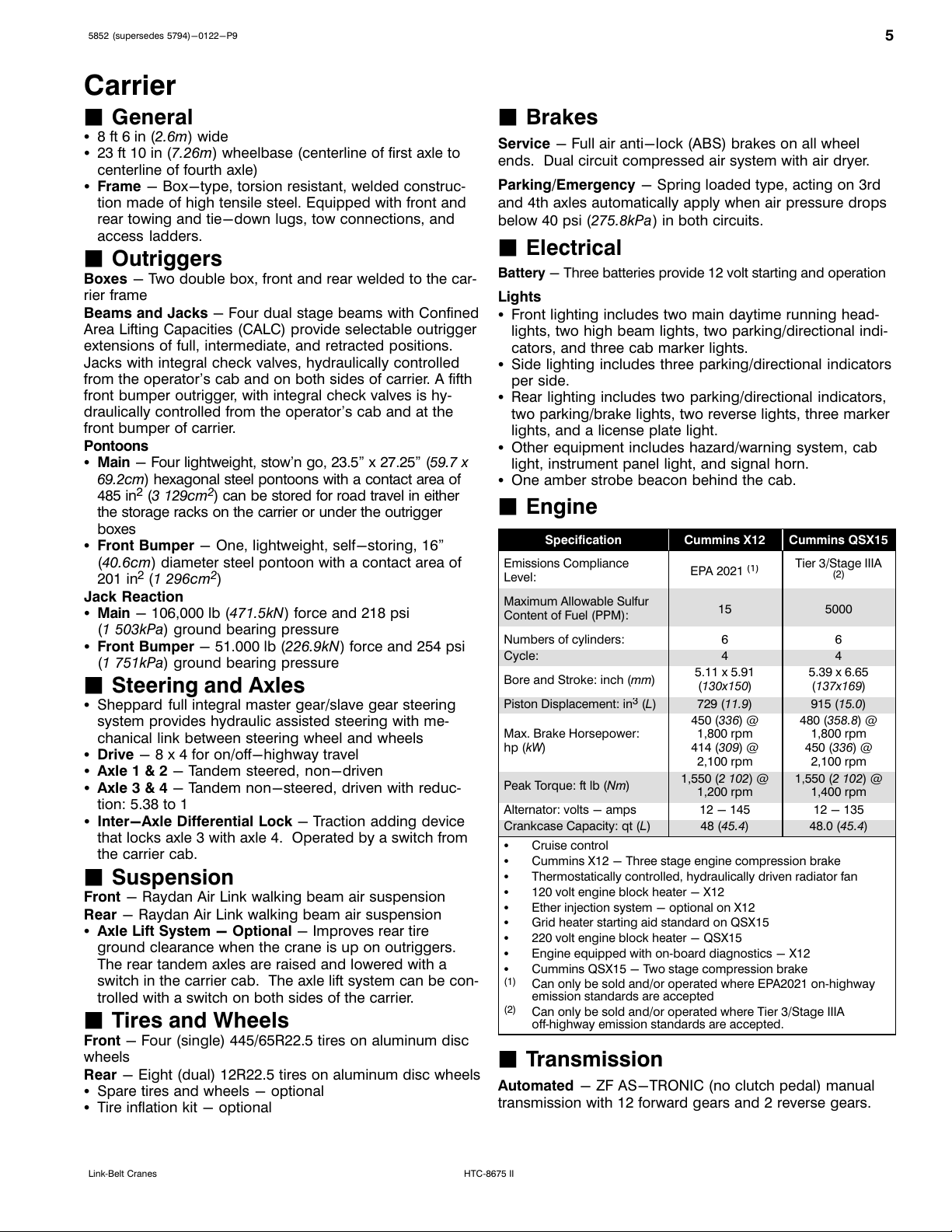
Carrier
JGeneral
S8 ft 6 in (2.6m) wide
S23 ft 10 in (7.26m) wheelbase (centerline of first axle to
centerline of fourth axle)
SFrame - Box-type, torsion resistant, welded construc
tion made of high tensile steel. Equipped with front and
rear towing and tie-down lugs, tow connections, and
access ladders.
JOutriggers
Boxes - Two double box, front and rear welded to the car
rier frame
Beams and Jacks - Four dual stage beams with Confined
Area Lifting Capacities (CALC) provide selectable outrigger
extensions of full, intermediate, and retracted positions.
Jacks with integral check valves, hydraulically controlled
from the operator's cab and on both sides of carrier. A fifth
front bumper outrigger, with integral check valves is hy
draulically controlled from the operator's cab and at the
front bumper of carrier.
Pontoons
SMain - Four lightweight, stow'n go, 23.5” x 27.25” (59.7 x
69.2cm) hexagonal steel pontoons with a contact area of
485 in2(3 129cm2) can be stored for road travel in either
the storage racks on the carrier or under the outrigger
boxes
SFront Bumper - One, lightweight, self-storing, 16”
(40.6cm) diameter steel pontoon with a contact area of
201 in2(1 296cm2)
Jack Reaction
SMain - 106,000 lb (471.5kN) force and 218 psi
(1 503kPa) ground bearing pressure
SFront Bumper - 51.000 lb (226.9kN) force and 254 psi
(1 751kPa) ground bearing pressure
JSteering and Axles
SSheppard full integral master gear/slave gear steering
system provides hydraulic assisted steering with me
chanical link between steering wheel and wheels
SDrive - 8 x 4 for on/off-highway travel
SAxle 1 & 2 - Tandem steered, non-driven
SAxle 3 & 4 - Tandem non-steered, driven with reduc
tion: 5.38 to 1
SInter-Axle Differential Lock - Traction adding device
that locks axle 3 with axle 4. Operated by a switch from
the carrier cab.
JSuspension
Front - Raydan Air Link walking beam air suspension
Rear - Raydan Air Link walking beam air suspension
SAxle Lift System - Optional - Improves rear tire
ground clearance when the crane is up on outriggers.
The rear tandem axles are raised and lowered with a
switch in the carrier cab. The axle lift system can be con
trolled with a switch on both sides of the carrier.
JTires and Wheels
Front - Four (single) 445/65R22.5 tires on aluminum disc
wheels
Rear - Eight (dual) 12R22.5 tires on aluminum disc wheels
SSpare tires and wheels - optional
STire inflation kit - optional
JBrakes
Service - Full air anti-lock (ABS) brakes on all wheel
ends. Dual circuit compressed air system with air dryer.
Parking/Emergency - Spring loaded type, acting on 3rd
and 4th axles automatically apply when air pressure drops
below 40 psi (275.8kPa) in both circuits.
JElectrical
Battery - Three batteries provide 12 volt starting and operation
Lights
SFront lighting includes two main daytime running head
lights, two high beam lights, two parking/directional indi
cators, and three cab marker lights.
SSide lighting includes three parking/directional indicators
per side.
SRear lighting includes two parking/directional indicators,
two parking/brake lights, two reverse lights, three marker
lights, and a license plate light.
SOther equipment includes hazard/warning system, cab
light, instrument panel light, and signal horn.
SOne amber strobe beacon behind the cab.
JEngine
Specification Cummins X12 Cummins QSX15
Emissions Compliance
Level: EPA 2021
(1)
Tier 3/Stage IIIA
(2)
Maximum Allowable Sulfur
Content of Fuel (PPM): 15 5000
Numbers of cylinders: 6 6
Cycle: 4 4
Bore and Stroke: inch (mm)5.11 x 5.91
(130x150)
5.39 x 6.65
(137x169)
Piston Displacement: in
3
(L)729 (11.9)915 (15.0)
Max. Brake Horsepower:
hp (kW)
450 (336) @
1,800 rpm
414 (309) @
2,100 rpm
480 (358.8) @
1,800 rpm
450 (336) @
2,100 rpm
Peak Torque: ft lb (Nm)1,550 (2 102) @
1,200 rpm
1,550 (2 102) @
1,400 rpm
Alternator: volts - amps 12 - 145 12 - 135
Crankcase Capacity: qt (L)48 (45.4)48.0 (45.4)
SCruise control
SCummins X12 - Three stage engine compression brake
SThermostatically controlled, hydraulically driven radiator fan
S120 volt engine block heater - X12
SEther injection system - optional on X12
SGrid heater starting aid standard on QSX15
S220 volt engine block heater - QSX15
SEngine equipped with on‐board diagnostics - X12
SCummins QSX15 - Two stage compression brake
(1) Can only be sold and/or operated where EPA2021 on‐highway
emission standards are accepted
(2) Can only be sold and/or operated where Tier 3/Stage IIIA
off‐highway emission standards are accepted.
JTransmission
Automated - ZF AS-TRONIC (no clutch pedal) manual
transmission with 12 forward gears and 2 reverse gears.
Courtesy of CraneMarket.com

65852 (supersedes 5794)-0122-P9
HTC‐8675 II Link‐Belt Cranes
JCarrier Speeds and Gradeability
ZF Astronic
Governed Speed Gradeability
(@ Peak Torque
Except Creep @ Idle)
EPA 2021 Tier 3/Stage IIIA
Gear Ratio mph km/h mph km/h
% Grade
EPA 2021 Tier 3/
Stage IIIA
12th 0.78 62.9 101.2 62.8 101.1 3.1 2.1
11th 1.00 48.9 78.7 48.9 78.7 3.9 3.3
10th 1.27 38.6 62.1 38.6 62.1 5.0 4.6
9th 1.63 30.0 48.3 30.0 48.3 6.4 6.2
8th 2.10 23.3 37.5 23.3 37.4 8.3 8.3
7th 2.70 18.1 29.1 18.1 29.1 10.6 10.9
6th 3.55 13.8 22.2 13.8 22.1 14.0 14.6
5th 4.57 10.7 17.2 10.7 17.2 17.9 19.0
4th 5.78 8.5 13.7 8.5 13.6 22.7 24.3
3rd 7.44 6.6 10.6 6.6 10.6 29.2 31.4
2nd 9.59 5.1 8.2 5.1 8.2 37.7 40.7
1st 12.33 4.0 6.4 4.0 6.4 48.4 52.4
Reverse 1 11.41 4.3 6.9 4.3 6.9 44.9 48.5
Reverse 2 8.88 5.5 8.9 5.5 8.9 34.9 37.6
Creep @ idle
2nd 9.59 1.7 2.7 1.7 2.7 19.5 28.8
1st 12.33 1.3 2.1 1.3 2.1 25.0 37.2
Reverse 1 11.41 1.4 2.3 1.4 2.3 23.2 34.4
Reverse 2 8.88 1.8 3.0 1.8 3.0 18.0 26.6
Based on a gross vehicle weight of 95,000 lb (43 091.3kg)
JFuel Tank
SOne 95 gal (359.6L) capacity tank
SOne 10 gal (37.8L) capacity diesel exhaust fluid (DEF) plastic
tank
JHydraulic System
All functions are hydraulically powered allowing positive,
precise control with independent or simultaneous operation
of all functions.
Main Pumps
SThree fixed displacement gear pumps with automatic
disconnect for the main and auxiliary winches, swing,
boom hoist, control circuit, and telescope for use when
pick & carry switch is in travel mode.
SOne fixed displacement gear pump for steering and the
front bumper outrigger
STwo fixed displacement gear pumps for engine cooling
fan and main outriggers. These pumps also provide flow
to the winches and boom hoist for “pick & carry” mode.
Operated by a switch in the carrier cab.
SCombined pump capacity of 188 gpm (711.7Lpm)
Hydraulic Reservoir - 144 gal (545.1L) capacity equipped
with sight level gauge. Diffusers built in for deaeration.
Filtration - One 10 micron, full flow, return line filter. All oil
is filtered prior to return to reservoir. Accessible for easy fil
ter replacement.
JPump Drive
All pumps are mechanically driven by the diesel engine.
Main and auxiliary winches, swing, boom hoist, control cir
cuit, and telescope pumps are mounted to an automatic
pump disconnect on the rear of the transmission to aid in
cold weather starting as well as to reduce pump wear while
traveling.
Courtesy of CraneMarket.com
7
5852 (supersedes 5794)-0122-P9
HTC‐8675 IILink‐Belt Cranes
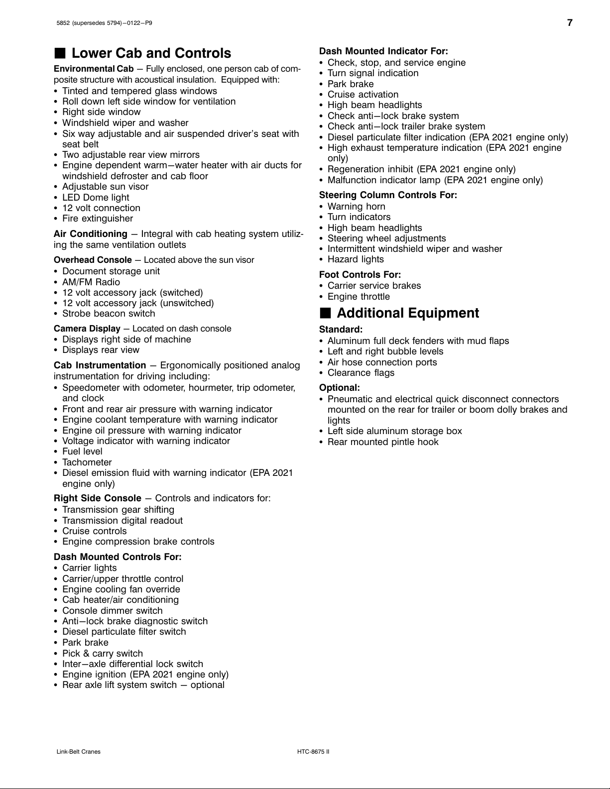
JLower Cab and Controls
Environmental Cab - Fully enclosed, one person cab of com
posite structure with acoustical insulation. Equipped with:
STinted and tempered glass windows
SRoll down left side window for ventilation
SRight side window
SWindshield wiper and washer
SSix way adjustable and air suspended driver's seat with
seat belt
STwo adjustable rear view mirrors
SEngine dependent warm-water heater with air ducts for
windshield defroster and cab floor
SAdjustable sun visor
SLED Dome light
S12 volt connection
SFire extinguisher
Air Conditioning - Integral with cab heating system utiliz
ing the same ventilation outlets
Overhead Console - Located above the sun visor
SDocument storage unit
SAM/FM Radio
S12 volt accessory jack (switched)
S12 volt accessory jack (unswitched)
SStrobe beacon switch
Camera Display - Located on dash console
SDisplays right side of machine
SDisplays rear view
Cab Instrumentation - Ergonomically positioned analog
instrumentation for driving including:
SSpeedometer with odometer, hourmeter, trip odometer,
and clock
SFront and rear air pressure with warning indicator
SEngine coolant temperature with warning indicator
SEngine oil pressure with warning indicator
SVoltage indicator with warning indicator
SFuel level
STachometer
SDiesel emission fluid with warning indicator (EPA 2021
engine only)
Right Side Console - Controls and indicators for:
STransmission gear shifting
STransmission digital readout
SCruise controls
SEngine compression brake controls
Dash Mounted Controls For:
SCarrier lights
SCarrier/upper throttle control
SEngine cooling fan override
SCab heater/air conditioning
SConsole dimmer switch
SAnti-lock brake diagnostic switch
SDiesel particulate filter switch
SPark brake
SPick & carry switch
SInter-axle differential lock switch
SEngine ignition (EPA 2021 engine only)
SRear axle lift system switch - optional
Dash Mounted Indicator For:
SCheck, stop, and service engine
STurn signal indication
SPark brake
SCruise activation
SHigh beam headlights
SCheck anti-lock brake system
SCheck anti-lock trailer brake system
SDiesel particulate filter indication (EPA 2021 engine only)
SHigh exhaust temperature indication (EPA 2021 engine
only)
SRegeneration inhibit (EPA 2021 engine only)
SMalfunction indicator lamp (EPA 2021 engine only)
Steering Column Controls For:
SWarning horn
STurn indicators
SHigh beam headlights
SSteering wheel adjustments
SIntermittent windshield wiper and washer
SHazard lights
Foot Controls For:
SCarrier service brakes
SEngine throttle
JAdditional Equipment
Standard:
SAluminum full deck fenders with mud flaps
SLeft and right bubble levels
SAir hose connection ports
SClearance flags
Optional:
SPneumatic and electrical quick disconnect connectors
mounted on the rear for trailer or boom dolly brakes and
lights
SLeft side aluminum storage box
SRear mounted pintle hook
Courtesy of CraneMarket.com

85852 (supersedes 5794)-0122-P9
HTC‐8675 II Link‐Belt Cranes
Axle Loads
Base crane with full tank of fuel
and no counterweight
Gross Vehicle
Weight (1)Front Axles Rear Axles
lb kg lb kg lb kg
EPA 2021 74,786 33 922 35,134 15 937 39,652 17 986
Tier 3/Stage IIIA 74,452 33 771 34,833 15 800 39,600 17 962
Driver in carrier cab 250 113 315 143 -65 -29
Rear pintle hook 13 6-6 -3 19 8
Pneumatic and electrical connectors for trailer or boom dolly 11 5-2 -1 13 6
Carrier aluminum storage box 60 27 28 13 32 14
Air ride lift system - rear axles 47 21 0047 21
Ether injection 5263-1 -1
Hoist drum follower - main 76 34 -43 -19 119 54
Auxiliary winch with 500 ft (152.4m) of 3/4” (19mm) type “RB” rope 652 296 -238 -108 890 404
Hoist drum follower - auxiliary 76 34 -32 -14 108 49
Substitute 500 ft (152.4m) of rope with 670 ft (204.2m) of rope - auxiliary 213 97 -77 -35 290 132
Remove 670 ft (204.2m) of rope from rear (main) winch -856 -388 439 199 -1,295 -587
Remove 500 ft (152.4m) of rope from front (auxiliary) winch -643 -292 233 106 -876 -397
Air conditioner - operator's cab 217 98 -15 -7 232 105
360° mechanical swing lock 140 64 21 9119 54
3,600 lb (1.6t) counterweight on upper - 1 piece 3,652 1 657 -1,796 -815 5,448 2 471
7,200 lb (3.2t) counterweight on upper - 2 pieces 7,304 3 313 -3,593 -1 630 10,897 4 943
10,800 lb (4.8t) counterweight on upper - 3 pieces 10,956 4 970 -5,389 -2 444 16,345 7 414
14,400 lb (6.4t) counterweight on upper - 4 pieces 14,608 6 626 -7,185 -3 259 21,793 9 885
Floodlight to the front of boom base section 9410 4-1 0
Fly mounting brackets to boom base section for fly options 176 80 136 62 40 18
38 ft (11.58m) offsettable fly - stowed 1,671 758 1,758 798 -87 -40
38-64 ft (11.58-19.51m) offsettable fly - stowed 2,413 1 095 2,191 994 222 101
Auxiliary lifting sheave 110 50 217 99 -107 -49
40 ton (36.3mt) 4-sheave hook block at boom head 900 408 1,707 774 -807 -366
60 ton (54.4mt) 4-sheave hook block at boom head 1,109 503 2,103 954 -994 -451
75 ton (68.0mt) 5-sheave hook block at boom head 1,406 638 2,667 1 210 -1,261 -572
8.5 ton (7.7mt) hook ball at boom head 360 163 683 310 -323 -146
10 ton (9.1mt) hook ball at boom head 550 249 1,043 473 -493 -224
Counterweight Load Transfer Front Axles Rear Axles
lb kg lb kg
Transfer 3,600 lb (1.6t) counterweight to carrier deck - 1 piece 4,573 2 074.3 -4,573 -2 074.3
Transfer 7,200 lb (3.2t) counterweight to carrier deck - 2 pieces 9,145 4 148.1 -9,145 -4 148.1
Transfer 10,800 lb (4.8t) counterweight to carrier deck - 3 pieces 13,718 6 222.4 -13,718 -6 222.4
Axle Maximum Load @ 65 mph (105km/h)
Front 46,400 lb (21 047kg) - aluminum disc wheels with 445/65R22.5 tires
Rear 52,000 lb (23 587kg) - aluminum disc wheels with 12R22.5 tires
(
1
) Adjust gross vehicle weight and axle loading according to component weight. All weights are ±3%.
Courtesy of CraneMarket.com
9
5852 (supersedes 5794)-0122-P9
HTC‐8675 IILink‐Belt Cranes
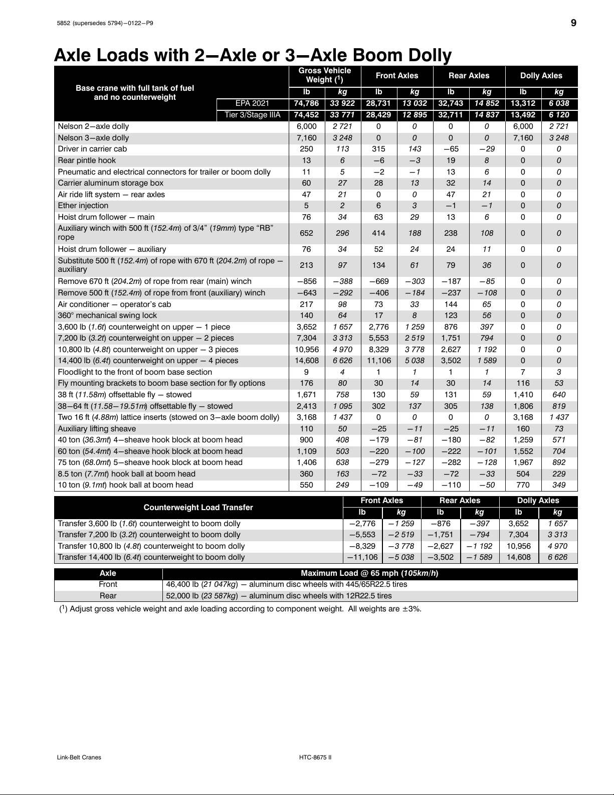
Axle Loads with 2-Axle or 3-Axle Boom Dolly
Base crane with full tank of fuel
and no counterweight
Gross Vehicle
Weight (1)Front Axles Rear Axles Dolly Axles
lb kg lb kg lb kg lb kg
EPA 2021 74,786 33 922 28,731 13 032 32,743 14 852 13,312 6 038
Tier 3/Stage IIIA 74,452 33 771 28,429 12 895 32,711 14 837 13,492 6 120
Nelson 2-axle dolly 6,000 2 721 00006,000 2 721
Nelson 3-axle dolly 7,160 3 248 00007,160 3 248
Driver in carrier cab 250 113 315 143 -65 -29 00
Rear pintle hook 13 6-6 -3 19 800
Pneumatic and electrical connectors for trailer or boom dolly 11 5-2 -1 13 600
Carrier aluminum storage box 60 27 28 13 32 14 00
Air ride lift system - rear axles 47 21 0047 21 00
Ether injection 5263-1 -1 00
Hoist drum follower - main 76 34 63 29 13 600
Auxiliary winch with 500 ft (152.4m) of 3/4” (19mm) type “RB”
rope 652 296 414 188 238 108 00
Hoist drum follower - auxiliary 76 34 52 24 24 11 00
Substitute 500 ft (152.4m) of rope with 670 ft (204.2m) of rope -
auxiliary 213 97 134 61 79 36 00
Remove 670 ft (204.2m) of rope from rear (main) winch -856 -388 -669 -303 -187 -85 00
Remove 500 ft (152.4m) of rope from front (auxiliary) winch -643 -292 -406 -184 -237 -108 00
Air conditioner - operator's cab 217 98 73 33 144 65 00
360° mechanical swing lock 140 64 17 8123 56 00
3,600 lb (1.6t) counterweight on upper - 1 piece 3,652 1 657 2,776 1 259 876 397 00
7,200 lb (3.2t) counterweight on upper - 2 pieces 7,304 3 313 5,553 2 519 1,751 794 00
10,800 lb (4.8t) counterweight on upper - 3 pieces 10,956 4 970 8,329 3 778 2,627 1 192 00
14,400 lb (6.4t) counterweight on upper - 4 pieces 14,608 6 626 11,106 5 038 3,502 1 589 00
Floodlight to the front of boom base section 94111173
Fly mounting brackets to boom base section for fly options 176 80 30 14 30 14 116 53
38 ft (11.58m) offsettable fly - stowed 1,671 758 130 59 131 59 1,410 640
38-64 ft (11.58-19.51m) offsettable fly - stowed 2,413 1 095 302 137 305 138 1,806 819
Two 16 ft (4.88m) lattice inserts (stowed on 3-axle boom dolly) 3,168 1 437 00003,168 1 437
Auxiliary lifting sheave 110 50 -25 -11 -25 -11 160 73
40 ton (36.3mt) 4-sheave hook block at boom head 900 408 -179 -81 -180 -82 1,259 571
60 ton (54.4mt) 4-sheave hook block at boom head 1,109 503 -220 -100 -222 -101 1,552 704
75 ton (68.0mt) 5-sheave hook block at boom head 1,406 638 -279 -127 -282 -128 1,967 892
8.5 ton (7.7mt) hook ball at boom head 360 163 -72 -33 -72 -33 504 229
10 ton (9.1mt) hook ball at boom head 550 249 -109 -49 -110 -50 770 349
Counterweight Load Transfer Front Axles Rear Axles Dolly Axles
lb kg lb kg lb kg
Transfer 3,600 lb (1.6t) counterweight to boom dolly -2,776 -1 259 -876 -397 3,652 1 657
Transfer 7,200 lb (3.2t) counterweight to boom dolly -5,553 -2 519 -1,751 -794 7,304 3 313
Transfer 10,800 lb (4.8t) counterweight to boom dolly -8,329 -3 778 -2,627 -1 192 10,956 4 970
Transfer 14,400 lb (6.4t) counterweight to boom dolly -11,106 -5 038 -3,502 -1 589 14,608 6 626
Axle Maximum Load @ 65 mph (105km/h)
Front 46,400 lb (21 047kg) - aluminum disc wheels with 445/65R22.5 tires
Rear 52,000 lb (23 587kg) - aluminum disc wheels with 12R22.5 tires
(
1
) Adjust gross vehicle weight and axle loading according to component weight. All weights are ±3%.
Courtesy of CraneMarket.com

10 5852 (supersedes 5794)-0122-P9
HTC‐8675 II Link‐Belt Cranes
General Dimensions
EPA 2021
R
Not To Scale
Turning Radius English Metric
Wall to wall over carrier 48' 4” 14.7m
Wall to wall over boom 52' 2” 15.9m
Wall to wall over boom attachment 53' 1” 16.2m
Curb to curb 44' 1” 13.4m
Centerline of tire 43' 4” 13.2m
Tail Swing English Metric
With counterweight 13' 9” 4.2m
Overall Width English Metric
With up to 14,400 lb (6.4t) counterweight 8' 6” 2.6m
With 18,400 lb (8.2t) counterweight 10' 4” 3.1m
48' 5.6”
(14.77m)
40' 11.5”
(12.48m)7' 0”
(2.13m)
11' 5”
(3.48m)
20.31”
(0.52m)
6' 2.8”
(1.90m)
8' 1”
(2.46m)
4.48”
(0.11m)
4' 2”
(1.27m)
14' 8”
(4.47m)
16°
8' 0.6”
(2.45m)
5' 0”
(1.52m)
5' 9”
(1.75m)2' 10”
(0.86m)
17°
10.90” (0.28m)
Ground Clearance
9' 6”
(2.90m)
11' 0”
(3.35m)
23.09”
(0.59m)
C
LOf Rotation
14.36”
(0.36m)
7' 8.6” (2.35m)
Fully Retracted
9' 8.4” (2.96m)
Fully Retracted
14' 7” (4.45m)
Intermediate Extended
16' 6.8” (5.05m)
Intermediate Extended
24' 0” (7.32m)
Fully Extended
25' 11.8” (7.92m)
Fully Extended
Ground Level
With Crane On
Outriggers
8.48”
(0.22m)
14.37”
(0.36m)
22.85”
(0.58m)
8' 6”
(2.59m)
11' 1.1”
(3.38m)
Courtesy of CraneMarket.com

11
5852 (supersedes 5794)-0122-P9
HTC‐8675 IILink‐Belt Cranes
General Dimensions
Tier 3 / Stage IIIA
N3P0342
R
Not To Scale
Turning Radius English Metric
Wall to wall over carrier 48' 4” 14.7m
Wall to wall over boom 52' 2” 15.9m
Wall to wall over boom attachment 53' 1” 16.2m
Curb to curb 44' 1” 13.4m
Centerline of tire 43' 4” 13.2m
Tail Swing English Metric
With counterweight 13' 9” 4.2m
Overall Width English Metric
With up to 14,400 lb (6.4t) counterweight 8' 6” 2.6m
With 18,400 lb (8.2t) counterweight 10' 4” 3.1m
48' 5.6”
(14.77m)
40' 11.5”
(12.48m)7' 0”
(2.13m)
11' 5”
(3.48m)
20.31”
(0.52m)
6' 2.8”
(1.90m)
8' 1”
(2.46m)
4.48”
(0.11m)
4' 2”
(1.27m)
14' 8”
(4.47m)
16°
8' 0.6”
(2.45m)
5' 0”
(1.52m)
5' 9”
(1.75m)2' 10”
(0.86m)
17°
10.90” (0.28m)
Ground Clearance
9' 6”
(2.90m)
11' 0”
(3.35m)
23.09”
(0.59m)
C
LOf Rotation
14.36”
(0.36m)
7' 8.6” (2.35m)
Fully Retracted
9' 8.4” (2.96m)
Fully Retracted
14' 7” (4.45m)
Intermediate Extended
16' 6.8” (5.05m)
Intermediate Extended
24' 0” (7.32m)
Fully Extended
25' 11.8” (7.92m)
Fully Extended
Ground Level
With Crane On
Outriggers
8.48”
(0.22m)
14.37”
(0.36m)
22.85”
(0.58m)
8' 6”
(2.59m)
11' 1.1”
(3.38m)
Courtesy of CraneMarket.com

12 5852 (supersedes 5794)-0122-P9
HTC‐8675 II Link‐Belt Cranes
Working Range Diagram
180
(54.9)
190
(57.9)
170
(51.8)
160
(48.8)
150
(45.7)
140
(42.7)
130
(39.6)
120
(36.6)
110
(33.5)
100
(30.5)
90
(27.4)
80
(24.4)
70
(21.3)
60
(18.3)
50
(15.2)
40
(12.2)
30
(9.1)
20
(6.1)
10
(3.0)
0
200
(61.0)
210
(64.0)
220
(67.1)
230
(70.1)
240
(73.2)
20
(6.1)
30
(9.1)
40
(12.2)
50
(15.2)
60
(18.3)
70
(21.3)
80
(24.4)
90
(27.4)
100
(30.5)
110
(33.5)
120
(36.6)
130
(39.6)
140
(42.7)
150
(45.7)
160
(48.8)
170
(51.8)
180
(54.9)
190
(57.9)
200
(61.0)
210
(64.0)
220
(67.1) C
L
Rotation
Of
Operating Radius From Axis Of Rotation In Feet (Meters)
Height In Feet (Meters) Above Ground
10’
(3.0m)
9’ 1”
(2.8m)
80° Max
Boom Angle
41' (12.5m)
50' (15.2m)
60' (18.3m)
70' (21.3m)
80' (24.4m)
90' (27.4m)
100' (30.5m)
110' (33.5m)
120' (36.6m)
127' (38.71m)
127' + 16'
(38.71m + 4.88m)
Boom Length Boom + Fly Length
20°
30°
40°
50°
60° 70°
10°
15° Offset
45_
Offset
2° Offset
30_
Offset
47' (14.3m)
61.3' (18.7m)
76' (23.2m)
98.7' (30.1m)
113.1' (34.5m)
98.7' + 38'
(30.1m + 11.58m)
127' + 38'
(38.71m + 11.58m)
98.7' + 64'
(30.1m + 19.51m)
127' + 64'
(38.71m + 19.51m)
127' + 80'
(38.71m + 24.38m)
127' + 96'
(38.71m + 29.26m)
Courtesy of CraneMarket.com

13
5852 (supersedes 5794)-0122-P9
HTC‐8675 IILink‐Belt Cranes
Boom Extend Modes
Boom Length Section Length
Extend
41' (12.5m)
127' (38.71m)
BaseT3 T2 T1
Base
ft mT3 T2 T1
50 15.2 32%
60 18.3 68%
70 21.3 100% 4%
80 24.4 100% 39%
90 27.4 100% 74%
100 30.5 100% 100% 8%
110 33.5 100% 100% 42%
120 36.6 100% 100% 76%
127 38.71 100% 100% 100%
Boom Length Section Length
BaseT3 T2 T1
Extend
Base
41' (12.5m)
113.1' (34.47m)
ft mT3 T2 T1
50 15.2 32%
60 18.3 50% 18%
70 21.3 50% 53%
80 24.4 50% 87%
90 27.4 50% 100% 22%
100 30.5 50% 100% 56%
113.1 34.5 50% 100% 100%
Boom Length Section Length
BaseT3 T2 T1
Extend
Base
41' (12.5m)
98.7' (30.1m)
ft mT3 T2 T1
50 15.2 32%
60 18.3 50% 18%
70 21.3 50% 50% 3%
80 24.4 50% 50% 37%
90 27.4 50% 50% 71%
98.7 30.1 50% 50% 100%
Boom Length Section Length
BaseT2 T1
Extend
Base
41' (12.50m)
76.0' (23.16m)
T3
ft mT3 T2 T1
47 14.3 22%
61.3 18.7 22% 50%
76 23.2 22% 50% 50%
Courtesy of CraneMarket.com

14 5852 (supersedes 5794)-0122-P9
HTC‐8675 II Link‐Belt Cranes
Main Boom Lift Capacity Charts - Imperial B30.5 - Standard
0 lb Counterweight - Fully Extended Outriggers - 360° Rotation
(All Capacities Are Listed In Pounds)
Radius
(ft)
Boom Length (ft) Radius
(ft)
41 50 60 70 80 90 100 110 120 127
10 124,900 110,700 106,900 74,400 10
12 102,600 103,900 104,800 81,000 62,800 12
15 79,900 81,300 82,500 77,400 62,800 61,400 15
20 57,100 59,100 59,800 60,700 60,400 57,100 47,900 29,100 20
25 43,300 45,300 46,400 46,900 46,700 46,500 42,500 32,800 25,500 22,600 25
30 30,600 33,100 34,600 34,800 35,100 34,300 34,800 32,100 25,500 22,600 30
35 24,600 26,100 26,300 27,400 27,700 26,400 26,600 25,500 22,600 35
40 18,600 20,200 21,100 21,400 21,600 21,700 21,400 21,100 20,900 40
45 16,000 16,900 17,200 17,400 17,400 17,100 16,900 16,700 45
50 12,800 13,800 14,100 14,200 14,300 14,000 13,700 13,600 50
55 11,400 11,700 11,900 12,000 11,700 11,500 11,300 55
60 9,500 9,800 10,000 10,100 9,800 9,600 9,500 60
65 6,400 8,300 8,500 8,500 8,300 8,000 7,900 65
70 6,900 7,200 7,200 7,000 6,800 6,600 70
75 6,100 6,200 5,900 5,700 5,600 75
80 5,100 5,200 5,000 4,800 4,700 80
85 4,400 4,200 4,000 3,900 85
90 3,700 3,500 3,300 3,200 90
95 2,900 2,700 2,600 95
100 2,300 2,200 2,100 100
105 1,000 1,700 1,600 105
110 1,300 1,200 110
115 800 115
This information is not for crane operation. Operator must refer to the in-cab information for crane operation. Rated lifting capaci
ties shown on fully extended outriggers do not exceed 85% of the tipping loads and on tires do not exceed 75% of the tipping loads.
Courtesy of CraneMarket.com

15
5852 (supersedes 5794)-0122-P9
HTC‐8675 IILink‐Belt Cranes
0 lb Counterweight - On Tires - Stationary - Boom Centered Over Rear
(All Capacities Are Listed In Pounds)
Radius
(ft)
Boom Length (ft) Radius
(ft)
41 50 60 70 80 90
10 33,800 10
12 30,600 31,500 26,500 12
15 23,500 25,400 26,500 20,300 15
20 14,100 15,900 17,200 17,900 16,600 20
25 8,900 10,600 11,800 12,700 12,800 13,000 25
30 5,500 7,200 8,400 9,200 9,500 9,700 30
35 4,800 6,000 6,800 7,100 7,300 35
40 3,100 4,300 5,000 5,300 5,500 40
45 2,900 3,700 3,900 4,100 45
50 1,900 2,600 2,900 3,100 50
55 1,700 2,000 2,200 55
60 1,000 1,300 1,500 60
0 lb Counterweight - On Tires - Pick & Carry (1 mph) - Boom Centered Over Rear
(All Capacities Are Listed In Pounds)
Radius
(ft)
Boom Length (ft) Radius
(ft)
41 50 60 70 80 90
10 23,900 10
12 21,300 22,200 22,900 12
15 18,100 19,100 19,900 20,300 15
20 14,000 15,100 15,900 16,400 16,600 20
25 8,900 10,600 11,800 12,700 12,800 13,000 25
30 5,500 7,200 8,400 9,200 9,500 9,700 30
35 4,800 6,000 6,800 7,100 7,300 35
40 3,100 4,300 5,000 5,300 5,500 40
45 2,900 3,700 3,900 4,100 45
50 1,900 2,600 2,900 3,100 50
55 1,700 2,000 2,200 55
60 1,000 1,300 1,500 60
This information is not for crane operation. Operator must refer to the in-cab information for crane operation. Rated lifting capaci
ties shown on fully extended outriggers do not exceed 85% of the tipping loads and on tires do not exceed 75% of the tipping loads.
Courtesy of CraneMarket.com
Table of contents
Other Link-Belt Construction Equipment manuals


Popular Construction Equipment manuals by other brands

Fayat Group
Fayat Group BOMAG BF 700 C-2 Service manual

Epiroc
Epiroc Secoroc COP 54 Operator's instructions/Spare parts list

stellar labs
stellar labs EC6000 owner's manual

Graco
Graco 231-133 B Instructions-parts list

Auto Crane
Auto Crane NEXSTAR EHC-6 owner's manual

Zoomlion
Zoomlion RT60 Maintenance and service manual


