GP HBM-NOBAS BG 160TA-4 Technical specifications
B A U M A S C H I N E N
Maintenance instructions
BG 160TA-4
Motor Grader
Motorgrader
Niveleuse
englisch
01/2007

Motor Grader
Motorgrader
Niveleuse
BG 160TA-4
Maintenance instructions
Wartungsanleitung
Instructions d’entretien
01/2007 HBM/NOBAS construction machine

Maintenance instructions BG
Table of Contents
Preface 1
Safety regulations 2
Running-in period 3
Drive engine 4
Daily Maintenance Procedures 4.1
Daily Maintenance Procedures - Overview 4.1.1
Crankcase Breather Tube 4.1.2
Fuel-Water Separator 4.1.3
Lubricating Oil Level 4.1.4
Coolant Level 4.1.5
Drive Belts 4.1.6
Maintenance Procedures at 250 hours or 3 months 4.2
Air Cleaner Restriction 4.2.1
Charge-Air Cooler 4.2.2
Charge-Air Piping 4.2.3
Radiator Hoses 4.2.4
Air Intake Piping 4.2.5
Fan, Cooling 4.2.6
Maintenance Procedures at 500 hours or 6 months 4.3
Cooling System 4.3.1
Fuel Filter (Spin-On Type) 4.3.2
Lubricating Oil and Filters 4.3.3
Maintenance Procedures at 1000 hours or 1 year 4.4
Cooling Fan Belt Tensioner 4.4.1
Fan Hub, Belt Driven 4.4.2
Maintenance Procedures at 2000 hours or 2 years 4.5
Cooling System 4.5.1
Cooling system 5
Checking the coolant level 5.1
External cleaning of the cooler 5.2

Maintenance instructions BG
Table of Contents
Air filter system 6
Air filter 6.1
Replacement, removal and insertion of the filter insert 6.1.1
Blowing-off the filter insert 6.1.2
Checking the filter insert 6.1.3
Replacement of safety cartridge 6.1.4
Ergopower gear 7
Gear type 6 WG 160 7.1
Battery 8
Rear axle 9
Checking the oil levels 9.1
Exchange of oil at the rear axle 9.2
NO SPIN differential 9.3
Drive shafts 9.4
Front axle 10
Braking system 11
Parking brake 11.1
Bleeding the brake 11.2
Servicing the wheel brake 11.3
Parking brake emergency release 11.4
Moldboard assembly 12
Lubricating the moldboard assembly 12.1
Greasing the moldboard assembly 12.2
Readjustment the blade guide 12.3
Readjustment the circle 12.4
Circle drive 12.5
Hydraulic working system 13
Checking oil level 13.1
Refilling with oil 13.2
Changing the oil 13.3

Maintenance instructions BG
Table of Contents
Replacement of the hydraulic filter 13.4
Replacement of the filter cartridge of the backflow filter 13.4.1
High-pressure filter cleaning 13.4.2
Replace the filter cartridge of the high-pressure filter 13.4.2.1
Articulated frame joint and articulated steering cylinder 14
Lubrication of the grading plate 15
Rear ripper 16
Changing the tyres 17
Tyre Ballast (Option) 17.1
How to use the combined „WASSER-BOY“ water filler and drainage unit 17.1.1
Electrical system 18
Electrical system on the machine 18.1
Electrical symbols 18.2
Lubricants, fuels, filling quantities 19
Lubricants 20
Diesel fuels 21
Long-term coolants 22
Winter operation 23
Shutting the machine down for a longer period 24
Maintenance and inspection plan 25

Maintenance instructions 1
1
1 Preface
Proper operation and care are important prerequisites for maintaining the serviceability of the building machine.
These maintenance instructions should always be within the machine operator’s reach.
Please read the maintenance instructions and safety rules carefully and follow them strictly. Carry out the inspections,
checks and maintenance jobs at the specified intervals. Any guarantee claims will only be recognized if all the inspections,
checks and maintenance work have been carried out properly and at the specified intervals before the date of dam-
age/defect.
Be aware that regular maintenance and inspections can prevent unexpected and unnecessary downtimes.
Should troubles occur with the machine or equipment, report to the persons responsible for maintenance and repair. If a
trouble may lead to consequential damage, put the machine out of operation and remedy the trouble.
Jobs marked with this symbol in the maintenance instructions should only be done by our agents’
expert staff.
At the printing date of this manual, the building machine described herein corresponded to the state of the art. In the inter-
est of further development, we reserve the right to make changes to our products at any time without simultaneously updat-
ing these maintenance instructions. For this reason, we recognize no claims arising from technical data, descriptions and
figures which deviate from those of the machine.
Note: The test, measuring, and diagnostic equipment mentioned in the maintenance instructions is not included in the
machine's scope of supply. Please call your authorised service representative.

Maintenance instructions 2
2
2 Safety regulations
As to the inspections, checks and maintenance of the building machine, the safety regulations of the country in which the
machine is used and those of the trade association concerned are applicable.
The regulations specified in European standards EN 474-1 and EN 474-8 are applicable to this.
In the Federal Republic of Germany, the requirements are applicable in accordance with the material content of the "Op-
eration" section in the accident prevention regulations for "earth-moving machinery" (VBG 40).
Control equipment may only be operated from the driver’s seat or operator’s stand.
Only the steps and platforms intended for climbing and walking may be used for the purpose. Their walksafe condition
must be maintained.
Protections covering moving machine parts may only be opened after the drive has been stopped and secured against
unintentional starting.
After the maintenance or repair work, all protections must be properly closed or replaced.
Such protections are, for example: engine covers, doors, safeguards, protective gratings, panels.
The breakdown coupling may only be used for towing vehicles which are not in working order. Towing a trailer with this
coupling in road traffic is not permissible.
Keep out of the machine’s danger zone!
When the engine is running, keep also out of the frame articulation zone!
Do not stand under the lifted and unsecured grading equipment!
Before the execution of any welding work at the grader, make sure that the dynamo, the micro-
processor and the battery are completely disconnected!
See also section 1.2 of the operation instructions for this machine; it is considered part of these
maintenance instructions.
Original HBM parts are especially designed for HBM machines.
Please note that parts and accessories not supplied by us are not tested and approved by us. The use of such products
may affect specific design characteristics of your machine negatively and, consequentially, have an adverse effect on the
active and/or passive safety. The machine manufacturer is not liable for damage caused by the use of parts and accesso-
ries which are not original parts or accessories.

Maintenance instructions 3
3
3 Running-in period
It is particularly important to carry out the inspections and maintenance work in line with the following schedule (after the
first 100 hours of operation):
Engine Change oil and oil filter cartridge.
Check the coolant level.
Inspect the V-belt.
Drain the water from the fuel prefilter.
Clean the air cleaner.
Ergopower-gear Change oil filter cartridge
Hydraulic system Change the oil filter on contamination
Front and rear axles Retighten the wheel nuts.
Fittings Check for leakage, retighten.
Gears and wheel hubs Check oil levels, refill if required
Important!
Check the tightening torques of the wheel nuts in the following way:
Before initial operation, 50 hours of operation after each wheel mounting, and during each inspection.
Wheel nut tightening torque: 550 Nm (746 lbft).

Maintenance instructions 4
4
4.1
4 Drive engine
General Information
At each scheduled maintenance interval, perform all previous maintenance checks that are due for scheduled mainte-
nance.
Maintenance Schedule
Daily or Refueling - Maintenance Check (3)
•Crankcase Breather Tube – Inspect
•Fuel-Water Separator – Drain
•Engine oil level - Check
•Coolant Level – Check/Correct
•Drive Belts – Check/Correct
Section 4.1
Every 250 hours or 3 months - Maintenance Check (3)
•Air Cleaner Restriction – Check/Correct
•Charge Air Cooler – Check/Correct
•Charge Air Piping – Check/Correct
•Radiator Hoses – Check
•Air admission line - Check
•Cooling Fan – Check
Section 4.2
Every 500 hours or 6 month - Maintenance Check (1, 2, 3)
•Engine Coolant – Antifreeze Check
•Fuel Filter, Spin-on-Type – Replace
•Lubricating Oil and Filters – Change
Section 4.3
Every 1000 hours or 1 year - Maintenance Check (3)
•Cooling Fan Belt Tensioner – Check/Correct
•Fan Hub, Belt-Driven – Check/Correct
Section 4.4
Every 2000 hours, or 2 years - Maintenance Check (2, 3)
•Cooling System – Drain, Flush, and Fill Section 4.5
(1) The lubricating oil and lubricating oil filter interval can be adjusted based on application, fuel consumption, gross
vehicle weight, and idle time. See the Oil Drain Intervals in this section.
(2) Antifreeze check interval is every oil change or 500 hours or 6 months, whichever occurs first. The operator must use
a heavy-duty year-round antifreeze that meets the chemical composition of GM6038M. The antifreeze change interval
is 2 years or 2000 hours whichever occurs first. Antifreeze is essential for freeze, overheat, and corrosion protection.
(3) Follow the manufacturer’s recommended maintenance procedures for the starter, alternator, generator, batteries,
electrical components, exhaust brake, charge air cooler, radiator, air compressor, air cleaner, freon compressor, and
fan clutch. Refer to Procedure 203-001 (Component Manufacturers) in Section M.
Oil Drain Intervals
American Petroleum Insti-
tute Classification (API) European Classification
(ACEA) Engine Rating is 260Hp [194] or less
API CH-4/SJ ACEA E-5 500 hours or 6 months
Maintenance instructions 4
4.1
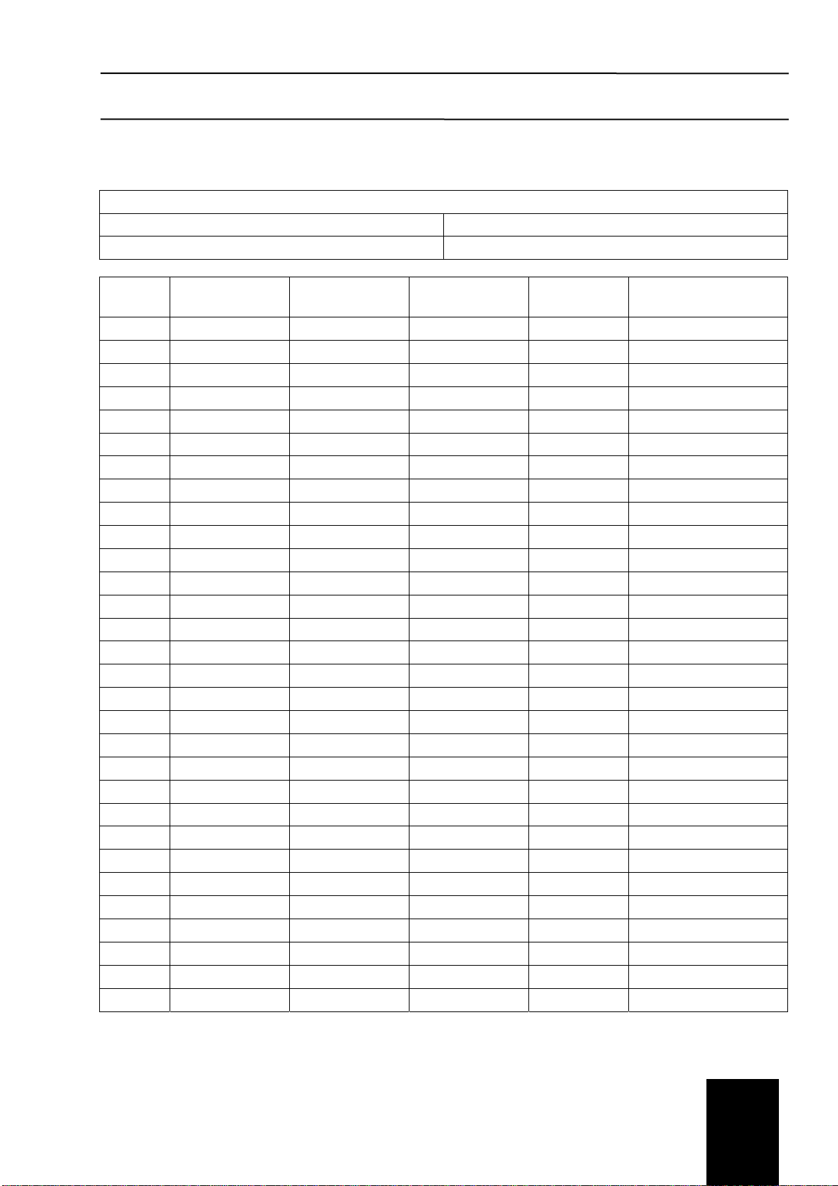
Maintenance Record
Maintenance Record
Engine Serial No.: Engine Model:
Owner’s Name: Equipment Name/Number:
Date km [Miles], hours
or Time Interval Actual km [Miles]
or hours Maintenance
Check Performed Check Per-
formed By Comments
Maintenance instructions 4
4.1
4.1 Daily Maintenance Procedures
4.1.1 Daily Maintenance Procedures - Overview
General Information
Preventative maintenance begins with day-to-day awareness of the engine
and its system. Before starting the engine, check the oil and coolant levels.
Look for:
•Leaks
•Loose or damaged parts
•Worn or damaged belts
•Any change in engine appearance.
•Odor of fuel
Engine Operation Report
The engine must be maintained in top mechanical condition if the operator
is to get optimum satisfaction from its use. The maintenance department
needs daily running reports from the operator to make necessary adjust-
ments in the time allocated. The daily running reports also helps to make
provisions for more extensive maintenance work as the reports indicate the
necessity.
Report to the maintenance department any of the following conditions:
•Low lubricating oil pressure
•Low power
•Power increases or engine surge
•Erratic or no accelerator control or response
•Any warning lights flashing or staying on
•Abnormal water or oil temperature
•Unusual engine noise
•Excessive smoke
•Excessive use of coolant, fuel, or lubricating oil
•Any fuel, coolant, or lubricating oil leaks
•Loose or damaged parts
•Worn or damaged belts
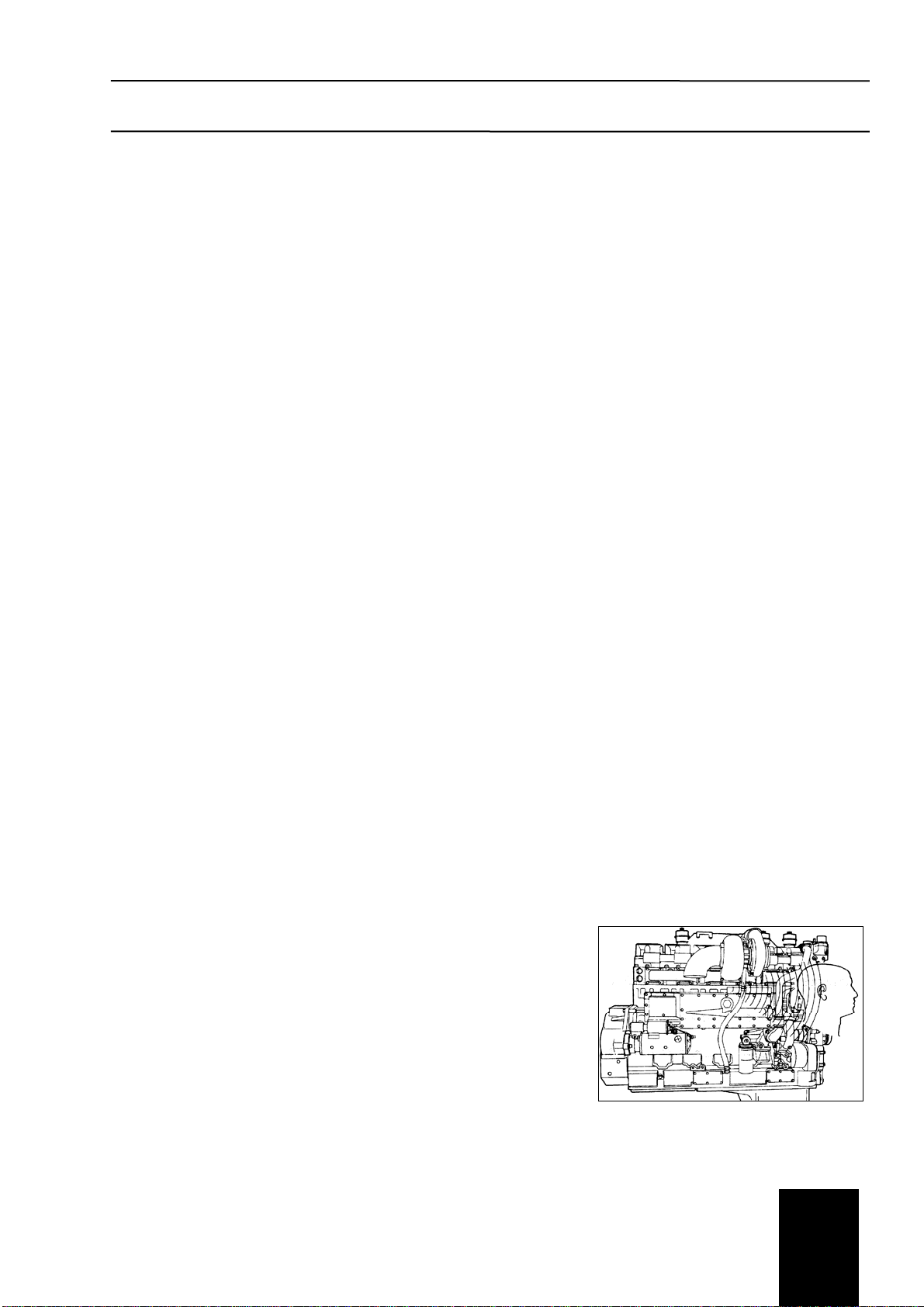
Unusual Engine Noise
Fig. 4.1.1/1
During daily maintenance checks, listen for any unusual engine noise that
can indicate that service is required.
Fig. 4.1.1/1
Maintenance instructions 4
4.1
4 4.1.2Crankcase Breather Tube
Fig. 4.1.2/1
Maintenance Check
Inspect the breather tube for sludge, debris, or ice in the tube.
The tube must be free.
Inspect the tube more frequently in icy conditions.
The line must be laid freely, and must not be kinked.
4.1.3 Fuel-Water Separator
Drain
Warning!
Drain the water-fuel separator into a container
and dispose of in accordance with local envi-
ronmental regulations.
Drain the water and sediment from the separator daily.
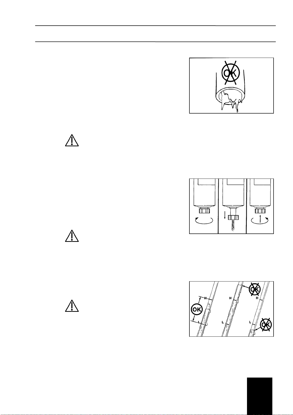
Spin-on Type
Fig. 4.1.3/1
Shut off the engine.
Use your hand to open the drain valve. Turn the valve counterclockwise
approximately 3½ turns until the valve drops down 25,4mm [1in] and drain-
ing occurs.
Drain fluid from the filter bottom part until you see clear fuel flowing out.
Caution!
When closing the drain valve, do not overtighten
the valve. Overtightening can damage the
threads.
To close the valve, lift the valve and turn clockwise until it is hand-tight.
4.1.4 Lubricating Oil Level
Fig. 4.1.4/1
Maintenance Check
Caution!
Never operate the engine with oil level below the
L (low) mark or above the H (high) mark. Poor
engine performance or engine damage can
occur.
The engine must be level when checking the oil level to make sure the
measurement is correct.
Shut off the engine for an accurate reading.
Wait at least 15 minutes after shutting off the engine to check the oil level.
This allows time for the oil to drain into the oil pan.
For further recommendations on lubricating oil, see the maintenance speci-
fications (chapter 20).
Fig. 4.1.2/1
Fig. 4.1.3/1
Fig. 4.1.4/1
Maintenance instructions 4
4.1
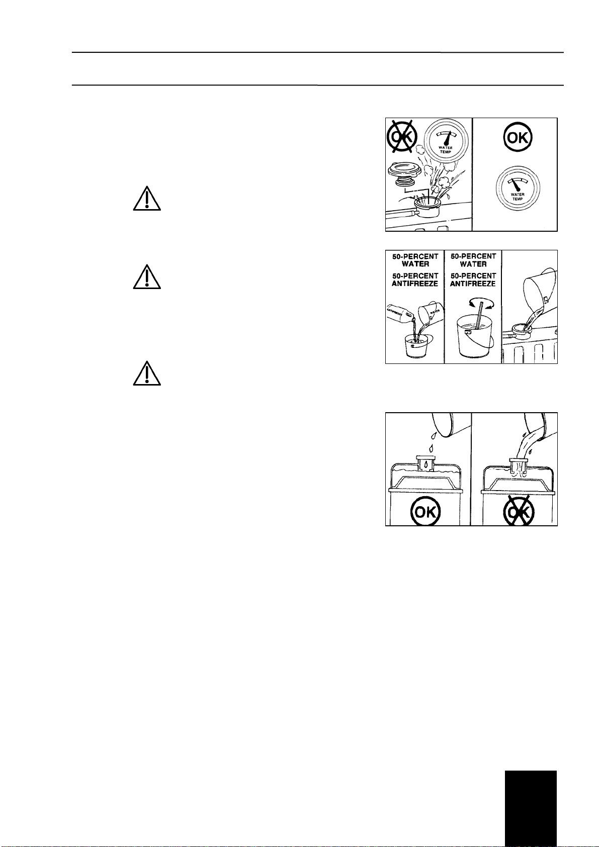
4.1.5 Coolant Level
Fig. 4.1.5/1 to 4.1.5/3
Maintenance Check
Warning!
Do not remove a pressure cap from a hot en-
gine. Wait until the coolant temperature is below
50°C (120°F) before removing the pressure cap.
Heated coolant spray or steam can cause per-
sonal injury.
Caution!
Never use a sealing additive to stop leaks in the
cooling system. This can result in cooling system
plugging and inadequate coolant flow, causing
the engine to overheat.
The coolant level must be checked daily.
Caution!
Do not add cold coolant to a hot engine. Engine
castings can be damaged. Allow the engine to
cool to below 50°C (120°F) before adding cool-
ant.
Make up coolant added to the engine must be mixed with the correct pro-
portions of antifreeze, supplemental coolant additive, and water to avoid
engine damage.
Coolant recommendations and specification details on correct mixing of
coolant can be found in Maintenance Specifications (Section 22).
Fill the cooling system with coolant to the bottom of the fill neck in the radia-
tor fill or expansion tank.
Fig. 4.1.5/1
Fig. 4.1.5/2
Fig. 4.1.5/3

Maintenance instructions 4
4.1
4.1.6 Drive Belts
Fig. 4.1.6/1
Maintenance Check
Cogged Belt
Inspect the belts daily. Replace the belts if they are cracked, frayed, or
have chunks of material missing. Small cracks are acceptable.
Adjust the belts that have a glazed or shiny surface, which indicates belt
slippage. Correctly installed and tensioned belts will show even pulley and
belt wear.
Belt damage can be caused by:
•Incorrect tension
•Incorrect size or length
•Pulley misalignment
•Incorrect installation
•Severe operating environment
•Oil or grease on the belts
Fig. 4.1.6/1
Maintenance instructions 4
4.2
4.2 Maintenance Procedures at 250 hours or 3 months
4.2.1 Air Cleaner Restriction
Maintenance Check
Refer to item 6.1of the maintenance instructions.
Caution!
Never operate the engine without an air cleaner.
Intake air must be filtered to prevent dirt and
debris from entering the engine and causing
premature wear.
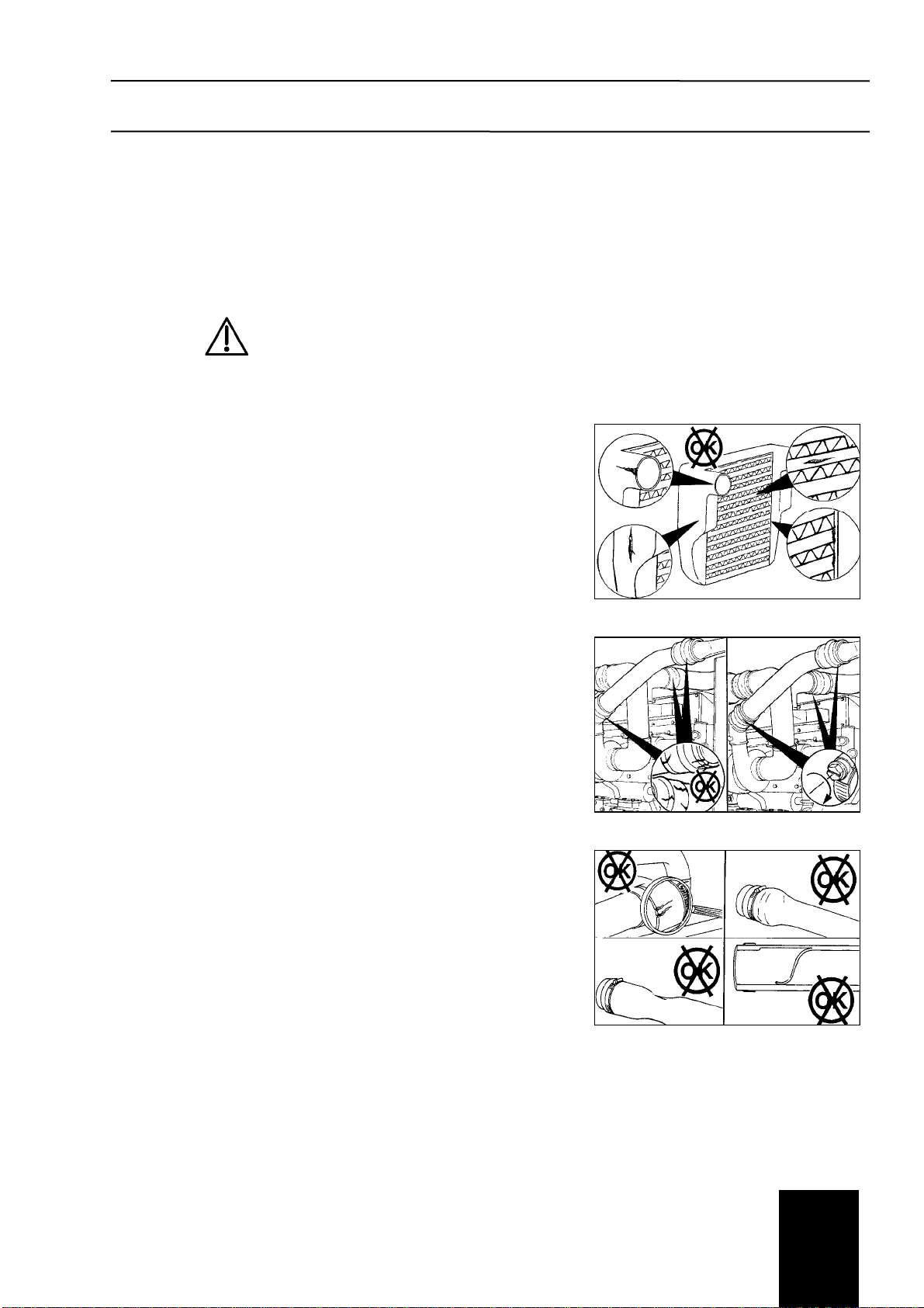
4.2.2 Charge-Air Cooler
Fig. 4.2.2/1
Maintenance Check
Inspect the charge-air cooler (CAC) for dirt and debris blocking the fins.
Check for cracks, holes, or other damage. If damage is found, refer to the
vehicle, vessel, or equipment manufacturer.
4.2.3 Charge-Air Piping
Fig. 4.2.3/1
Maintenance Check
Inspect the charge-air piping and hoses for leaks, holes, cracks, or loose
connections. Tighten the hose clamps if necessary.
4.2.4 Radiator Hoses
Fig. 4.2.4/1
Maintenance Check
Check all hoses for cracks, cuts, or collapsing.
Note: The silicone engine coolant hose will exhibit swelling due to the
elasticity of the hose.
Fig. 4.2.2/1
Fig. 4.2.3/1
Fig. 4.2.4/1
Maintenance instructions 4
4.2
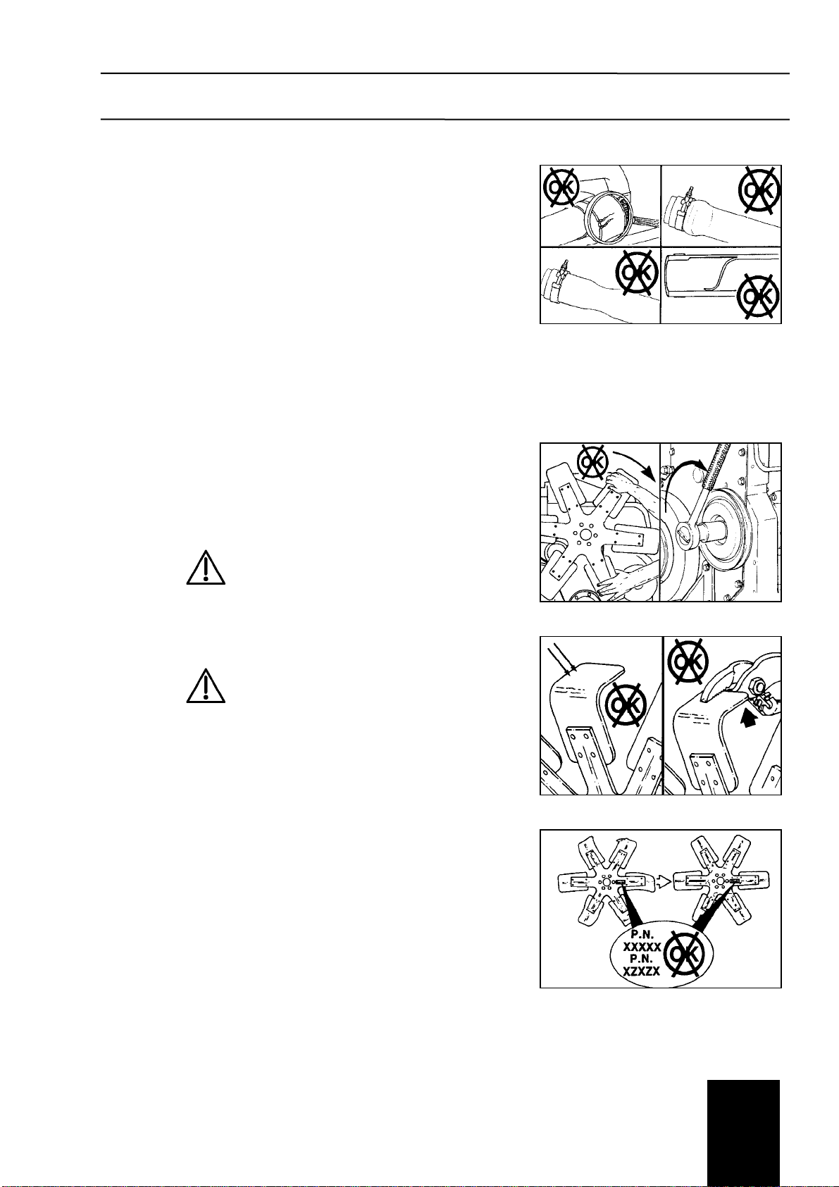
4.2.5 Air Intake Piping
Fig. 4.2.5/1
Maintenance Check
Visually inspect the intake piping daily for wear points and damage to pip-
ing, loose clamps, or punctures that can damage the engine.
Replace damaged pipes, and tighten loose clamps, as necessary, to pre-
vent the air system from leaking.
Torque Value: 8 Nm [72 in-lb]
Check for corrosion under the clamps and hoses of the intake system pip-
ing. Corrosion can allow corrosive products and dirt to enter the intake
system. Disassemble and clean, as required.
4.2.6 Fan, Cooling
Fig. 4.2.6/1 to 4.2.6/3
Inspect for Reuse
Warning!
Do not rotate the engine by pulling or prying on
the fan. The fan blade(s) can be damaged and
cause the fan to fail and cause personal injury or
property damage. Use the accessory drive shaft
or the crankshaft barring tool to rotate the crank-
shaft.
Warning!
Do not straighten a bent fan blade or continue to
use a damaged fan. A bent or damaged fan
blade can fail during operation and cause per-
sonal injury or property damage.
Replace a damaged fan by a new fan with the same part number. Any other
change or modification to the fan requires a prior authorization by the
manufacturer to be covered by warranty.
The tightening torque for the hexagon bolt is 40 Nm.
Fig. 4.2.5/1
Fig. 4.2.6/1
Fig. 4.2.6/2
Fig. 4.2.6/3

Maintenance instructions 4
4.3
4.3 Maintenance Procedures at 500 hours or 6 months
4.3.1 Cooling System
Maintenance Check - coolant
Refer to item 22 of the maintenance instructions.
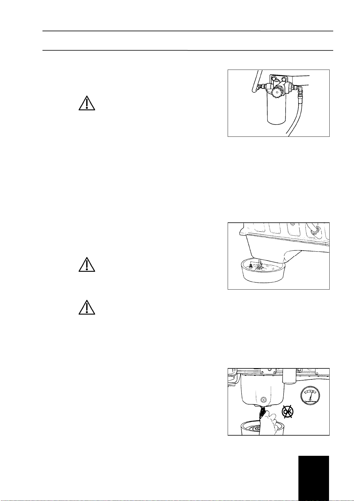
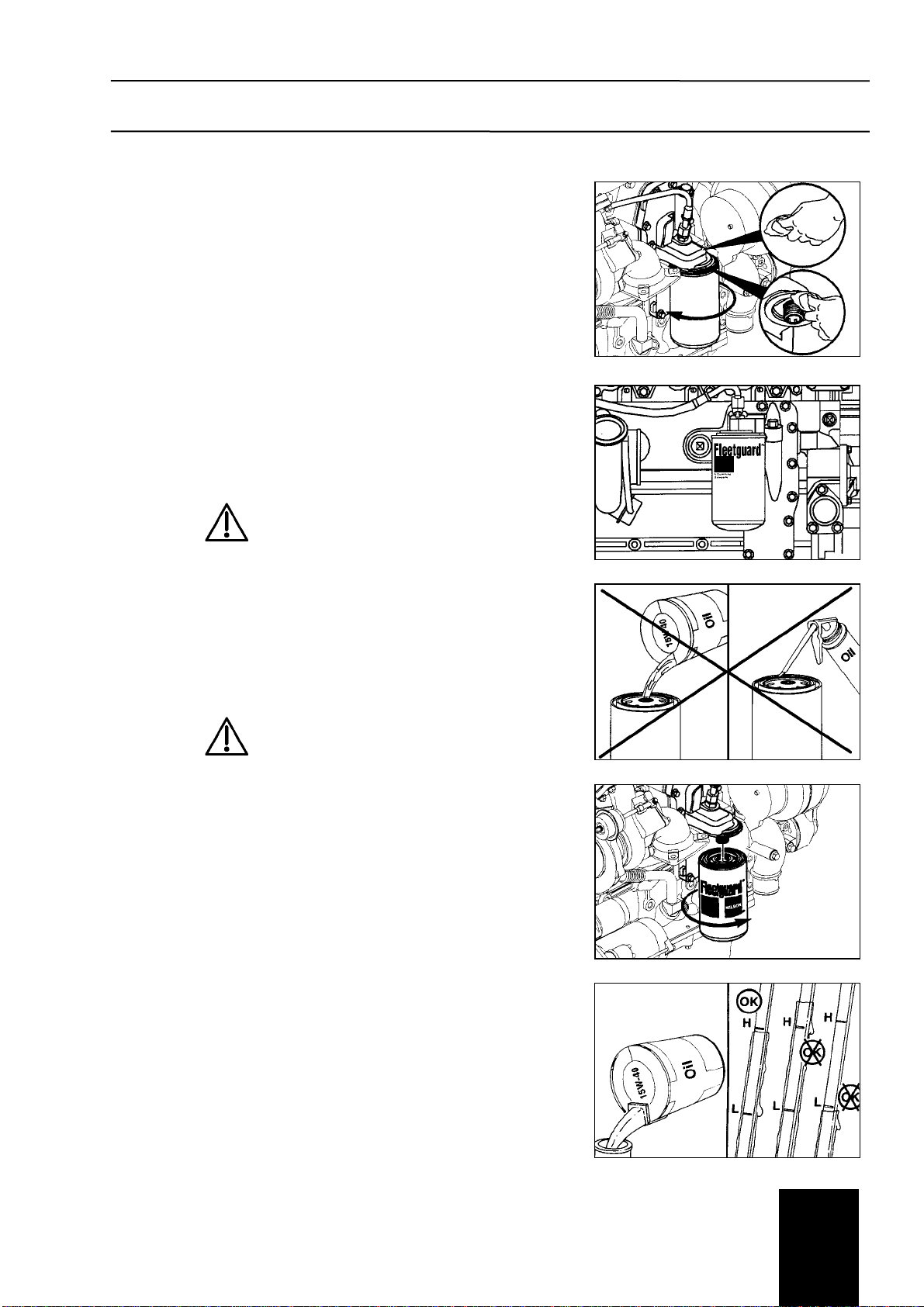
4.3.2 Fuel Filter (Spin-On Type)
Remove
Fig. 4.3.2/1
Remove the spin-on fuel filter with fuel filter wrench.
Install
Fig. 4.3.2/2
Note: Do not prefill the fuel filter.
Caution!
Do not pre-fill the on-engine fuel filter with fuel.
The system must be primed after the fuel filter is
installed. Pre-filling the fuel filter can result in
debris entering the fuel system and damaging
fuel system components.
Lubricate the o-ring seal with clean lubricating oil.
Caution!
Mechanical overtightening will distort the
threads, filter element seal, or filter can.
Use the correct fuel filter (see spare parts catalogue, page 25.001).
Install the filter on the filter head. Tighten the filter until the gasket contacts
the filter head surface.
After making contact, tighten the fuel filter by another ¾ turn.
Torque Value: 34 Nm [25 ft-lb]
Prime fuel system after fuel filter installation.
Fig. 4.3.2/1
Fig. 4.3.2/2
Maintenance instructions 4
4.3
Prime
Fig. 4.3.2/3
Warning!
The fuel pump high-pressure fuel lines and fuel
rail contain very high-pressure fuel. Never
loosen any fittings while the engine is running.
Personal injury and property damage can result.
Use the installed filling device to fill the engine. Typically, a priming pump is
installed at or near the prefilter. Use lever movements (hand pump) to fill
the low pressure system.
Note: It is not necessary to vent air from the high pressure system before
starting the engine.
Note: It is not necessary to pre-fill the on-engine fuel filter.
Operate the engine and check for leaks.
4.3.3 Lubricating Oil and Filters
Drain
Fig. 4.3.3/1 and 4.3.3/2
Warning!
Some state and federal agencies have deter-
mined that used engine oil can be carcinogenic
and cause reproductive toxicity. Avoid inhalation
of vapors, ingestion, and prolonged contact with
used engine oil. If not reused, dispose of in
accordance with local environmental regulations.
Warning!
To reduce the possibility of personal injury, avoid
direct contact of hot oil with your skin.
Change the lubricating oil and filter(s) at the specified oil change interval.
See the Maintenance Schedule to find the correct change interval for your
application.
Note: The engine requires a tank with a capacity of not less than 18 litres of
lubricating oil.
Operate the engine until the water temperature reaches 60°C (140°F).
Shut off the engine.
Remove the oil drain plug. Drain the oil immediately to be sure all the oil
and suspended contaminants are removed from the engine.
Fig. 4.3.2/3
Fig. 4.3.3/1
Fig. 4.3.3/2
Maintenance instructions 4
4.3
Remove
Fig. 4.3.3/3
Clean the area around the lubricating oil filter head.
Use the oil filter wrench to remove the filter.
Clean the gasket surface of the filter head.
Note: The o-ring can stick on the filter head. Make sure it is removed be-
fore installing the new filter.
Install
Fig. 4.3.3/4 to 4.3.3/6
Use the correct oil filter (refer to page 25.001 of the parts manual).
Caution!
The lack of lubrication during the delay until the
filter is pumped full of oil at start- up can damage
the engine.
Note: Do not prefill the oil filter.
Note: Be careful that no debris is poured into the filter. If using an oil supply
with a metallic or plastic seal under the cap, be careful to peel the
seal back. Puncturing the seal with a knife or sharp object can create
debris in the oil container.
Caution!
Mechanical overtightening of filter can distort the
threads or damage the filter element seal.
Den Install the filter on the oil filter head. Tighten the filter until the gasket
contacts the filter head surface.
Tighten ¾ to 1 turn after gasket makes contact with the filter head.
Fill
Fig. 4.3.3/7
Fill the engine with clean lubricating oil to the proper level (H).
Note: Total system capacity assumes lubricating oil pan plus lubricating oil
filter.
Idle the engine to inspect for leaks at the drain plug and, if replaced, the oil
filter seal.
Stop the engine, and wait approx. 5 minutes.
Check the level again.
If necessary, top up oil until the top level mark (H) at the dip stick is
reached.
Fig. 4.3.3/3
Fig. 4.3.3/4
Fig. 4.3.3/5
Fig. 4.3.3/6
Fig. 4.3.3/7
Maintenance instructions 4
4.4
4.4 Maintenance Procedures at 1000 hours or 1 year
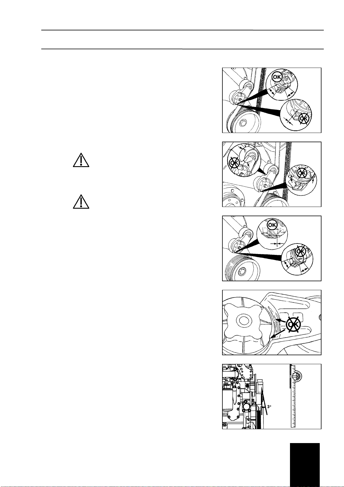
4.4.1 Cooling Fan Belt Tensioner
Fig. 4.4.1/1 to Fig. 4.4.1/5
Maintenance Check
With the engine turned off, check that neither the top nor bottom tensioner
arm stop is touching the cast boss on the tensioner body. If either of the
stops is touching a boss, the alternator belt must be replaced. Check to
make certain the correct belt part number is being used if either condition
exists.
Warning!
When using a steam cleaner, wear safety
glasses or a face shield, as well as protective
clothing. Hot steam can cause serious personal
injury.
Warning!
Wear safety glasses or a face shield, as well as
protective clothing, to prevent personal injury
when using a steam cleaner or high-pressure
water.
Check the tensioner pulley and body for cracks. If any cracks are noticed,
the tensioner must be replaced. Please ask your service representative.
Check the tensioner for dirt buildup. If this condition exists, the tensioner
must be removed and steam cleaned.
With the cooling fan belt removed, check that the bottom tensioner arm
stop is in contact with the bottom tensioner arm stop boss on the tensioner
body. If these two are not touching, the tensioner must be replaced.
Inspect the tensioner for evidence of the pivoting tensioner arm contacting
the stationary circular base. If there is evidence of these two areas touch-
ing, the pivot tube bushing has failed and the tensioner must be replaced.
The worn tensioner that has play in it or a belt that “walks” off its pulley
possibly indicates pulley misalignment.
Note: Maximum pulley misalignment is 3 degrees.
This measurement can be taken with a straightedge and an inclinometer.
Install the belt
Fig. 4.4.1/1
Fig. 4.4.1/2
Fig. 4.4.1/3
Fig. 4.4.1/4
Fig. 4.4.1/5
Table of contents
Popular Construction Equipment manuals by other brands

Fayat
Fayat DYNAPAC DRP15D Operating instruction

Norwood
Norwood LumberMax HD38 Original instructions

Manitowoc
Manitowoc GHC 75 Maintenance instructions

McElroy
McElroy TracStar 28 2 Auto Series Operator's manual

Generac Mobile
Generac Mobile CTF10 owner's manual

Blastrac
Blastrac BMS-150 operating instructions


S.D.P.
S.D.P. EZ Hauler 3000 Training & Procedure Manual

ALFIX
ALFIX MOBILE SCAFFOLD TOWER ALUFIX 200 Instructions for assembly and use

ASV
ASV SC50 Scout Service & repair manual

Velleman
Velleman IREXT2 user manual

MK Diamond Products
MK Diamond Products SRX-150 Owner's manual operating instruction & parts list

Tadano
Tadano GR-750XL-2 manual