Digga Cement Mixa Programming manual
1


1
THANK YOU
Congratulations on the purchase of your new DIGGA product! This product was carefully designed and manufactured to give you
years of dependable service. Only minor maintenance (such as visual checking) is required to keep it in top working condition.
Be sure to observe all safety precautions and maintenance procedures as described in this manual.
Contact your DIGGA dealer for any further information pertaining to this product or for further information on other products available
in the DIGGA range.
1 To The Purchaser

2Product Manual: Cement Mixa - June 2009
Table of conTenTs
1 To The Purchaser.........................................................................................3
2 Table of conTenTs .......................................................................................4
3 PreParaTion for use ...................................................................................5
4 insTallaTion and oPeraTing insTrucTions ..........................................5
5 MainTenance...................................................................................................8
WarranTy.........................................................................................................11
3
To avoid any inconvenience before operation, please check that you have received the following items which
you may have ordered. Items A & B may differ depending on type of Drive unit the mixa is tted to.
3 PreParaTion for use
REF DESCRIPTION QTY
A CEMENT MIX BOWL 1
B CEMENT MIXA ATTACHMENT CRADLE 1
C PINS 1
D LYNCH PINS -
OPTIONAL (if not already purchased)
E AUGER DRIVE UNIT 1
F STANDARD OR SCS CRADLE 1
A
B
C
D
E
F
C
SCS
PLEASE NOTE: FOLLOW ALL SAFETY PRECAUTIONS INSTRUCTIONS AS STATED IN YOUR DRIVE
UNIT OPERATORS MANUAL.

4Product Manual: Cement Mixa - June 2009
The DIGGA Cement Mixa attaches to the Auger Drive Unit on your Machine. Due to this arrangement, thorough knowledge of the
machinery controls is necessary for machine operation. Read and understand your machine operator’s manual for information regarding
machine operation before attempting to use the Cement Mixa.
Check the work site and identify the extent of the work to be carried out and note any possible hazards or constraints.
Review the job at hand and determine the Cement Mixa is appropriate for the intended conditions. For example: Do not use the Cement
Mixa to dig and carry material, or to lift heavy items
4 insTallaTion and oPeraTing insTrucTions
*Note If you purchased a new Auger Drive Unit with your Cement Mixa, please refer to the Drive unit operators manual for installation
before tting the Cement Mixa onto the Auger Drive unit.
1. Remove the shipping banding from around the cement mixa bowl and attachment cradle.
2. Remove any DIGGA augers from the auger drive unit. Ensure the auger is stored securely.
3. Place cement mixa bowl vertical (open end) on the ground. Raise the drive unit and crowd forward until the drive unit is hanging
vertically. Lower drive unit and insert drive shaft into cement mixa bowl hub. Fasten pin and lynch pin to secure cement mixa bowl.
4. Raise Drive unit and bowl, pin Cement Mixa attachment Cradle (Part No. - MI-000009) into place. Fasten pin and lynch pin to secure
cradle.
5. Raise the Complete cement mixa attachment, crowd back fully and lower to the ground resting on the cement mixa attachment cradle
foot. The unit is now ready for use.
CAUTION: USE A POSITIVE LIFT ARM LOCK TO SECURE THE ARMS IN PLACE. SERIOUS DAMAGE
OR PERSONAL INJURY COULD RESULT FROM LIFT ARMS ACCIDENTLY LOWERING
INSTALLATION INSTRUCTIONS

5
1. Position the cement mixa on solid level ground with the attachment cradle foot resting on ground.
2. Engage parent machine auxilary hydraulics to start the mixa before adding material.
3. Add material to the rotating drum. Leave the mixa running the entire time it contains cement.
DO NOT OVERLOAD THE MIXA!
4. Raise the loader arms and crowd forward to empty the drum while it is rotating.
5. Wash out all debris from the inside of the mixa.
OPERATING INSTRUCTIONS
1. Set the cement mixa bowl vertical (open end) on the ground and follow the standard shut down procedure in your loader
operators manual.
2. With the loader OFF, Remove the pin between the bowl hub and auger drive shaft. Raise the loader arms lifting the drive unit
from the bowl.
3. Raise the Drive unit and remove the pin between the auger drive cradle & the Mixa attachment foot cradle. Remove the foot cradle.
4. Place the Auger back onto the Drive unit if desired. For Drive Unit Removal please refer to the Drive unit operators manual.
CAUTION: USE A POSITIVE LIFT ARM LOCK TO SECURE THE ARMS IN PLACE. SERIOUS DAMAGE
OR PERSONAL INJURY COULD RESULT FROM LIFT ARMS ACCIDENTLY LOWERING
REMOVAL AND STORAGE
It is a requirement of the Australian Work place Health and Safety act 1995 that safe systems of work are employed when handling any
attachments. Complete compliance with Work place Health and Safety issues is compulsory and all due care and attention must be
observed at all times in any method of moving, transporting or storing any such device when not attached to a parent machine. We
recommend attachments are well secured when being moved or in transit and furthermore prior to moving, storing, loading/unloading or
parking it is suggested that the attachment is strapped/secured to a pallet or enclosed in a suitable container to minimise any movement
or loss of the load during such activity. NO responsibility for loss or damage to persons or property in any regard can be attributed to
Digga.
WHEN ATTACHMENTS NOT ON PARENT MACHINE:
TRANSPORTING THE ATTACHMENT
1. Follow all federal, state and local regulations when transporting the unit on public roads.
2. Use extra care when loading or unloading the machine onto a trailer or truck. Disconnect hydraulic couplers during transportation.
4 insTallaTion and oPeraTing insTrucTions

6Product Manual: Cement Mixa - June 2009
5 MainTenance
The key feature of your Digga Cement Mixa is low maintenance. It contains no user serviceable parts, unauthorised disassembly will
void warranty
● Make sure that all nuts and bolts are in place and properly tightened.
● Make sure that all other fasteners are in place and are performing their specied function.
● Make sure that all hydraulic ttings are tightened and that there are no leaks in any ttings or hoses.
● Make sure that all safety signs are in place, are clean, and are legible. (SEE THE SAFETY SIGN SECTION)
● Check for any Oil leaks
● Wear and tear on Pins, linkages, clips
● Replace any damaged parts and excessively worn parts.
● Use only manufacturer recommended replacement parts. Other parts may be substandard in t and quality.
● Always wear safety goggles or glasses when inspecting equipment
SAFETY FIRST!! READ AND UNDERSTAND THE SAFETY INSTRUCTIONS
BEFORE BEGINNING ANY DRIVE UNIT MAINTENANCE
BEFORE FIRST USE
BEFORE EACH USE
● Inspect the attachment for shipping damage. If damage does exist, do not operate until the damaged parts have been replaced
or repaired.
● Oil needs to be changed after 12 months or 1000 hours then every 2 years there after. Oil changes must be performed by an
Authorised Service Agent. Please Contact Digga for your nearest service location
EVERY 12 MONTHS
Escaping uid under pressure can have
sufcient force to penetrate the skin
causing serious personal injury. Fluid
escaping from a very small hole can be almost
invisible. Use a piece of cardboard or wood,
rather than hands to search for suspected
leaks. Keep unprotected body parts, such as
face, eyes, and arms as far away as
possible from a suspected leak. Flesh
injected with hydraulic uid may develop
gangrene or other permanent disabilities.
If injured by injected fluid, see a doctor at
once. If your doctor is not familiar with this
type of injury, ask him to research it
immediately to determine proper treatment.
WARNING! CARDBOARD
HYDRAULIC HOSE
OR FITTING
MAGNIFYING GLASS
Always wear safety goggles or glasses when inspecting equipment

7
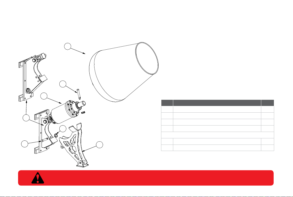
CEMENT MIXA SPARE PARTS
REF
NO. DESCRIPTION QTY ORDER CODE
B CEMENT MIXA ATTACHMENT CRADLE 1 MI-000009
C PIN 2 KIT-000001
D LYNCH PIN 1 KIT-000001
A
MIXA - 3.5 CU FT CEMENT MIXA - 75MM SQUARE HUB
1
MI-000020
MIXA - 3.5 CU FT CEMENT MIXA - 65MM ROUND HUB MI-000012
MIXA - 3.5 CU FT CEMENT MIXA - 57MM SQUARE HUB MI-000019
MIXA - 3.5 CU FT CEMENT MIXA - 2 HEX HUB MI-000018
MIXA - 2.2 CU FT CEMENT MIXA - 75MM SQUARE HUB MI-000017
MIXA - 2.2 CU FT CEMENT MIXA - 65MM ROUND HUB MI-000011
MIXA - 2.2 CU FT CEMENT MIXA - 57MM SQUARE HUB MI-000016
MIXA - 2.2 CU FT CEMENT MIXA - 2 HEX HUB MI-000015
E PDX - PD7 AUgER DRIvE UNIT 1 -
F SWINg CONTROL - SCS2 FULL ASSEMBLY STANDARD 1 SC-000144
F SWINg CONTROL - SCSX2 FULL ASSEMBLY EXCAvATORS 1 SC-000145
F SLIDE CRADLE TO SUIT FRAME 1 HI-000353
9 sPare ParTs
A
B
C
D
E
F
C
SCS
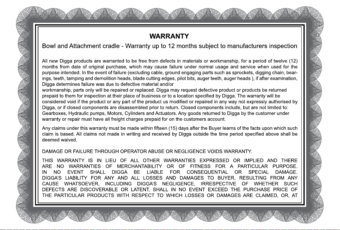
Table of contents
Other Digga Construction Equipment manuals


