digico SD7 User manual

SD7 Operation Manual
0-1
User Manual - Getting Started
To be read in conjunction with the SD Series Software Reference
UserManualVersionDforSoftwareVersions4.0.680+

SD7 Operation Manual
0-2
Copyright © 2014 Digico UK Ltd
All rights reserved.
No part of this publication may be reproduced, transmitted, transcribed, stored in a retrieval system, or translated into any
language in any form by any means without the written permission of Digico UK Ltd. Information in this manual is subject to
change without notice, and does not represent a commitment on the part of the vendor. Digico UK Ltd shall not be liable for any
loss or damage whatsoever arising from the use of information or any error contained in this manual.
All repair and service of the SD7 product should be undertaken by Digico UK Ltd or its authorised agents. Digico UK Ltd cannot
accept any liability whatsoever for any loss or damage caused by service, maintenance, or repair by unauthorised personnel.
Software License Notice
Your license agreement with Digico UK Ltd, which is included with the SD7 product, specifies the permitted and prohibited uses of
the product. Any unauthorised duplication or use of Digico UK Ltd software, in whole or in part, in print or in any other storage
and retrieval system is prohibited.
Licenses and Trademarks
The SD7 logo and SD7 name are trademarks, and Digico UK Ltd and the Digico UK Ltd logo are registered trademarks of Digico UK
Ltd. Microsoft is a registered trademark and Windows is a trademark of Microsoft Corp.
Digico (UK) Ltd
Unit 10
Silverglade Business Park
Leatherhead Road
Chessington
Surrey
KT9 2QL
England
Telephone: +44 (0)1372 845600
Fax: +44 (0)1372 845656
Email: [email protected]
WWW: http://www.digiconsoles.com
Manual Issue and Date: Issue D - April 2014 - For Version 4.0.680+ Software
Licence Agreement
"Product": SD7 software product produced by Digico UK Ltd intended for use on Target Platform identified below.
"Target Platform": Digico SD7 Digital Console system.
In return for the payment of the one-time fee, the Customer (identified at the end of this Agreement) receives from Digico UK
Ltd a licence to use the Product subject to the following terms and conditions.
1. The Product may be used without time limit by the Customer on the Target Platform.
2. The Customer must register the Product with Digico UK Ltd. Registering the Product is deemed an acceptance of the terms and
conditionsinthisagreement.
3. TheProductanditslicencearenottransferable, and the Customer is notpermittedtoonward-licensetoanythird party. The Cus-
tomerindemnifiesDigico UK Ltd againstanyand all claims andactionsarising from third partyuseof copies oftheProductmade by
theCustomer.
4. TheCustomeragreesnottoattempttodecompiletheobjectcodeoftheProductotherwisethanincircumstancesspecificallyprovided
forbylaw,andthen only after consultation withDigicoUKLtd.
5. TheCustomeragreesnottouse,orlicencetheProductforuse,with equipment other than the Target Platform.
6. TheCustomer agrees not to modifytheProductwithout the prior written consentofDigicoUK Ltd.
7. ThisAgreementappliestoanyenhancementorupgradesthatmaybecomeavailablefortheProduct.
8. This Agreement does not transfer any right, title, or interestintheProducttoCustomerexceptasspecificallysetforthherein.
9. DigicoUKLtdreservestherighttoterminatethisAgreementuponbreach,inwhicheventCustomershallthereafteronlybeauthorised
tousetheProducttotheextentthat itscontractualcommitmentstothird partiesrequireandthenonly wheresuchcommitmentsrelate
touseof theProductasauthorisedintheforegoing provisionsoftheAgreement.
LIMITED WARRANTY - Digico UK Ltd warrants for a period of 1 year from the date of purchase of the Product, the Product will reason-
ablyexecuteitsprogramminginstructionswhenproperlyinstalled ontheTargetPlatform. Intheevent thatthisProductfailsto executeits
programminginstructionsduringthewarrantyperiod,theCustomer's remedyshallbetoreturntheProducttoDigicoUKLtd forreplace-
mentorrepair at DigicoUKLtd option. Digico UKLtdmakes no otherexpresswarranty, whether writtenororal with respectofthis
Product.
LIMITATIONOFLIABILITY-Exceptasotherwiseexpresslyprovidedbylaw,(a)theremediesprovidedabovearetheCustomer'ssole
andexclusiveremediesand(b)DigicoUKLtdshallnotbeliableforanydirect,indirect,special,incidental,orconsequentialdamages
(includinglostprofitwhetherbasedonwarranty,contract,tort,oranyotherlegaltheory.)
Thisagreementis madeundertheLawsofEngland.
LICENCE NO:..................... ..........................................................
REGISTRATION DATE:..... ..........................................................

SD7 Operation Manual
0-3
Contents
1.1 The Console ............................................................................. .......1-1
1.2 Manual Overview ..................................................................... .......1-1
1.3 Before You Start ....................................................................... .......1-2
1.3.1 Worksurface Layout .............................................................1-2
1.3.2 Layers and Banks.................................................................1-3
1.3.3 Using the Control Surface ...................................................1-3
1.3.4 The Assigned Channel .........................................................1-4
1.3.5 The Master Fader ..................................................................1-5
1.3.6 Channel Types ......................................................................1-6
1.4 Hardware Configuration.......................................................... .......1-7
1.4.1 Connections..........................................................................1-7
1.5 Software Configuration ........................................................... .......1-8
1.5.1 Templates ..............................................................................1-8
1.5.2 Session Structure Overview ................................................1-8
1.5.3Audio I/O Overview................................................................1-9
1.5.4 Opto V220 (DiGiRacks) and Opto V221 (SD Racks) .........1-10
1.5.5Automatic Conforming .......................................................1-10
1.5.6 Network & Mirroring ...........................................................1-10
1.5.7 Single SD Console System ......................................... .......1-11
1.5.8 Manual Conforming of Racks ............................................1-12
1.5.9 Rack Sharing ......................................................................1-13
1.5.10 Assigning Faders to the Worksurface..................... .......1-14
1.6 Saving and Loading Sessions ............................................. .......1-15
1.7 Audio Sync .............................................................................. .......1-16
1.8 Routing Basics ..............................................................................1-17
1.8.1 Selecting Inputs & Outputs ................................................1-17
1.8.2 Ripple Channels .................................................................1-18
1.8.3 Channel Names ..................................................................1-18
1.9 Channel Processing.............................................................. .......1-19
1.9.1 Dynamic EQ ........................................................................1-19
1.9.2 Multiband Dynamics ...........................................................1-20
1.9.3Auxiliaries ............................................................................1-21
1.10 The Matrix............................................................................. .......1-22
1.11 Control Groups..................................................................... .......1-23

SD7 Operation Manual
0-4
1.12 Multi-channel formats.......................................................... .......1-24
1.13 Solo Setup....................................................................................1-25
SD7 - Getting Started
1-1
1.1 The Console
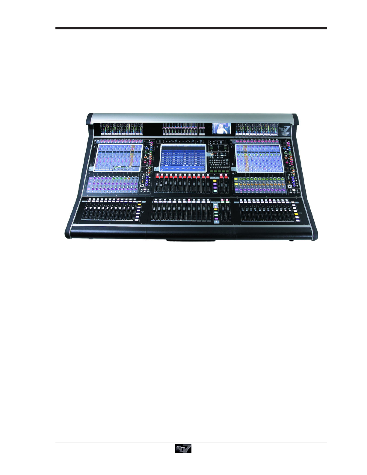
The Digico SD7 consists of a worksurface with dual redundant audio engines and a range of onboard inputs and outputs. This
can be connected to multiple Input/Output Rack Units by optical fibre and/or MADI links, which carry all the audio input and output
signals.
The console worksurface consists of 3 sections that can be configured to control up to 254 input/output channels, up to 36
VCAs, 128 busses and 32 Matrix Inputs and Outputs.
The left and right sections have 12 assignable faders and 12 sets of assignable on-screen channel controls, the centre section
has 24 assignable faders and 2 pairs of assignable master faders.
The console's buss architecture is dynamic, and can support mono, stereo, LCR, LCRS and 5.1 configurations.
Multiple console setups can provide:
Front of House and Monitoring with shared stage racks and gain tracking.
Remote control of one console from another console or from a laptop computer.
1.2 Manual Overview
This manual provides an overview of the desk, and describes some of the basic operating principles which the user will need to
understand in order to run the desk.
For full details on all SD software functionality please refer to the SD Series Software Reference Manual available for download
at www.digico.biz
The following typographical convention used in this manual: An arrow bracket (>) is used to indicate a sequence of button
pressing. For example, Layout > Fader Banks indicates that the
Fader Banks button is accessed by first pressing the Layout button.
SD7 - Getting Started
1-2
1.3 Before You Start
There are certain general operating principles and terms that should be understood before continuing to use this manual.
Please read this chapter carefully before proceeding.
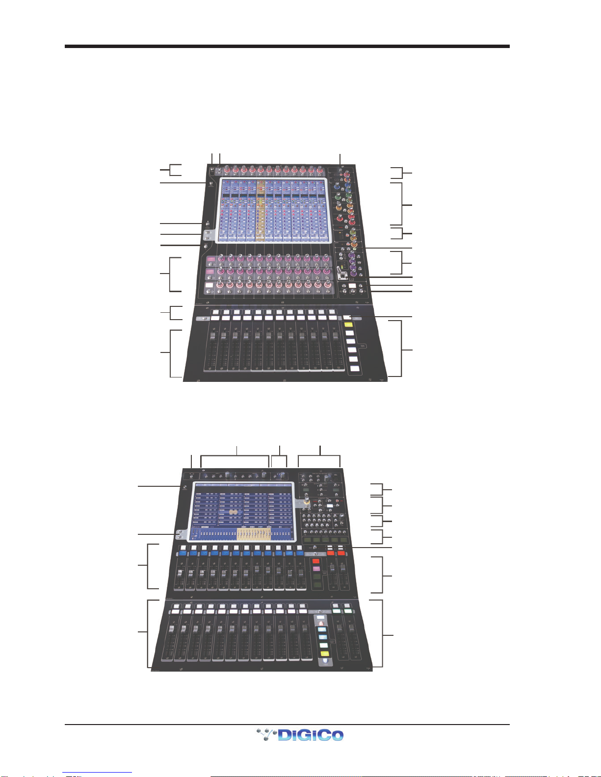
1.3.1WorksurfaceLayout..............................................................
Left & Right Sections
Input Gain and Phase
Rotary Resolution
Aux Scroll
Option/All
2nd Function
A
ssignable Rotaries and Switches
A
ux / Pan / Dynamics/FX Controls
Mute and Interactive LCD
Function Button
Channel Faders
ALT Input Switch
Assignable Rotary Scrollers
Meter View Switch
Channel InsertsA & B On/Off
Direct Out On/Off
4 Band Dynamic Parametric E
Q
High and Low Pass Filters
Multiband Dynamics
Thresholds & On / Off
Joystick
Dedicated Aux Rotaries
Hard Mute & Full Safe
Channel Scroll & Undo/Redo
Layer Switch
Channel Fader Banks
Centre Section
Rotary Resolution
Screen Scroll
Channel Faders/Mutes &
Graphic EQ Controls
LCD Function Buttons
C
hannel Faders/Mutes &
LCD Function Buttons
Video & Talkback
Phones
Solo 1 & 2 Controls
A/B Engine Switch
Dynamic Automation
Snapshot Controls
Macros
Monitoring Matrix
Fader Flip
Channel Fader Banks &
Assignable Master Fade
rs
Channel Fader Banks &
Assignable Master Fade
rs

SD7 - Getting Started
1-3
1.3.2 Layers and Banks .................................................................
The SD7's worksurface is divided into Layers and Banks. Each Bank contains twelve channels, and the channels which are
currently active on the control surface are defined using the fader bank and bank layer buttons to the right of the Channel Strip
section’s faders:
A ‘bank’ is a set of twelve faders, and a ‘layer’ contains up to six ‘banks’. There are up to 3 ‘layers’ in each section of the desk,
allowing up to 216 channels to be accessible on each worksurface section.
Pressing the bank layer button, located above the fader bank buttons, toggles between layers.
To access a bank of faders within that layer, press the appropriate fader bank button. To switch all three sections of the
console to the same bank level, press and hold one of the fader bank buttons.
The specific channels which are contained within each Bank is defined in the Layout > Fader Banks display. By default, the
Input channels will be assigned to Layer 1 on the left and right sections of the console. The different output channels will be
assigned to Layer 2 and also to the upper centre section. Control Groups will be assigned to the lower centre section. These bank
assignments can be customised by the user and saved in a session at any time. Holding any bank or layer button down for a
couple of seconds will switch all 3 worksurface sections to the same bank level or layer.
1.3.3 Using the Control Surface ....................................................
There are two main ways in which all of the functions of the SD7 are accessed:
1. The touchscreen display, which can be controlled directly using a finger, or by using the keyboard and mouse
2. The physical encoders, switches and faders.
Note that when touching the screen directly, you may find it easier to use a finer point than your finger.
However, in order to prevent damage to the screen, it is important that you only use devices specifically
designed for touching screens (such as a pda stylus), and that you never press down hard on the screen.
A number of functions can be accessed in different ways, allowing users to operate the console using whichever interface they
prefer. This manual will describe accessing on-screen functions by touching the screen directly and not by using the mouse.
All of the physical controls found in the centre section are described in full within the relevant section of the manual and many
require no further introduction.
The Master screen has a row of grey buttons accross the top, which are used to access a range of configuration displays.
Pressing these buttons opens either a further drop-down sub-menu or a pop-up display. If a drop-down menu is opened, pressing
on one of its entries will open a pop-up display. The buttons lighten to indicate that their sub-menu or pop-up display is open. A
number of the buttons within each pop-up display generate further pop-ups.
Generallly, buttons within the pop-ups are coloured grey when their function is inactive, switching to a colour when their function
is active. Pressing on a text box opens a numeric or QWERTY keypad which can be operated directly by pressing the screen or
via the console’s external keyboard.
Pop-ups are closed by pressing the box in the top right-hand corner of the pop-up, marked CLOSE or CANCEL (or by pressing
CAN on keypad pop-ups).
SD7 - Getting Started
1-4
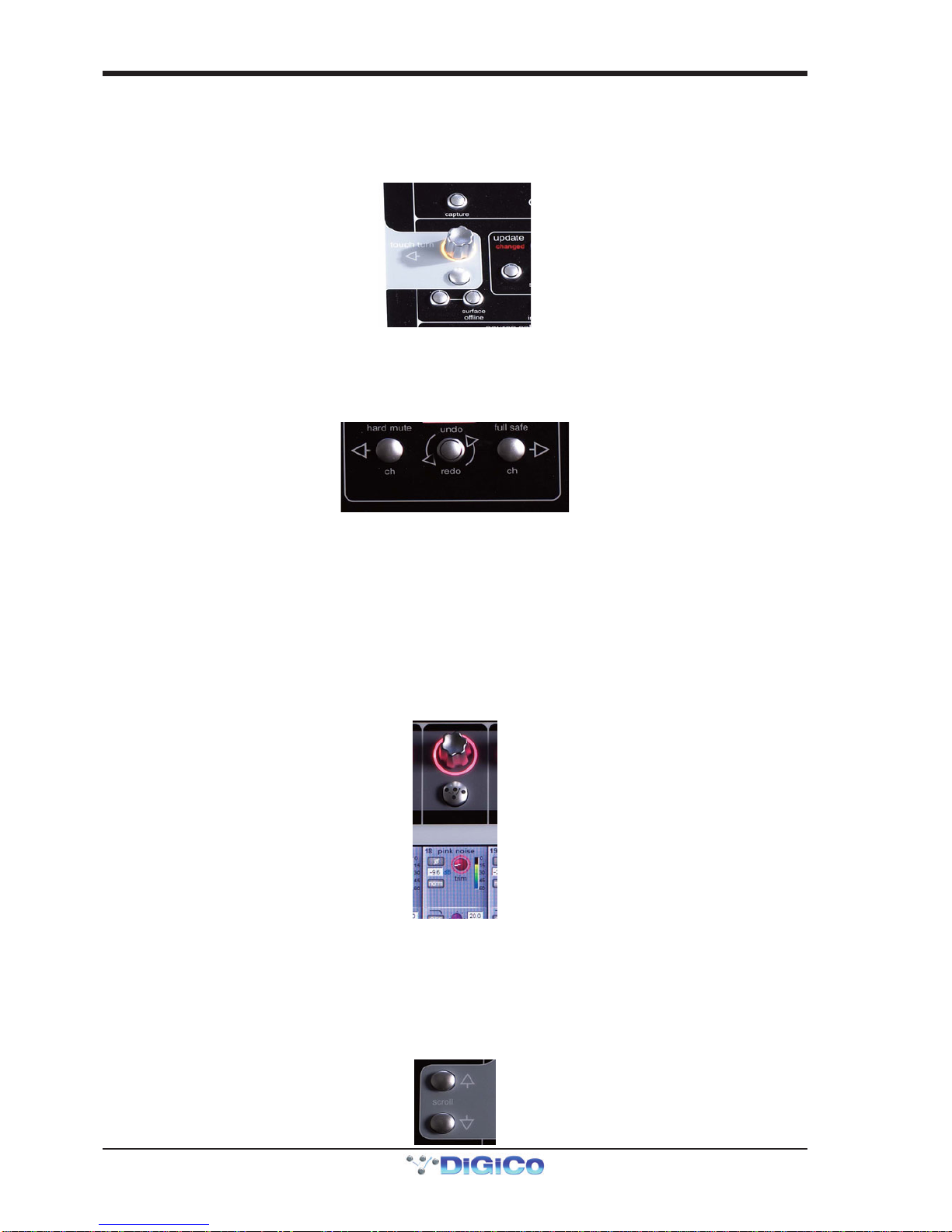
To the right of the Master Panel is a single encoder marked Touch-Turn (shown below). This is used to access any rotary
controls within the Master Panel. To assign the Touch-Turn encoder to a particular on-screen pot, touch the pot to be assigned.
You will notice that a coloured ring appears around the on-screen pot, indicating that it is assigned to the Touch-Turn encoder.
The colour of this ring is unique to that control, and is also reflected in the base of the Touch-Turn encoder, providing further
indication of which pot is currently assigned to it.
1.3.4 The Assigned Channel .........................................................
One of the channels in the Channel Strip panel is displayed in gold, indicating that it is currently the Assigned Channel. This means
that it has been assigned to the worksurface controls and can be configured in detail, as described below. To Assign a channel,
touch anywhere in the channel on the screen except the Aux Send area of the input channels. Alternatively, use the ch left and
right buttons at the bottom of the channel worksurface controls to scroll through the channels in the panel:
Note that these left and right arrows are duplicated in the channel Setup and Output displays.
Note also that the Channel List display provides another method for assigning a channel to the worksurface
controls.
Once a channel is Assigned, all of the controls for that channel which are not displayed within the channel strip itself can be
accessed via secondary pop-ups, displayed by touching inside the relevant area of the channel. These pop-ups include controls
such as input and output routing and signal processing parameters.
A number of the physical rotary encoders on the control surface can be assigned to different on-screen pots. In order to ensure
that it is clear which function is assigned to which encoder, the assigned on-screen pot will have a coloured ring around it which
will be reflected in the colour of the light around the base of the encoder on the control surface.
The twelve encoders and buttons immediately above the Channel Strip panel (shown above) refer to the channels with which
they are aligned. These controls are concerned with the channel input, located at the top of the Channel Strip panel.
The three rows of encoders and buttons immediately below the Channel Strip also refer to the channels with which they are
aligned. Normally, these control the level and on/off status of the three highlighted aux sends, but can have a number of functions
assigned to them. Touching on an aux send on the screen will assign that aux and the ones immediately below it to the aux
encoders. Six aux sends can be displayed in the Channel Strip panel at any one time. If more than six aux sends have been
created in the session, the scroll button outside the bottom left-hand corner of the screen can be used to scroll the display
through the remaining auxiliaries:
SD7 - Getting Started
1-5
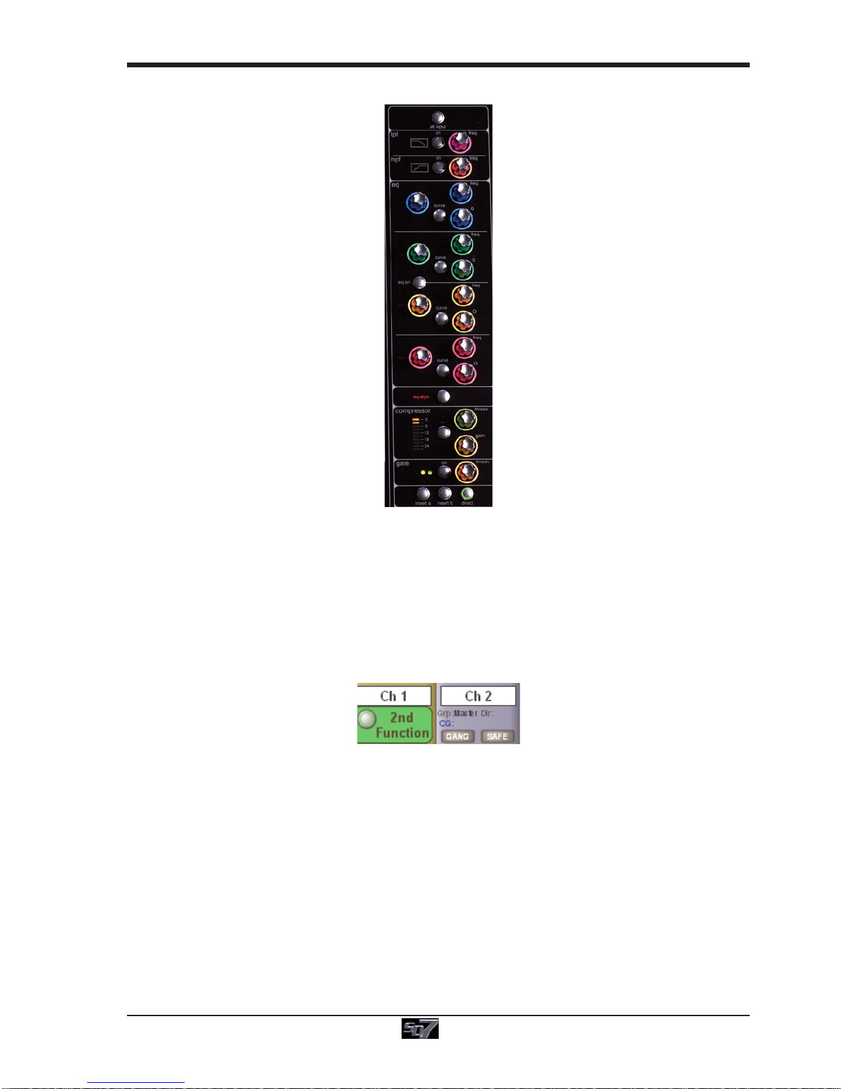
The controls to the right of the Channel Strip panel allow the Assigned channel to be adjusted:
The top half of the channel worksurface controls (down as far as the insert a, insert b and direct buttons, as shown above)
control the signal processing parameters which are displayed in the pop-ups accessed by touching in the appropriate section of
the active channel. The bottom half of the channel worksurface controls is concerned with output routing.
To the left of the Channel Strip panel are more channel controls: When pressed, the 2nd function button allows access to
different parameters:
1) Stereo Aux Pan and Pre/Post switching
2) Hard Mute of a channel
3) Switching of LR or LCR panning
4) Fine adjustment of Delay settings on output channels
2nd function is indicated by a green 2nd Function display appearing in the bottom left-hand corner of the screen, as well as by
the 2nd function button lighting with a ring of green.
The Option/All button has 2 main functions:
1) When pressed and released, any channel that is a member of a gang will be temporarily isolated from that gang.
2) When pressed and held, any parameter that is adjusted on a single channel will also be adjusted in the same way on all
of the channels in that bank
1.3.5 The Master Fader..................................................................
By default, the lower master faders are both assigned to the master group output, which is the lowest stereo group output by
default. In addition, the master faders can be assigned to the solo buss outputs. The ASSIGN FADERS function can be used to
assign any other function to these faders.
SD7 - Getting Started
1-6
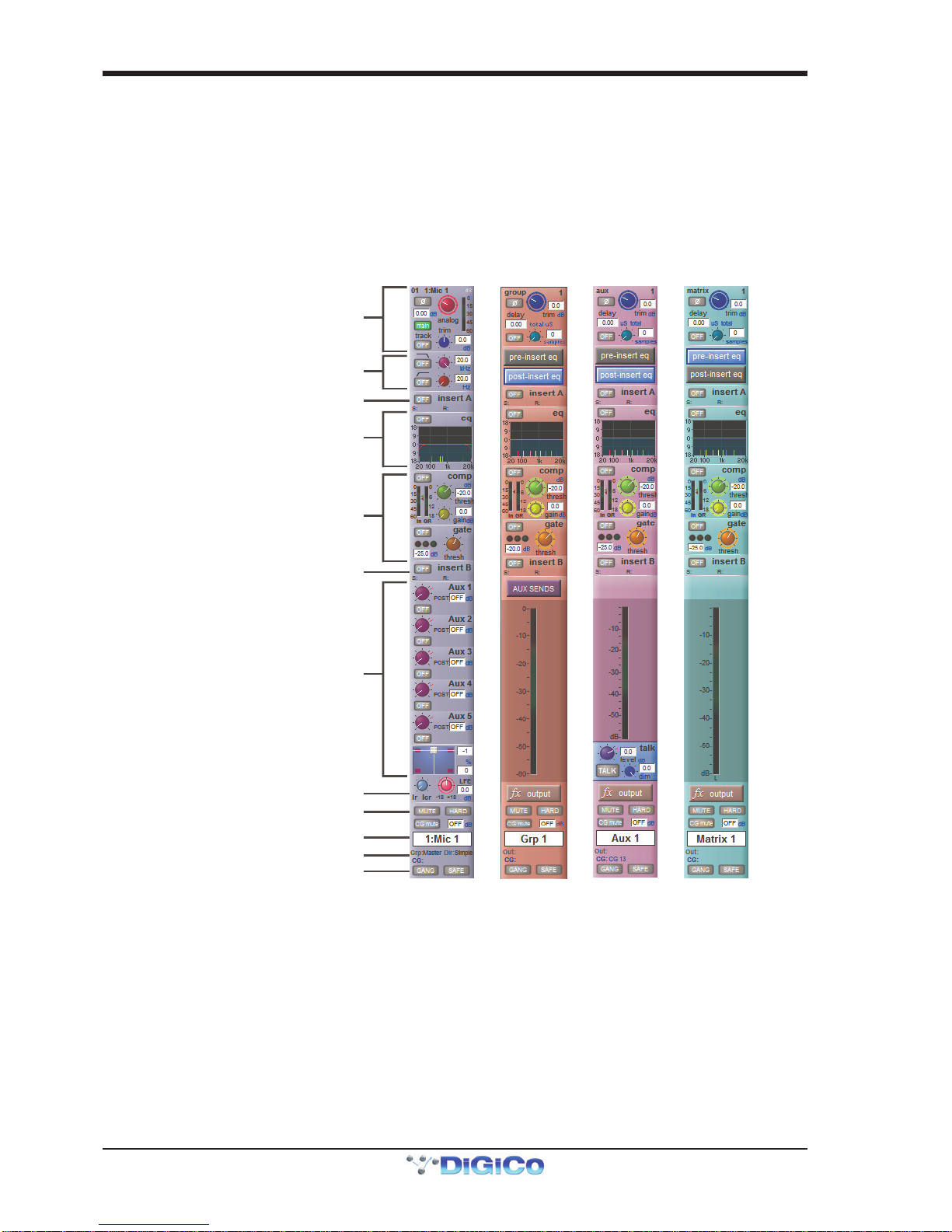
1.3.6 Channel Types ......................................................................
The SD7 has 4 different channel types which are laid out in banks of 12 on the console worksurface and can be identified by their
colour.
By default, the Input Channels will be assigned to Layer 1 on the left and right sections of the console.
The output channels (Groups, Auxes and Matrices) will be assigned to Layer 2 and also to the upper centre section.
Control Groups will be assigned to the lower centre section. These bank assignments can be customised by the user and saved
in a session at any time.
Holding any bank or layer button down for a couple of seconds will switch all 3 worksurface sections to the same bank level or
layer.
The controls on each different type of output channel are identical but an input channel has a number of additional features.
Input Module - Touch to Expand
Analogue Gain/Digital Trim
Phase - Gain Tracking
Main/Alt Input Select
Inputs
Insert A Routing & On/Off
HPF/LPF
4 Band Dynamic EQ
Touch To Expand
Multiband Dynamics
Touch To Expand
Insert B Routing & On/Off
Aux Sends
Touch toAssign Rows
Channel Pan
Mute Indicators
Channel Label
R
outing Module - Touch to Expand
Gang & Safe Indicators
Groups
Auxes
Matrix
SD7 - Getting Started
1-7
1.4 Hardware Configuration
1.4.1Connections ..........................................................................
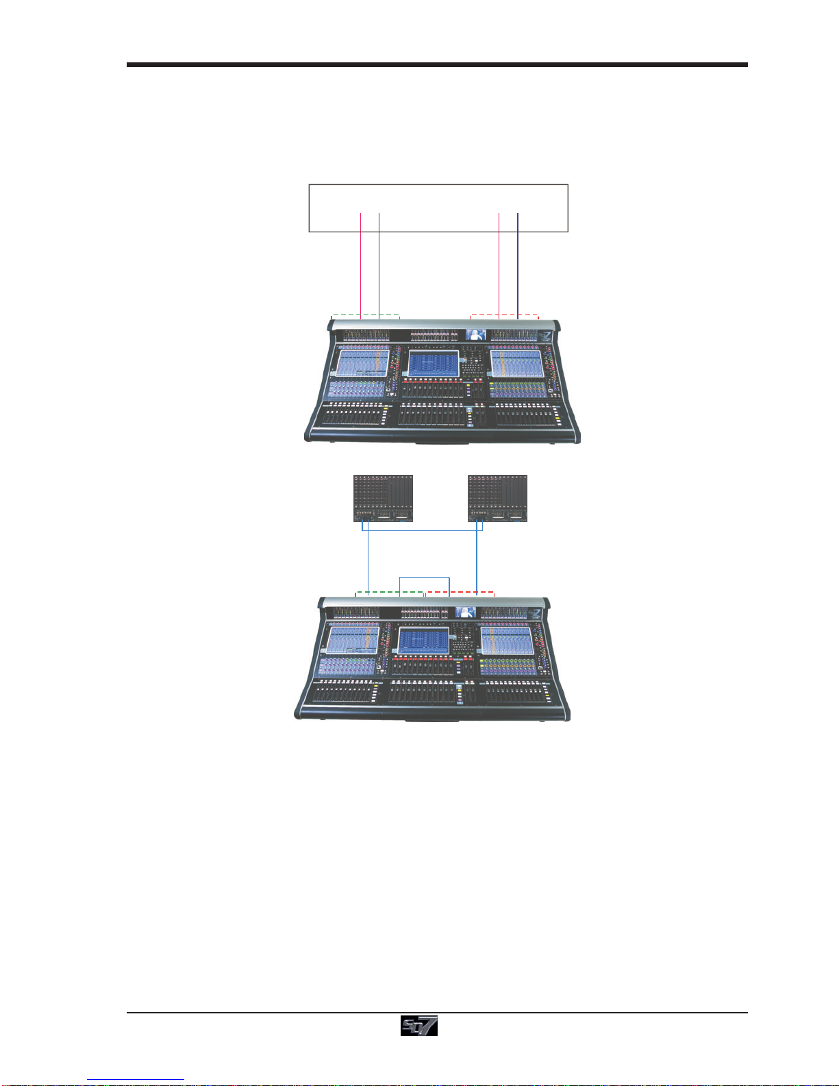
Detailed information on the various systems of connection is provided in the relevant Appendix but the following diagram provides
an overview of a single console/ rack setup.
MAIN MADI IN
CONNECTION WITH MADI
CONNECTION WITH OPTICAL FIBRE
OPTO A
OPTO A
OPTO B OPTO A
OPTIONAL
REDUNDANT
LOOP
OPTOA
OPTO B OPTO B
OPTO B
ENGINE A
ENGINE A
ENGINE B
ENGINE B
AUX MADI IN
ENGINEBMADIPORT1AOUT
ENGINEAMADIPORT1AOUT
ENGINEBMADIPORT1AIN
ENGINEAMADIPORT1AIN
MAIN MADI OUTAUX MADI OUT
DiGiRack / SD Rack
All connections should be made before switching on the console and racks.
The console and rack each have dual redundant power supplies and both should be switched on at all times. After switching on
the console the software will be launched automatically and the state of the worksurface and settings should be the same as
when it was last Shut Down.
To Shut Down the console press the System>Shut Down button and wait until you receive a message saying that it is safe to
switch the power off.
The SD7 worksurface has 12 analogue I/O and 12 AES I/O on its rear panel (referred to as Local I/O) and additional I/O is supplied
in the form of remote Racks which can each accommodate up to 56 inputs and 56 outputs in different formats. These racks are
connected to the worksurface by either 100M high specification 75 Ohm coaxial cables fitted with BNC connectors or optical fibre.
The Racks have two pairs of MADI connectors - Main MADI IN & OUT and AUX MADI IN & OUT.
In normal operation the MADI connections should be as follows (see diagram above):
Rack MAIN MADI IN connected to the console MADI 1A OUT
Rack MAIN MADI OUT connected to the console MADI 1A IN
Note - Optionally, a second set of MADI cables can be connected to provide MADI redundancy from the
rack's AUX MADI ports to the console's MADI 1B ports
The console's other MADI Ports can be connected to a MADI recorder (See Audio I/O Panel for setup details) or a second DiGiCo
Rack or console.
SD7 - Getting Started
1-8
1.5 Software Configuration
The SD7 has a default setup which means that the new user need not get involved in configuring the desk at this stage. However,
here is a brief overview of how the different displays are used in putting together a session. Each of the master displays intro-
duced below are described fully within the rest of the manual.
The Files > Templates display is used for loading pre-configured session templates.
The Files > Session Structure display is used for configuring how the console’s the audio channels are to be divided between
channel types, and where the format of the channels is defined
The Session Structure display can be used to automatically assign the channels to the worksurface. However, channels can
also be manually added to the worksurface using the Layout >Channel Faders display.
The Setup >Audio IO display is used to configure the physical I/O connected to the SD7, including configuring and naming the
sockets of the option cards installed in racks, and the setting of pads and phantom power.
1.5.1 Templates..............................................................................
If any templates have been created, they provide an easy starting point for sessions which are already customised to your
context. To load a session template, open the Session Templates display by selecting the Templates option at the top of the
Files menu. Now touch the template you wish to load from the list shown, and press OK.
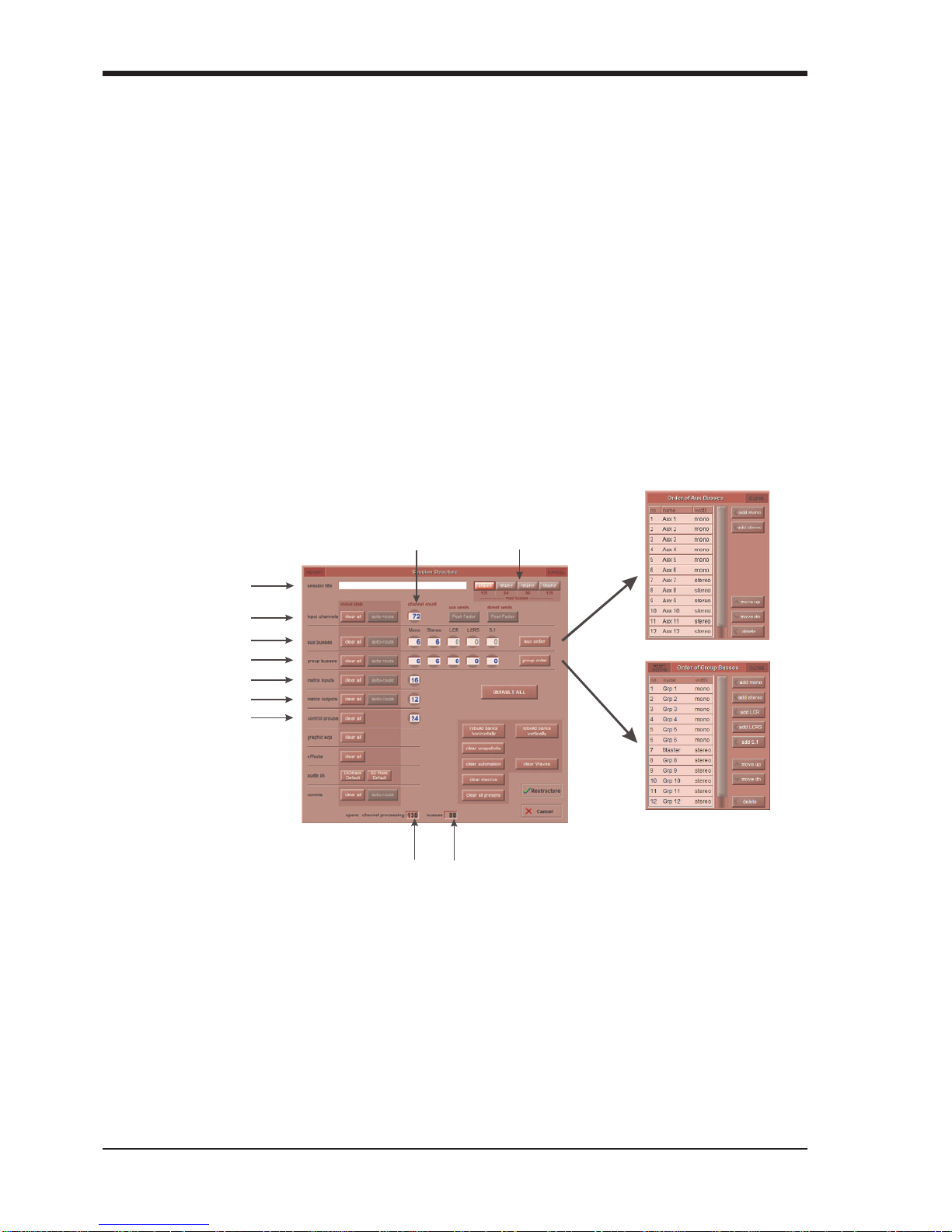
1.5.2 Session Structure Overview ................................................
When starting a new session from scratch, it is important to decide how many of each type of channel is required. While changes
to session structure can be made once a session has been started, it is best to try and set these parameters before configuring
the session. The structure will set items such as the number of input channels, the number and type of aux channels, group
channels and matrix channels available.
Total number
of unallocated
processing
Total number
of spare
busses
Touch number’s to
edit with pop-up
keypad or touchturn
Set number of Input Channels
Set number and type of Aux
S
et number and type of Group
Set number of Matrix Inputs
Set number of Matrix Outputs
Set number of Control Groups
Set Order of Aux and
Group busses
Enter Session title
Select session
sample rate
Begin by setting the sample rate and maximum buss number at the top of the panel. There are a total of 254 processing channels
available, up to 128 of which can be busses (output channels). Reducing the maximum buss number (available to 96kHz sessions
only) reserves a greater number of processing channels for use as input channels.
Channel resources can be split into input or output channels in almost any configuration. The default configuration is :
72 input channels (Input channel formats are defined within each channel, not within the Session Structure)
6 Mono Aux busses & 6 Stereo Aux busses
6 Mono Group busses & 6 Stereo Group busses
16 Matrix Inputs and 12 Matrix Outputs
24 Control Groups
Note that a Talkback channel is also assigned to the control surface, though it isn't configurable within the
Session Structure and is therefore not displayed there.
SD7 - Getting Started
1-9
To adjust any of the channel allocations, touch on the associated channel count box, and either enter a number using the pop-up
number keypad, or adjust using the assigned touchturn controller.
It is worth remembering that each output (buss) allocated also uses up one of your processing channels. So if, for example, you
were to allocate the maximum amount of busses, this would leave you with less input channels available.
Clear All Buttons : When changing routing, you have the option of clearing any non-default routing or processing (EQ, dynamics
etc) from the channels in the session. This is especially useful when restructuring an existing session to make a new session.
The other 'clear' buttons in the display perform similar operations.
Aux Sends and Direct Sends : By toggling the state of the Aux Sends and Direct Sends Buttons in the Input Channels
section, it is possible to change the default operation of the Aux Sends and Direct Sends. These functions toggle between “Post
Fader”, “Pre-Fader” and “Pre-Mute”.
Aux Order and Group Order : The Aux Order and Group Order buttons open a second window, providing you with the ability to
change the order of auxes and groups. By default, mono busses come first, followed by stereo busses. The Master buss is the
first stereo buss, regardless of the order you place the busses in.
Auto-Route : The Auto-route functions automatically routes consecutive inputs for input channels, and consecutive outputs for
busses. For example, auto-routing 72 inputs will route the first physical input (eg 1:Mic 1) to input channel 1, the second physical
input (1:Mic 2) to input channel 2… until you either run out of inputs or channels. Auto-routes are as follows :
Input Channels auto-route with physical inputs
Aux, Group and Matrix Channels auto route to physical outputs
Matrix Inputs auto-route with group outputs
NOTE : Auto-Routing can only be used in conjunction with the “Clear All” button.
Rebuild Banks : When changing the number of allocated channels in any section (input channels, busses etc), you can restruc-
ture the session without rebuilding banks, meaning that any additional channels you have allocated will not be “placed” on the
worksurface, and need to be manually assigned to faders. If however, you restructure a session with Rebuild Banks (either
Horizontally or Vertically) enabled, the worksurface will be built with all channels available on the worksurface in a default
layout. Rebuilding horizontally will result in input channels being spread accross the top layer of both sides of the console, using
as many banks as required, with output channels being assigned to Layer 2. Rebuilding vertically will result in input channels
being assigned to Layer 1 on the left side of the console, and output channels to Layer 1 on the right.
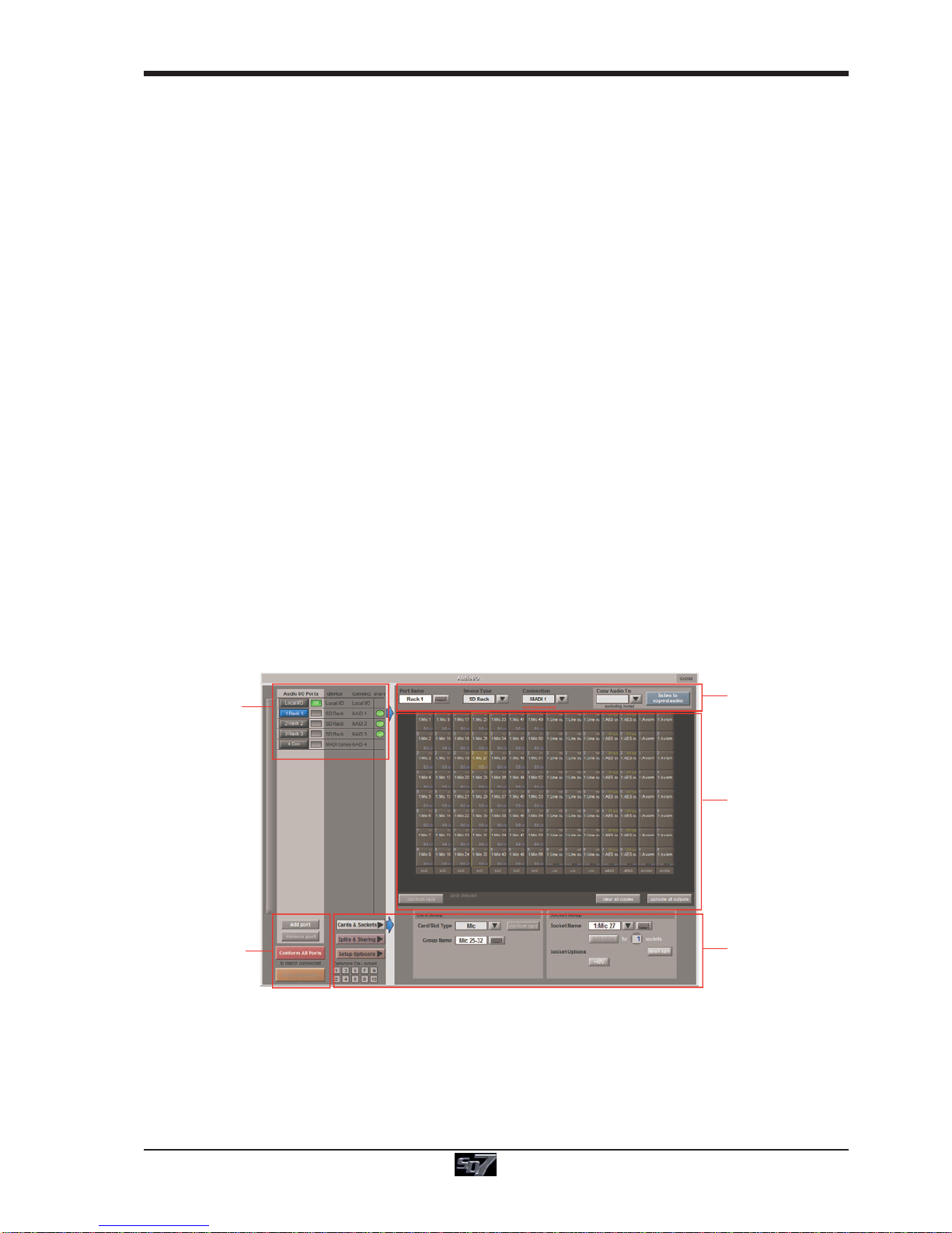
1.5.3 Audio I/O Overview ..............................................................
The Audio I/O window is used to configure the physical I/O connected to the SD7, including configuring and naming the sockets of
the option cards installed in racks, and the setting of Pads and phantom power.
Local I/O : The SD7 provides local audio I/O via 3 cards installed in the rear of the console. These operate independently of
connected racks, providing additional audio I/O.
To access the SD7 Audio I/O Setup Touch “Setup” on the Master Screen, followed by “Audio I/O”
The Audio I/O window that opens is divided up into the following sections:
Port Selection
and Status
Global Port
Management
Configuration of
Cards & Sockets
or Splits & Sharing,
as defined by
buttons to the left
Graphic
Representation of
Selected Rack
Selected Port’s
Properties
The top-left corner of the window shows the ports. Each port relates to an available physical audio connection (Local IO, IO Rack,
or MADI Port). Ports can be added and removed using the buttons towards the bottom-left corner of the window.
The top-right area contains the controls relating to specific ports. When a port is selected, this section changes to reflect the
status of the selected port, and allows its configuration to be changed as required.
Most of the right-hand section of the panel consists of a graphical representation of the rack configuration connected to the
selected port. Depending on the port selected, the graphic will change, showing the available physical I/O. Each small “square” on
the image represents a single physical audio connection or socket, with these arranged in columns or rows, representing I/O
cards in racks, or the local I/O on the back of the console.

SD7 - Getting Started
1-10
The section below the graphical rack picture allows configuration of either the cards or slots and sockets (including custom
naming, phantom power and pad selection), or card splits and control sharing. The Cards & Sockets and Splits & Sharing
buttons define which elements are displayed for configuration.
The local I/O configuration is fixed, so no hardware changes are possible. You can, however, change the Port Name, the Group
Names (relating to name of each physical card) and the Socket Names (the name of each physical connector on a card).
1.5.4OptoV220(DiGiRacks)and Opto V221 (SD Racks) .............
SD Series consoles can operate with either one of two different Optocore firmware versions - V220 and V221.
V220 is compatible with DiGiRacks and MiNiRacks and cannot be used with SD Racks or DRacks.
V221 is compatible with SD Racks, SD MiNiRacks, NaNoRacks and DRacks, and cannot be used with DiGiRacks and MiNiRacks.
Note: Any type of rack can be used with an SD Series console if it is connected with Coaxial BNC MADI irrespective
of the Optocore version that the console is using.
Sessions that have been created using Optocore connected DiGiRacks and MiNiRacks can be used with SD Racks and DRacks
but a procedure must be followed to acheive this.
Sessions created using Optocore connected SD Racks and DRacks can also be used with DiGiRacks and MiNiRacks but this also
involves a “conversion” procedure.
Note: For detailed information on Optocore system setup please refer to the user manual appendix - DiGiCo
Optocore V221 - For SD Rack Optocore Operation
1.5.5AutomaticConforming .........................................................
Once all hardware is connected, go to System/Diagnostics/Optocore. This will list all connected Optocore devices either SDeng
(console engines) to SDrack (SD Rack or D Rack) by ID. If any expected devices are not listed, please check all physical connec-
tions, Optocore ID’s and Fibre Speeds. Once all devices are present, close the Diagnostics panel.
Irrespective of the type of rack being used, the system needs to be conformed. This involves the console checking the type of
racks connected and their I/O capability
There are three levels of automatic conforming:
- globally, using the red Conform All Ports button in the bottom left of the window;
- on a rack-by-rack basis, using the conform rack button just below the rack view
section of the window;
- on a card-by-card basis, by selecting a socket from the card in the graphical display
and using the conform card button next to the Card/Slot type button selector in the
lower section of the window. (Note that the Cards & Sockets button towards the
bottom-left should be selected)
Pressing any of these buttons will correctly select the card types for the range in question. Once complete, all of the Card Labels
beneath each slot should turn green.
1.5.6 Network & Mirroring .............................................................
The SD7 console is fitted with two separate Engines, and as such, offers built in redundancy. In order to take advantage of this
redundancy, you need to verify the console networking is working, and synchronise your session between the two Engines.
Before the Engines can be mirrored, you should ensure that a standard cross-over network (Ethernet) cable is connected
between the two Engines. Without this connection, the two Engines will not “talk” to each other.
To open the Network window, touch the Network button at the top of the Master Screen.
Press here to Mirror To or From
the selected device
Press here to send a session
to the selected device
Press here to receive a session
from the selected device
Press the Select button to choose which
device to send to or receive a session from
When highlighted in orange
the Audio Master button indicates th
at
this audio engine is currently active
Once synchronised, session detail
for both Engines will match Optocore ID
As mentioned earlier in this chapter, if your console is equipped with Optocore connections, please check the Optocore IDs of the
engines before proceeding. Each console engine should have a unique Opto ID within the system
SD7 - Getting Started
1-11
The Optocore ID is set at the top of the on screen Network panel and should be as follows:
For Optocore V220:
First console A Engine = OPTO ID 0 - This engine can output to Optocore racks
First console B Engine = OPTO ID 1 - This engine can output to Optocore racks
Second console A Engine = OPTO ID 2 - This engine cannot output to Optocore racks
Second console B Engine = OPTO ID 3 - This engine cannot output to Optocore racks
For Optocore V221:
SD7 console engines are numbered in pairs eg 1&2 or 3&4 and up to 5 pairs (5 x SD7 consoles) can be connected at
the same time.
Consoles with single engines should be numbered either 1, 3, 5, 7, or 9.
Mirroring for the first time
The ENGINE A/B switch at the top of the centre worksurface will switch the entire worksurface from one engine’s control
computer to another. It will not (by default) switch the audio processing from one engine to the other. This is achieved by pressing
the relevant Audio Master button in the network window on either engine. When the button is orange, the engine is active.
There is an option in OPTIONS/SURFACE tab that enables the switching of both control computer and audio mastership at the
same time with the worksurface ENGINE A/B switch. When first configuring the system, we do not recommend running in this
mode
If the consoles are connected together, but do not see each other, then you may need to enable Networking.
There is an option in the OPTIONS/SESSION tab to ENABLE CONSOLE NETWORK (YES/NO). This must be set to YES on both
Engines. After doing this, shutdown and restart both engines and when the sessions are loaded go to the NETWORK window
and you should see yellow OK lights against Engine A and Engine B. This indicates that the network has connected the two
engines but they are not yet mirrored.
In order to mirror the two Engines, they need to be running the same session. The way to achieve this is to load the session into
the A Engine, then transfer it to the B Engine using the Network panel buttons as follows:
1. Ensure you are switched to the A Engine.
2. Load your session into Engine A
3. Open the Network panel
4. Press the Select button for Engine B and then press the Send Session To button.
This will copy your current Engine A session and load it into the B Engine. Once this is done, the Engine B detail section will
change to reflect the new loaded session. You can also check that this process is complete by switching the worksurface to the
receiving engine (using the A/B switch) and waiting for the progress bar to indicate that the session has finished building.
You can now press the Mirror To Selected button. The Mirror displays will turn green, and the console is now mirrored. Audio
Mastership can be switched between Engine A and Engine B using the Audio Master button and, assuming that the racks are
correctly connected, you will not hear the switch of between the two Engines.
1.5.7 Single SD Console System ..................................................
On an SD7, save your session, then open the Network panel, send the session to the second console engine and then mirror the
two engines.
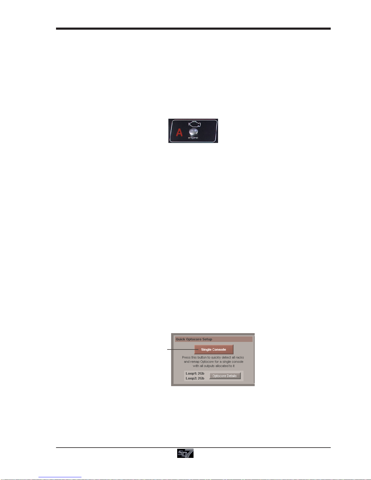
Go to Setup/Audio I/O. Press the Setup Optocore button and the Single Console button will be shown with a bright red back-
ground. Press this button, press Yes at the confirmation stage and the console will create ports for all connected racks, allocate
all output cards to your console and create the Optocore map. The system is now ready to use.
A
udio I/O Panel
O
ptocore Setup
Single Console

SD7 - Getting Started
1-12
1.5.8 Manual Conforming of Racks...............................................
With a Rack selected in the left hand port selection list, the window will look something like the image below, depending on the
cards installed in the connected rack. The graphic shows the 14 available cards/slots, 7 input & 7 output.
Edit the Port Name here.
Eg. Stage Rack, Local Rack etc...
Select Card Type manually or
using Auto-Conform function,
and edit Group Name
Selected Socket Properties
Edit Name and Socket options.
A
uto Conforming for all ports,
i
ndividual racks,
o
r individual cards
Select the contents of the bottom-right
corner of the Audio IO window
Select the port to be configured
Copy Rack Audio to MADI
In order to use the rack, the on-screen contents of the rack must match the cards physically installed in the rack connected. This
is normally acheived by pressing the Conform All Ports button but can also be acheived manually if necessary.
Select each card (column) and manually select the appropriate card in the Card/Slot Type drop down menu in the lower section of
the window (displayed when the Cards & Sockets button towards the bottom-left is selected). Once the correct card type is
selected, the Label at the bottom the selected card will turn green, indicating the card type matches the card installed in the rack. If
the Card Type name is Red, then there is a mismatch, and the error should be corrected by selecting the correct card type.
Copying Audio and Listening to Copied Audio (MADI Recorder Setup)
Audio from a Rack can be copied to the MADI Port Output by selecting the incoming Port in the Ports list and using the Copy Audio
To drop down menu. For example, if you want to copy the Rack Audio Inputs to a recorder connected over MADI, select Rack 1
in the ports list and then select MADI from the Copy Audio To drop down menu. The 56 inputs on Rack 1 will be copied to the
SD7 MADI output.
In addition, by connecting the recorder's MADI Output to the SD7 MADI Input, the playback can be monitored in the same channels
as the original source material. Just press the Listen To Copied Audio button to monitor playback and press it again to return to
monitoring the live sources from the rack.
StandardMADIConnections
If you have a standard MADI connection (not a DiGiCo Rack) to your SD7, you can set the console to display the MADI with
generic signal names, i.e. MADI 1, MADI 2.. etc. through to MADI 56 (or 64) instead of the usual rack style names. The naming does
not affect the signal, but makes routing signals easier.
UnroutingAllOutputs
All outputs to the selected port can be unrouted at once by pressing the unroute all outputs button below the cards graphic
and selecting yes in the warning pop-up which appears. "Copied" audio is not unrouted by this action.
Note that this will cancel all routing created in the channel screens and cannot be undone.
SD7 - Getting Started
1-13
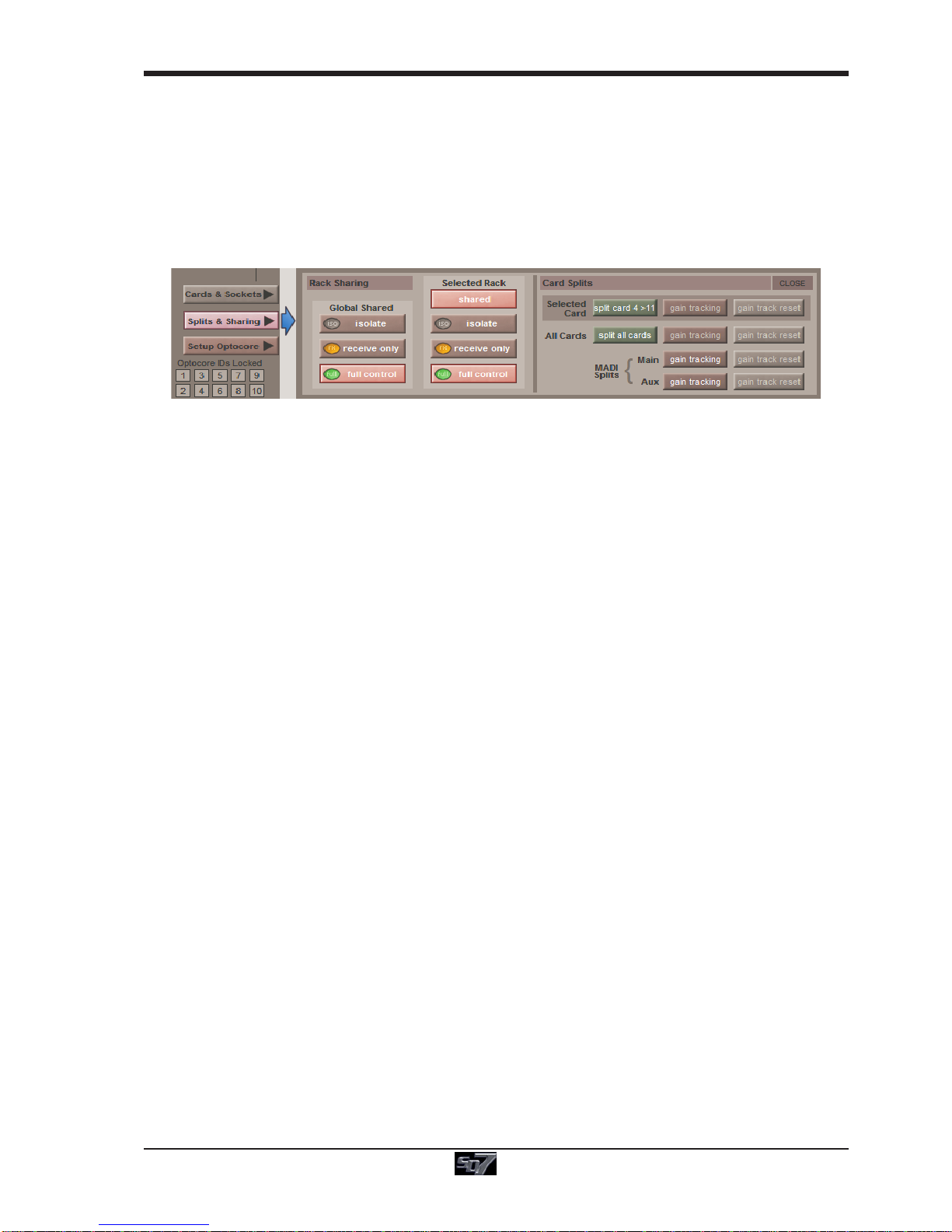
1.5.9 Rack Sharing.........................................................................
In a multi-console system where Racks are connected with MADI and shared between two DiGiCo Consoles, only one of the
consoles can take control of the rack, with respect to Gain, Phantom Power and Pads. To overcome this, it is possible to place the
SD7 into one of 3 states of operation:
Isolate : The SD7 will not communicate with the rack and therefore any adjustment of input gain or +48V switch will have no
effect on the rack settings
Receive Only : The SD7 will receive the rack’s existing settings but will not be able to control the gain etc on the racks.
Full Control : The SD7 will send its settings to the racks and change them accordingly.
Sharing is configured in the Rack Sharing area, found in bottom right-hand corner of the window when the Splits & Sharing
button is selected:
These three states can be set on a per-rack basis (right column), or globally for all shared racks (left column).

SD7 - Getting Started
1-14
1.5.10AssigningFaderstotheWorksurface................................
If, after a Session Restructure, you find that newly created channels do not appear on the worksurface, open the Layout/
Channel List panel on the Master screen and you will see a full list of all input and output channels that are present in the
session.
To assign channels to the worksurface, select a bank and press the LCD Function button.
Then press the LCD button labelled Assign Faders to enter that mode and press each of the LCD buttons for the channels that
you wish to assign.
Now press the first channel that you wish to assign on the Layout/Channel Faders list on the Master screen.
Consecutive channels will be assigned to the worksurface for each LCD button that is in Assign mode.
Now press the LCD Function button again and return to the standard mode by pressing the LCD button labelled Solo
Note that column widths can be adjusted by dragging their borders within the title row. To return all col-
umns to their default widths, press RESET WIDTHS, in the top left-hand corner of the window.
Touch first channel
to assign
Press LCD Function button
then Assign Faders
Press LCD button(s)
forAssignment
Open
L
ayout/Channel Faders
Click down arrow
to expand list
SD7 - Getting Started
1-15
1.6 Saving and Loading Sessions
1.6.1 Save As New File .................................................................
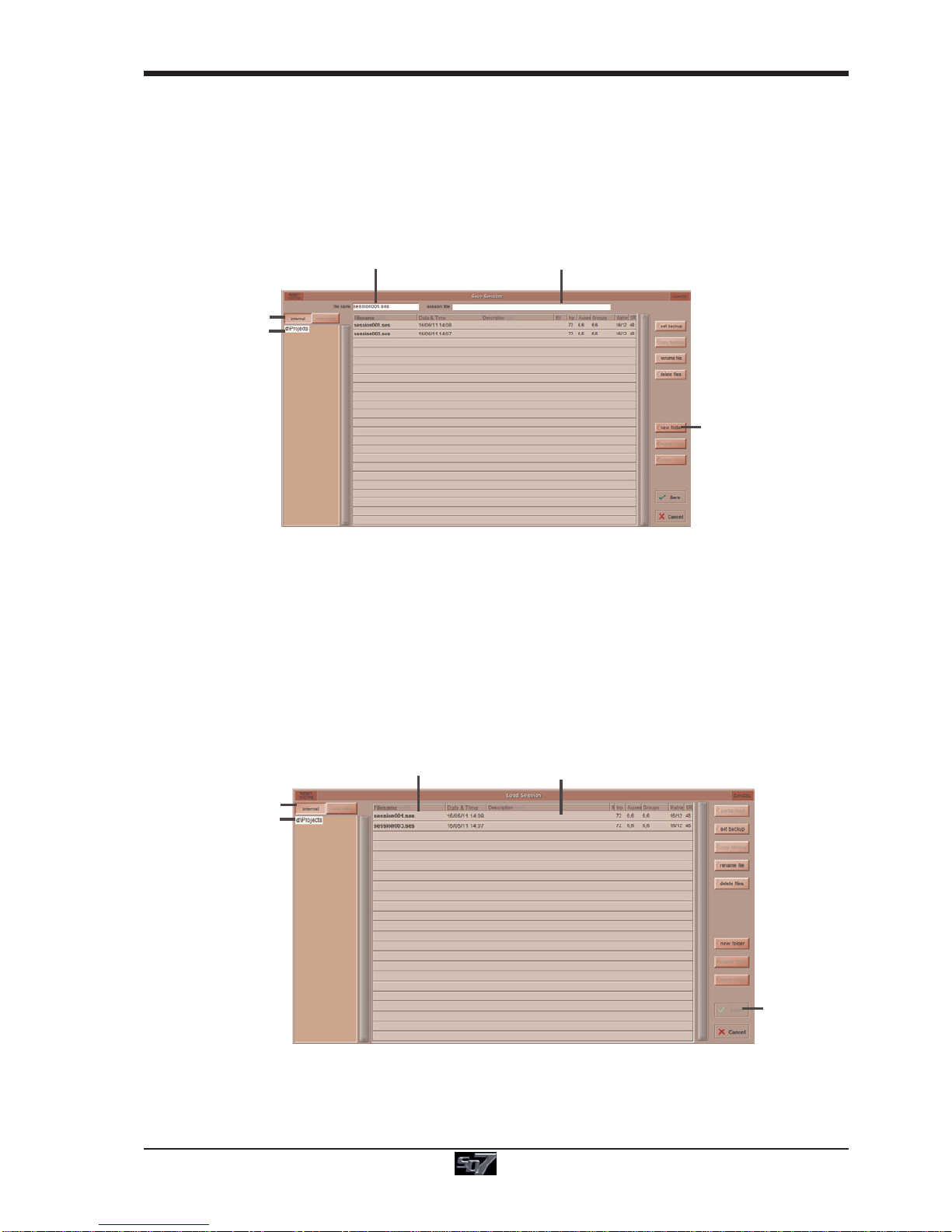
When you change the configuration of a session you should save it to the console's flash drive under a new filename.
If the Save Session panel has not appeared automatically after a session restructure then touch the Files button on the Master
screen and then press Save As New File.
Select the destination drive (Internal or Removable) and file path and then enter a new file name and description for the file - then
press the Save button.
Note: If you touch a session name on the existing list, this name will automatically be selected as the new file
name and touching Save will overwrite the old file.
Enter a Filename
Enter a Description
I
nternal files saved
in D:\Projects
Select Internal or
Removable USB
To create a new folder
in D:\Projects
Note that column widths can be adjusted by dragging their borders within the title row. To return all col-
umns to their default widths, press RESET WIDTHS, in the top left-hand corner of the window.
1.6.2 Save Session ........................................................................
This button which is found above the Save As New File button will save the existing session in the same location and under the
same file name as it was previously saved or loaded from. It therefore serves as a "Quick Save" option to update an existing
session.
Remember that this function will overwrite your last saved version.
If you wish to save the session under a new name use the Files menu button and select Save As New File (See above).
1.6.3 Load Session ........................................................................
To load a previously saved session:
Touch the Files button on the Master screen and then press Load Session.
Select the source drive (Internal or Removable) and the required file from the list - then press the Load button.
Select a File
File Details
I
nternal files saved
in D:\Projects
Select Internal or
Removable USB
Press Loa
d

SD7 - Getting Started
1-16
1.7 Audio Sync
To access the Audio Sync Panel, touch the Setup Menu button, followed by Audio Sync. The following window will open…
The SD7 will operate at Sample Rates of either 48000Hz (48kHz) or 96000Hz (96kHz), as configured in the Session Structure
panel.
By default, it is set to clock internally but the standard Audio Sync method is Optocore when the entire system uses the device
with the lowest Optocore ID (usually ID1) as its sync source.
This setting is saved within the session file so if any console(s) are connected to racks with optical fibre then all console engines
should be set to Optocore as their sync source.
ExampleClockingfromOptocore@96kHz
There are also times when the SD7 needs to be clocked externally. The Audio Sync panel allows you to control external synchro-
nisation.
The SD7 will clock from the following sources : Word Clock, AES/EBU, Video Reference, MADI & Optocore
In this situation one Optocore device should be set to clock to the external source and all other Optocore devices should be set to
sync to Optocore.
Note : When a valid clock is detected on an external sync input, the corresponding Green OK box will light,
even if that input is not selected as the clock source for the SD7.
Other manuals for SD7
1
Table of contents
Other digico Dj Equipment manuals


