digico S21 User manual
1
DiGiCo S21
DiGiCo S21 Getting Started
Version B for Software Version 1.0

DiGiCo S21

3
DiGiCo S21
Copyright © 2015 Digico UK Ltd
All rights reserved.
No part of this publication may be reproduced, transmitted, transcribed, stored in a retrieval system, or translated into any language in
any form by any means without the written permission of Digico UK Ltd. Information in this manual is subject to change without notice,
and does not represent a commitment on the part of the vendor. Digico UK Ltd shall not be liable for any loss or damage whatsoever
arising from the use of information or any error contained in this manual.
Software License Notice
Your license agreement with Digico UK Ltd, which is included with the S21 console product, species the permitted and prohibited uses
of the product. Any unauthorised duplication or use of Digico UK Ltd software, in whole or in part, in print or in any other storage and
retrieval system is prohibited.
Licenses and Trademarks
The S21 logo and S21 name are trademarks. Digico UK Ltd and the Digico UK Ltd logo are registered trademarks of Digico UK Ltd.
Digico (UK) Ltd
Unit 10
Silverglade Business Park
Leatherhead Road
Chessington
Surrey
KT9 2QL
England
Telephone: +44 (0)1372 845600
Fax: +44 (0)1372 845656
Email: [email protected]
WWW: http://www.digico.biz
Manual Issue and Date: Issue B - September 2015 - For Version 1.0
Software Licence Agreement
"Product": S-Series software product produced by Digico UK Ltd intended for use on Target Platform identied below.
"Target Platform": Digico S-Series Digital Console systems.
In return for the payment of the one-time fee, the Customer (identied at the end of this Agreement) receives from Digico UK Ltd a
licence to use the Product subject to the following terms and conditions.
1. The Product may be used without time limit by the Customer on the Target Platform.
2. The Customer must register the Product with Digico UK Ltd. Registering the Product is deemed an acceptance of the terms and
conditions in this agreement.
3. The Product and its licence are not transferable, and the Customer is not permitted to onward-license to any third party. The Cus-
tomer indemnies Digico UK Ltd against any and all claims and actions arising from third party use of copies of the Product made by
the Customer.
4. The Customer agrees not to attempt to decompile the object code of the Product otherwise than in circumstances specically pro-
vided for by law, and then only after consultation with Digico UK Ltd.
5. The Customer agrees not to use, or licence the Product for use, with equipment other than the Target Platform.
6. The Customer agrees not to modify the Product without the prior written consent of Digico UK Ltd.
7. This Agreement applies to any enhancement or upgrades that may become available for the Product.
8. This Agreement does not transfer any right, title, or interest in the Product to Customer except as specically set forth herein.
9. Digico UK Ltd reserves the right to terminate this Agreement upon breach, in which event Customer shall thereafter only be author-
ised to use the Product to the extent that its contractual commitments to third parties require and then only where such commit-
ments relate to use of the Product as authorised in the foregoing provisions of the Agreement.
LIMITED WARRANTY - Digico UK Ltd warrants for a period of 1 year from the date of purchase of the Product, the Product will reason-
ably execute its programming instructions when properly installed on the Target Platform. In the event that this Product fails to execute
its programming instructions during the warranty period, the Customer's remedy shall be to return the Product to Digico UK Ltd for
replacement or repair at Digico UK Ltd option. Digico UK Ltd makes no other express warranty, whether written or oral with respect of
this Product.
LIMITATION OF LIABILITY - Except as otherwise expressly provided by law, (a) the remedies provided above are the Customer's sole
and exclusive remedies and (b) Digico UK Ltd shall not be liable for any direct, indirect, special, incidental, or consequential damages
(including lost prot whether based on warranty, contract, tort, or any other legal theory.)
This agreement is made under the Laws of England.
LICENCE NO: ...................................................................................
REGISTRATION DATE: ....................................................................

DiGiCo S21
Contents
1.1 The Console .......................................................................................1-1
1.2 Before You Start ................................................................................1-2
1.2.1 Worksurface Layout .............................................................1-2
1.2.2 Layers and Banks .................................................................1-3
1.2.3 Using the Control Surface ...................................................1-3
1.2.4 The Selected Channel ..........................................................1-4
1.2.5 The Under Screen Controls .................................................1-4
1.3 The Expanded Views .........................................................................1-5
1.3.1 Display Expanded Views .....................................................1-5
1.3.2 Channel Setup View .............................................................1-6
1.3.3 Group and Aux Setup View..................................................1-7
1.3.4 Input Routing View ...............................................................1-7
1.3.5 EQ View .................................................................................1-8
1.3.6 Dynamics 1 View ..................................................................1-9
1.3.7 Dynamics 2 View ................................................................1-10
1.3.8 Control Group Setup ................................................... .......1-11
1.3.9 Solo Channel Setup............................................................1-12
1.4 Customising the Layout ..................................................................1-13
1.4.1 The Console Overview ......................................................1-13
1.4.2 The Spill Set .......................................................................1-13
1.4.3 Swap Banks .......................................................................1-14
1.4.4 Set Master ..........................................................................1-14
1.5 The Main Menu .................................................................................1-15
1.5.1 Session Management .........................................................1-15
1.5.2 Snapshots ...........................................................................1-16
1.5.3 Preferences .........................................................................1-18
1.5.4 Audio Sync ..........................................................................1-18
1.5.5 Macros .................................................................................1-19
1.5.6 FX Rack ...............................................................................1-19
1.5.7 Graphic EQs ........................................................................1-20
1.5.8 Matrix ...................................................................................1-20
1.5.9 System .................................................................................1-21
1.5.10 Diagnostics .......................................................................1-22
1.5.11 Restart or Shutdown ........................................................1-22
1.5.12 Upgrading Software .........................................................1-22

1-1
DiGiCo S21
1-1
1.1 The Console
The Digico S21 consists of a worksurface, an audio engine and a range of onboard inputs and outputs. It can be connected using op-
tional DiGiCo DMI Cards to a variety of DiGiCo racks and other audio input/output devices.
The console worksurface consists of 2 sections that can be congured to control up to 40 mono or stereo input channels, 10 VCAs, 16
mono or stereo busses plus a Master buss and a 10 Input x 8 Output Matrix.
The left and right sections have 10 assignable faders and 10 sets of assignable on-screen channel controls, the right hand section
also has a dedicated Master fader and mute, a Master/Solo meter, a set of 6 assignable encoder/switches and worksurface navigation
controls
The console's buss architecture is dynamic, and can support mono and stereo congurations.
Multiple console setups can provide:
Front of House and Monitoring with shared stage racks and gain tracking.
DiGiCo S21
1-2
1.2 Before You Start
There are certain general operating principles and terms that should be understood before continuing to use this manual.
Please read this chapter carefully before proceeding.
IMPORTANT NOTES:
S21 V1.0 software is not compatible with any sessions created in preliminary (pre V1.0) versions of software
Please delete all old sessions to avoid potential issues and create a "New" session in V1.0.
The console power switch is situated on the rear panel.
Please ensure that any required DiGiCo I/O racks are connected to the console DMI cards and powered on before start-
ing the console itself to enable automatic discovery of the racks.
DMI cards are NOT "Hot swappable" so please ensure that the console is powered off before inserting or removing
them.
We recommend that the rst snapshot is used as a "Setup" Snapshot where all of your "session wide" settings like
routing, Control Group membership and Buss Modes (whether Busses are Groups or Auxes) are rst stored.
Because these types of setting can be changed with Snapshot recall, it is advisable to save them all into this rst
snapshot before creating any further Snapshots. In this way, the settings for all subsequent Snapshots will contain the
same data and there should be less requirement to adjust the Safe settings in the channels.
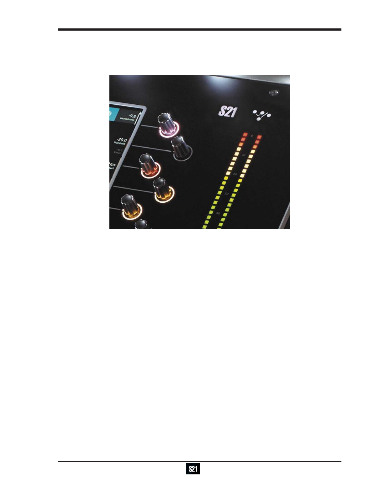
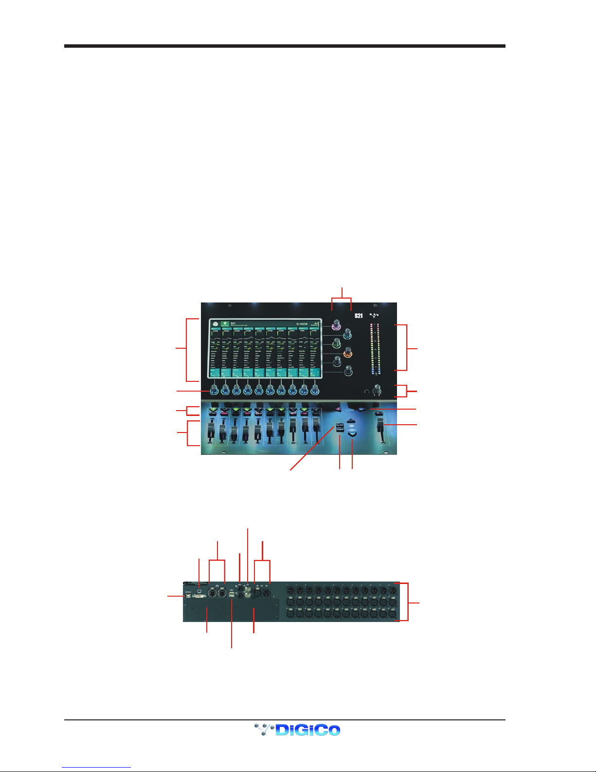
1.2.1 Worksurface Layout ...............................................................
MultiTouch Screen
Assignable Encoder/Switches
Solo & Mute
Channels Faders
Assignable Encoder/Switches
Snapshot Previous/Next
Master/Solo Meters
Headphone Level
Master Fader
Layer Up/Down
Spill Set Overview
Rear Panel
UB MADI Connector
DMI Slot 1 DMI Slot 2
DVI Screen Output
SEE NOTE BELOW
Console Ethernet
Console USB
AES I/O
GPI/O
Word Clock I/O
12 Line Out
24 Mic/Line In
IMPORTANT NOTE: The DVI Screen output will display a copy of the Master (right hand) screen but this must be
connected to the HDMI input of a suitable monitor using a standard DVI to HDMI adaptor (not supplied).
IMPORTANT NOTE: The GPI/O functionality is not yet implemented in V1.0
1-3
DiGiCo S21
1-3
1.2.2 Layers and Banks ...................................................................
The S21's worksurface is divided into Layers and Banks. Each Layer contains 2 Banks of 10 channels, and the layer which is currently
active on the control surface is selected using the layer up and down buttons next to the Master fader.
The right hand screen is referred to as the Master Screen and this is where the various expanded views of elements such as EQ and
Dynamics are displayed.
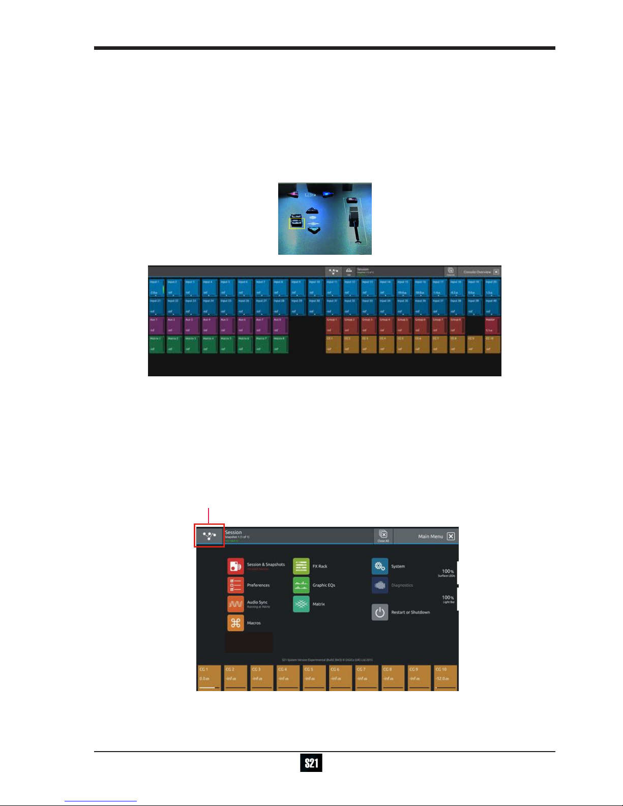
Pressing the white Overview button, located near the layer up and down buttons displays an on screen representation of all console
channels and the active layer can also be selected by touching it on the screen in this mode.The specic channels which are contained
within each Bank are dened in the Overview display. By default, the Input channels will be assigned to Layers 1 and 2 on the left and
right sections of the console.
The different output channels will be assigned to Layer 3 and 4. Control Groups will also be assigned to Layer 4. These bank assign-
ments can be customised by the user and saved in a session at any time.
1.2.3 Using the Control Surface .....................................................
There are two main ways in which all of the functions of the S21 are accessed:
1. The touchscreen display, which can be controlled directly using a nger
2. The physical encoders, switches and faders.
A number of functions can be accessed in different ways, allowing users to operate the console using whichever interface they prefer.
All of the physical controls on the console worksurface are described in full within the relevant section of the manual and many require
no further introduction.
The right hand Master Screen has a DiGiCo logo icon at the top which is used to access the Main Menu
Main Menu

DiGiCo S21
1-4
1.2.4 The Selected Channel ............................................................
One of the channels in the Channel view is displayed with a highlighted background, indicating that it is currently the Selected Channel.
This means that it has been assigned to the worksurface controls to the right of the screen as shown in the image below. To assign a
channel, touch in the Output Block at the bottom of the on screen Channel view
NOTE: All of the master and under screen rotaries are encoders and switches in one unit.
Often, different functions can be accessed by a standard turn, a push turn and a push (switch)
eg Standard turn = Gain control & Push turn = Trim control
Assignable Encoder/Switches
Selected Channel
Compressor Threshold
Gain & Trim (Push Turn)
HPF
Gate Threshold
Aux Pan (Stereo)
Aux Level
Output Block area
Touch here to select a channel
NOTE: When the right hand screen is not displaying the Channel view (eg it is displaying an EQ view), the master
screen worksurface rotaries will not be assigned to the Channel view controls but to the controls for the EQ or other
expanded view instead.
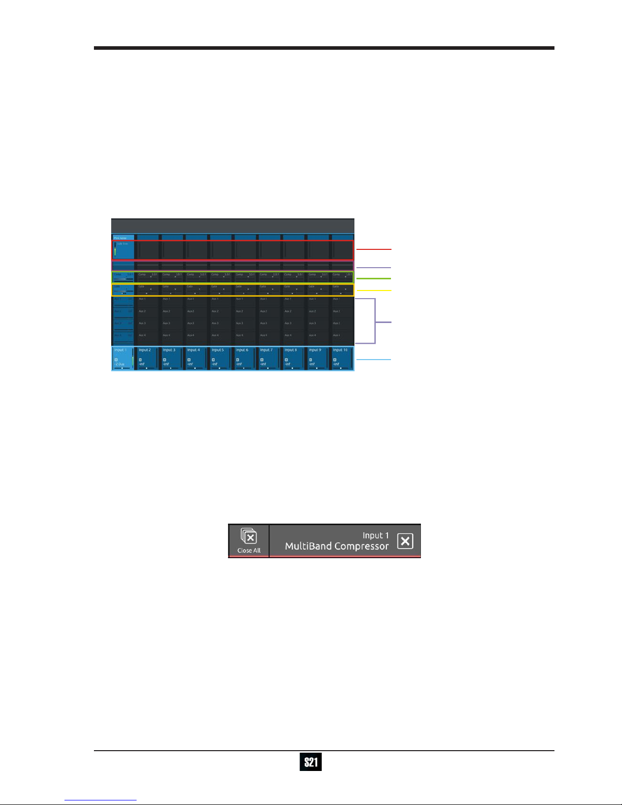
1.2.5 The Under Screen Controls ...................................................
Selected Channel
Blue = Pan - Default assignment
Touch and Hold in this row
Assigns Gain/Trim and highlights in Red
Touch and Hold in this row
Assigns HPF Freq
and highlights in Mauve
and On/Off
Touch and Hold in this row
Assigns Dynamics 1 Threshold and On/Off
and highlights in Green
Touch and Hold any AUX row
Assigns Aux Send & On/Off
Touch and Hold in this row
Assigns Dynamics 2 Threshold
and highlights in Yellow
and On/Off
Touch the selected channel
in this row to return to
default Pan assignment
There is a row of 10 encoder/switches immediately below each touchscreen (shown above) that refer to the channels with which they
are aligned.
1-5
DiGiCo S21
1-5
These controls give access to the channel pans in standard operation and the surrounding coloured LED rings are blue.
Touching and holding on the rows of controls on screen assign these encoders to different parameters, the screen row changes colour
and the LED rings change to a similar colour.
In the above example the Gain/Trim row at the top of the Channel View has been touched, the row is highlighted in red and the under-
screen controls are assigned to the Gain/Trim function.
Other possible assignments are:
HPF Frequency & On/Off - Row and LED ring highlighted in Mauve
Dynamics 1 Threshold & On/Off - Row and LED ring highlighted in Green
Dynamics 2 Threshold & On/Off - Row and LED ring highlighted in Yellow
Selected Aux row Send level & On/Off - Row and LED ring highlighted in Purple
1.3 The Expanded Views
1.3.1 Display Expanded Views .......................................................
A single touch (rather than a touch and hold) will open a number of different expanded views according to where the touch is made.
Opens Channel Setup view
Opens EQ view
Touch any Aux Send to select the channel
and assign the selected Aux Send to the
6th Master Rotary & Aux Pan to the 5th
(with Aux To Faders option OFF)
Swipe vertically to display more Auxes
Opens Dynamics 1 view
Opens Dynamics 2 view
Touch here to select a channel
The image above shows the various touch areas in the Channel view and the expanded view will be displayed on the Master screen.
Note: When an expanded view is already open, selecting a different channel by touching the Output block area at the
bottom of the screen will change the expanded view to display the newly selected channel.
If an expanded view is already open and a different expanded view is selected, the last view selected will be displayed
on the Master screen with the previously expanded view behind it.
Any combination of expanded views can be "layered" in this way.
The Close All button on the Master screen can be touched at any time to close all active expanded views.
The Close button on the Master screen can be touched at any time to close the currently active expanded view and display the view
beneath it.

DiGiCo S21
1-6
1.3.2 Channel Setup View ...............................................................
Channel Name
Column
Title Label
Add To Set
Gain Tracking On/Off
Open Safes View
Select Solo Assignment
Switch to EQ View
Select input source
Filters
Delay
Tubes
EQ
Dyn 1
Dyn 2
Auxes
Direct Out
Groups
Insert A Insert B
Master Rotary
Assignment
Channel Mono/Stereo switch
Touching the input block at the top of the channel opens the Channel Setup view
Each column represents a section of the channel processing strip and these columns can be selected by touching their title label.
Once a column is selected, the parameters available in that section are assigned to the worksurface Master Rotaries to the right of the
screen.
Some columns are subdivided into blocks eg Input processing consists of Filters, Delays and Tubes.
Touching any of these blocks will assign the Master Rotaries to the settings for that block.
Note that touching the Filter block or the EQ block will both display the EQ view but with different bands selected.
Note: When any expanded view is open on the Master screen, the Master Rotaries no longer have their standard de-
fault assignment and are instead assigned to the parameters in the expanded view which is currently displayed.
The buttons in the top bar provide the following functions:
Switching the channel from Mono to Stereo mode
Adding the channel to a Spill Set (see Spill Set section later in this document)
Switching Gain Tracking On/Off for the channel
Opening the Safes View which allows channel parameters to be protected from Snapshot Recall
Selecting which Solo Busses the channels are assigned to
Touch the keyboard icon at the top left of the screen to enter a channel name.
Touch the Equaliser button at the bottom left of the screen to switch to the EQ view for the currently selected channel.
To select an Input Route touch the block below the Source label and the Input routing view will open.
To select an Output Route touch the Direct Output block in the Outputs column and the output routing view will open.
To assign the channel to a Group buss touch the Group Assigns button in the Outputs column
To view and adjust Aux Send Options for the channel touch the relevant Aux Sends button in the Outputs column

1-7
DiGiCo S21
1-7
1.3.3 Group and Aux Setup View....................................................
The Group and Aux Channel Setup view are very similar to the Input Channel version but they have one extra function that is used to
convert a Group Buss to an Aux Buss or vice versa
The S21 has a xed number of output busses but they can be changed at any time to be either Auxes or Groups.
In the example below, touching the Mode button on the Group Setup view will change the Group to an Aux but there is warning that all
channel assignments will be reset in the process. So the newly converted Aux will be attened.
The situation is exactly the same when converting an Aux to a Group - all assignments are reset
Note: In S21 V1.0, Aux/Group Mode can be changed with a Snapshot recall and is part of the Fader, Mute, Mono, CG
member Safe block. Please ensure that the buss modes are set in your rst Snapshot before you create any further
Snapshots. This will ensure that the buss mode settings will be consistent in all Snapshots.
Change Group to Aux
Warning
1.3.4 Input Routing View .................................................................
Touching the Source area on the Channel Setup will open the Input Route expanded view.
Only input channels have a Source selection - output channels sources are xed within the system
To select an input source, touch one of the buttons in the port list on the left of the screen and the relevant sockets will be displayed.
Now touch to select a socket in the socket display.
Inputs can be routed into multiple channels at the same time using the Ripple Route function.
Touch the Ripple Route button in the top bar and then select the rst and last sockets in the required range - then press the OK button.
The Master Rotaries are assigned to the Gain/Trim, +48V and Input Pad controls if they exist for the socket type selected.
Note: Ripple routes are automatically done in the channel display order rather than channel number order.
Select Port
and
Socket Type
Select
Socket
Channel Mono/Stereo switch
Ripple Route
Routing
Details
Master Rotary
Assignment
DiGiCo S21
1-8
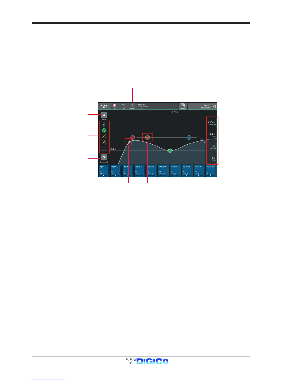
1.3.5 EQ View ...................................................................................
Touching the EQ area on either the Channel view or the Channel Setup will open the EQ expanded view.
The EQ band can be selected by touching the band icons on the left of the screen or by touching the bands on the EQ graph itself.
The graph has 2 modes, 4 band EQ or lters. Touch the relevant band and the adjust the parameters by dragging the band icon on the
graph.
While an EQ band is selected, it can be "pinched" on screen to adjust the Q setting.
The selected band's parameters can also be adjusted with the Master Rotaries to the right of the screen
The buttons in the top bar provide the following functions:
EQ On/Off
Copy EQ to another channel(s) - touch the button and select the destination channels from the channel picker - OK to conrm
Flatten EQ
Switch to Channel Setup
EQ On/Off
Flatten EQ
Switch to Dyn 1 View
Select EQ band
Select EQ Band
Drag to adjust
Select Filters
Drag to adjust
Master Rotary
Assignment
Copy EQ
1-9
DiGiCo S21
1-9
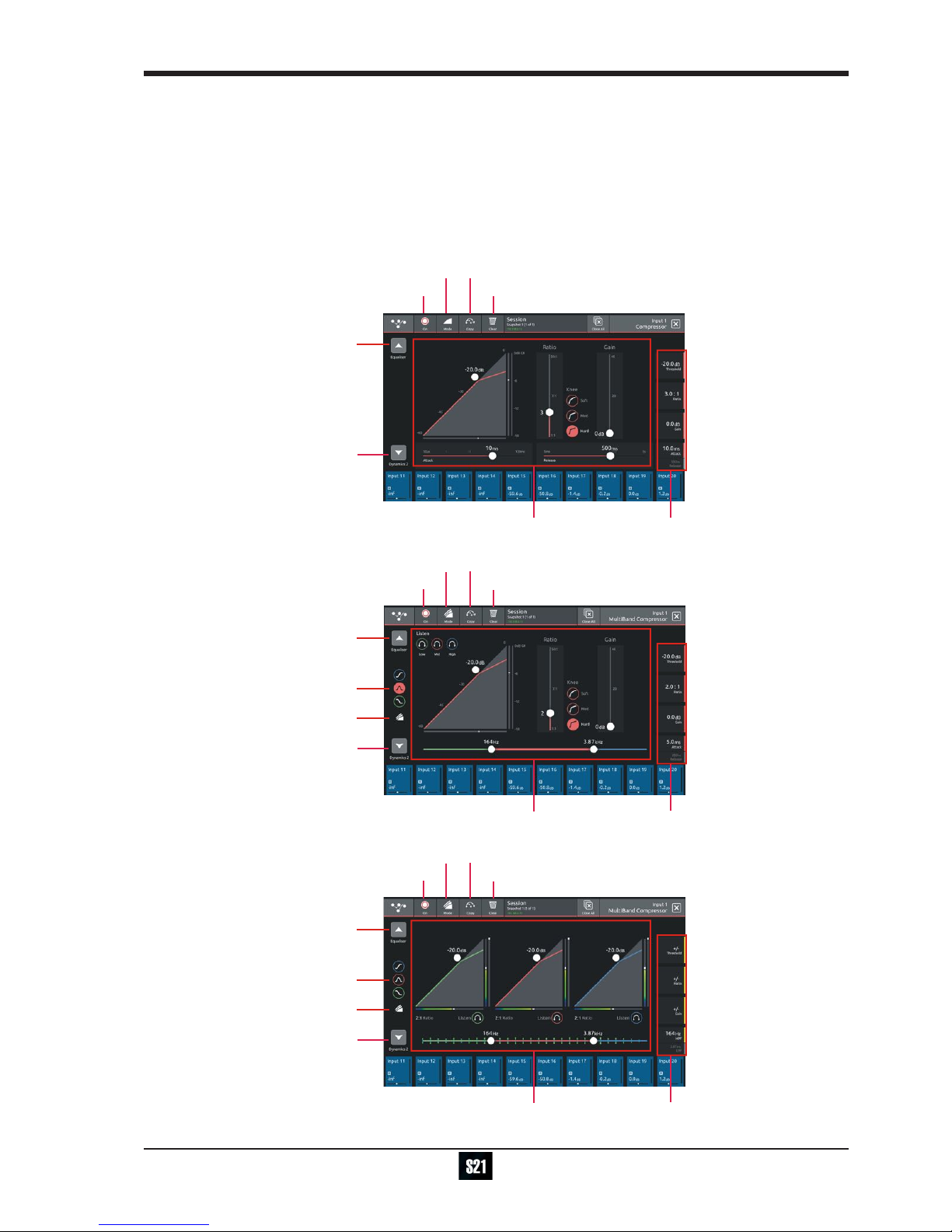
1.3.6 Dynamics 1 View ....................................................................
Touching the Dynamics 1 area on either the Channel view or the Channel Setup will open the Dynamics 1 expanded view.
Dynamics 1 can be a Single Band or Multiband Compressor (on 4 channels). Touch the Mode button in the top bar to switch modes.
Multiband Dynamics has 4 viewing modes, one for each individual band and one that displays all 3 bands at the same time. These are
selected with the buttons on the left of the screen.
Parameters can be adjusted on-screen or using the Master Rotaries to the right of the screen.
The buttons in the top bar also provide the following functions:
Dynamics Module On/Off
Copy Dynamics settings to another channel(s) - touch the button and select the destination channels from the channel picker - OK to
conrm
Reset Dynamics module
Switch to EQ view
DYN 1 On/Off Reset DYN 1
Copy DYN 1
Switch to Dyn 2 view
Adjust
Parameters
Master Rotary
Assignment
Select Mode
Switch to EQ view
Select band
MultiBand view
DYN 1 On/Off Reset DYN 1
Copy DYN 1
Switch to Dyn 2 view
Adjust
Parameters
Master Rotary
Assignment
Select Mode
Switch to EQ view
Select band
MultiBand view
DYN 1 On/Off Reset DYN 1
Copy DYN 1
Switch to Dyn 2 view
Adjust
Parameters
Master Rotary
Assignment
Select Mode
DiGiCo S21
1-10
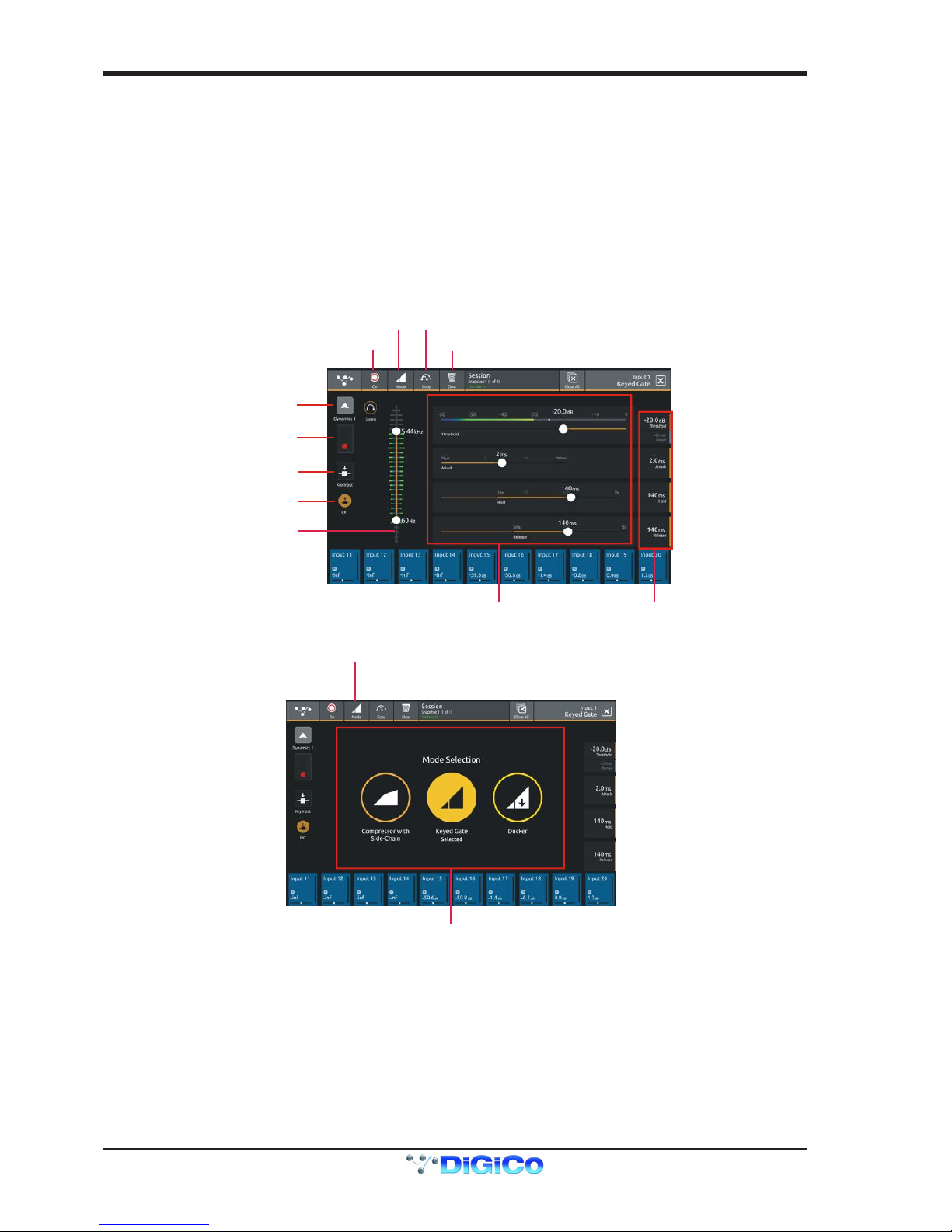
1.3.7 Dynamics 2 View ....................................................................
Touching the Dynamics 2 area on either the Channel view or the Channel Setup will open the Dynamics 2 expanded view.
Dynamics 2 can be a Keyed Gate, a Ducker or Single Band Compressor with Side Chain.
Touch the Mode button in the top bar to switch modes.
Dynamics module 2 provides side chain access via a selectable input - this can be used for external triggering.
Select the Source signal by touching the Key/Side Chain input button on the left of the screen and select a source from the standard
input routing list.Then use the Self/Ext button to activate this function.
Parameters can be adjusted on-screen or using the Master Rotaries to the right of the screen.
The buttons in the top bar also provide the following functions:
Dynamics Module On/Off
Copy Dynamics settings to another channel(s) - touch the button and select the destination channels from the channel picker - OK to
conrm
Reset Dynamics module
Switch to DYN 1 view
Gate status
Select Key Source
Key Input On/Off
DYN 2 On/Off Reset DYN 2
Copy DYN 2
Meter and Key Filter
Adjust
Parameters
Master Rotary
Assignment
Select Mode
Select DYN 2 Mode
Select Mode
1-11
DiGiCo S21
1-11
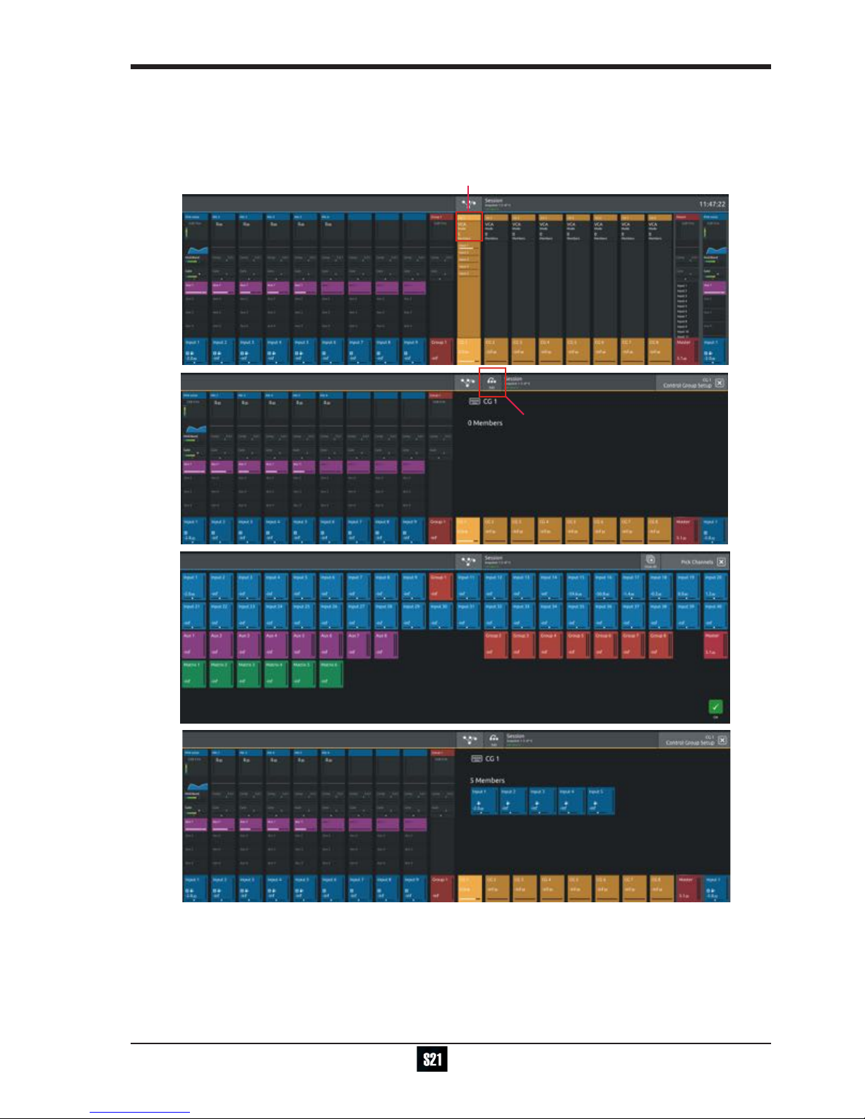
1.3.8 Control Group Setup ..............................................................
To create a Control Group, touch the top of a Control Group Channel to open the CG Setup view
Touch the Edit button in the top bar
Select the required CG members by touching them in the Channel Picker and touch the OK button
The CG Setup view will now show blocks representing each of the CG members and the CG channel will display a list of its members
with their fader levels
Setup CG
Edit CG
Select CG Members and Touch OK
Warning
DiGiCo S21
1-12
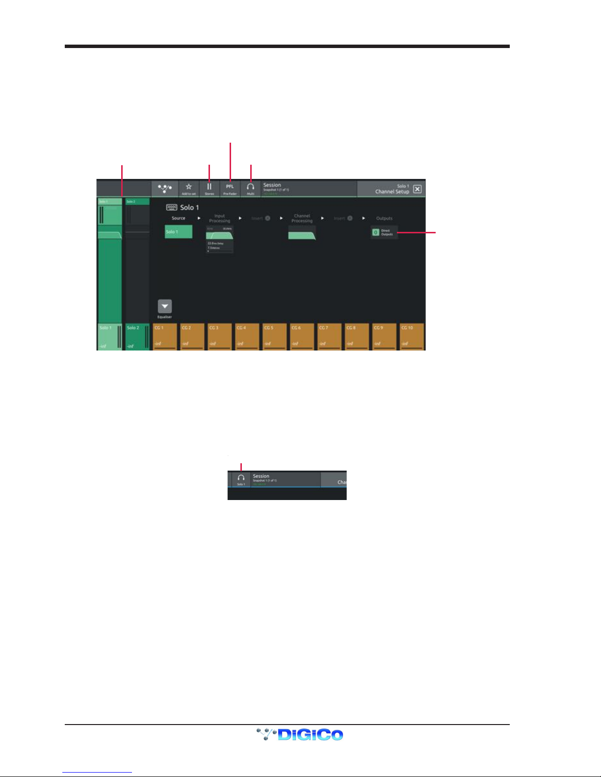
1.3.9 Solo Channel Setup................................................................
The S21 has 2 Solo busses which have their own control channels in the console layout normally located on the 4th layer next to the
Matrix Output channels.
Note: Both Solo busses 1&2 are both sent permanently to the console headphone socket.
When no channels are soloed, the Master Buss (No Solo source) will always be sent to Solo Buss 1
Route Solo
Direct Out
Solo
Channels
Stereo
Mono
Switch
Multi/Single
Mode
PFL/AFL
Mode
Touching the top of either Solo channel will open the relevant Solo setup view
Various Solo buss settings can be found in the top bar of this view
Solo busses can be switched Mono or Stereo
They can be set to PFL or AFL mode
They can be set to Multi Mode where multiple solos can be switched on at the same time or Single Mode where switching one solo on
will cancel previously active Solos
Any channel can be assigned to Solo Buss 1, 2 or both 1&2.
Open the channel setup view for any channel and there is a Solo buss assignment button in the top bar.
Channel Name
Column
Title Label
Add To Set
Gain Tracking On/Off
Open Safes View
Select Solo Assignment
Switch to EQ View
Select input source
Filters
Delay
Tubes
EQ
Dyn 1
Dyn 2
Auxes
Direct Out
Groups
Insert A Insert B
Master Rotary
Assignment
Channel Mono/Stereo switch
1-13
DiGiCo S21
1-13
1.4 Customising the Layout
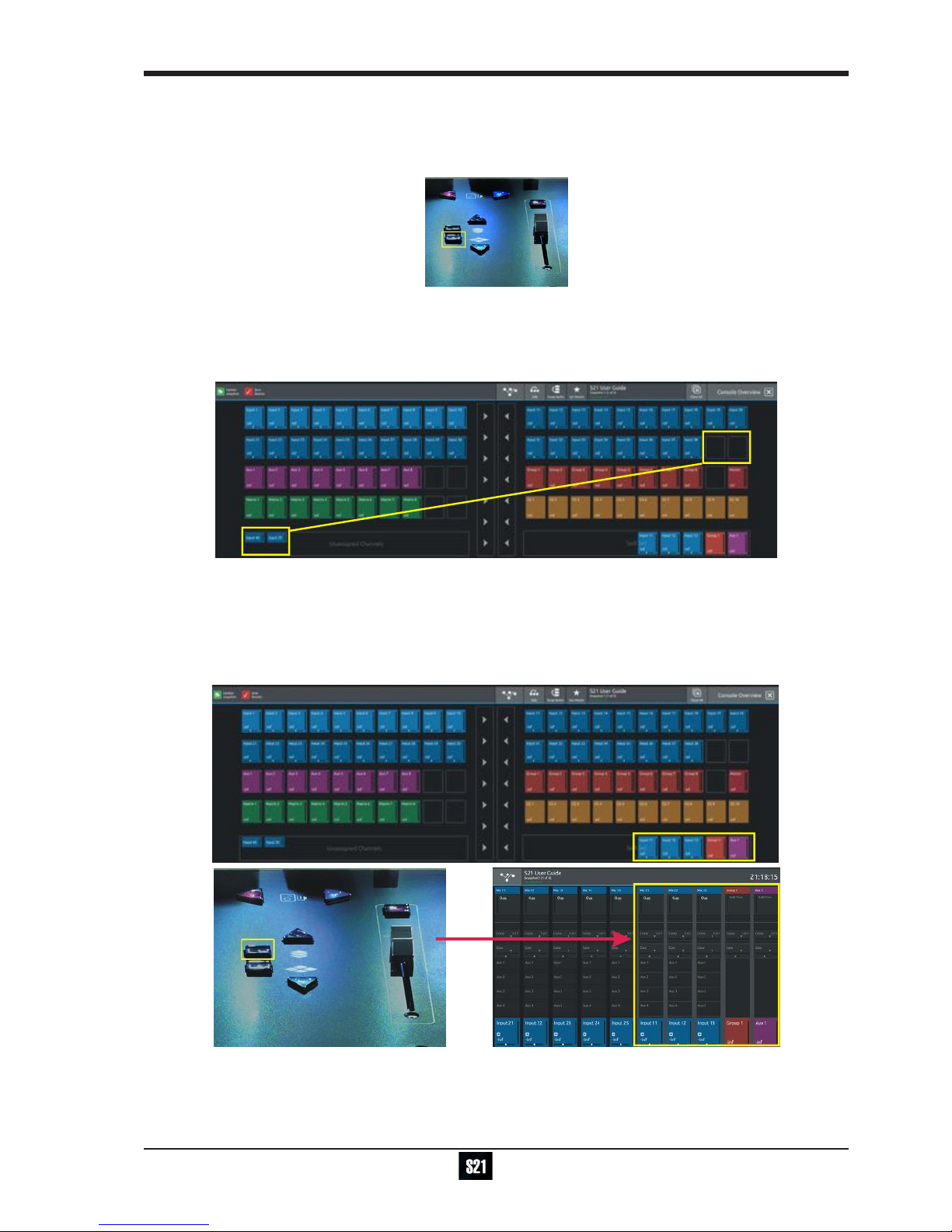
1.4.1 The Console Overview ..........................................................
Pressing the white Overview button, located near the layer up and down buttons displays an on screen representation of all console
channels. This view can be used to change the layout of the console channels and banks.
Touching the Edit button in the top bar changes the appearance of the display and activates drag and drop capability.
Any block that represents a channel can be dragged to another position and dropped there. This will overwrite the channel in that posi-
tion and the overwritten channel will reappear in the Unassigned Channels section at the bottom of the left screen.
Channel blocks can also be dragged directly to the Unassigned Channels section to remove them from the worksurface
Note: Channel blocks can be dragged between the 2 console screens
1.4.2 The Spill Set ...........................................................................
In Edit mode, a selection of up to 10 channels can be dragged to the Spill Set section at the bottom of the right hand overview screen to
create a Spill Set.
Typically, these would be channels to which the user needs to have quick access at all times.
When a Spill Set has been created, the worksurface button located above the overview button will become blue and pressing this button
will display the Spill Set channels on the right hand screen. pressing again hides the Spill Set.

DiGiCo S21
1-14
1.4.3 Swap Banks ...........................................................................
In Edit mode, touching the Swap Banks button in the top bar allows complete banks to be moved from one position to another either
from left to right or from one layer to another.
Swap Banks
1.4.4 Set Master ..............................................................................
In Edit mode, touching the Set Master button in the top bar allows a bank to be selected that will be locked to the right hand console
screen. press the Set Master button and then touch the required bank.
In this mode, all other banks are assigned to the left hand console screen and can be accessed using the worksurface layer up and
down buttons. Once a Master is set, it can be cleared by touching the Clear Master button in the top bar.
Set Master / Clear Master
1-15
DiGiCo S21
1-15
1.5 The Main Menu
The right hand Master Screen has a DiGiCo logo icon at the top which is used to open the Main Menu
The Main Menu contains a number of buttons which are used to access various console functions
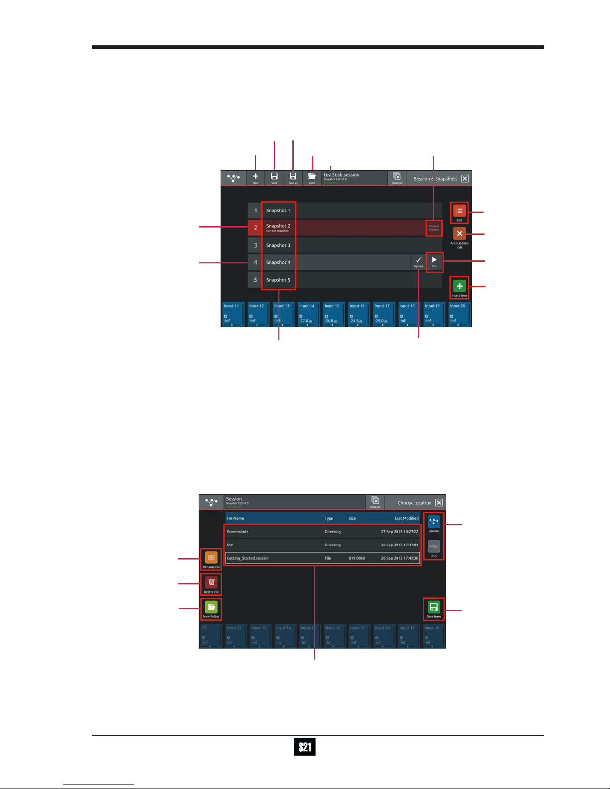
1.5.1 Session Management .............................................................
Touching the Sessions & Snapshots button opens a display which contains le management functions in the top bar and Snapshot
control in the main area of the screen.
Session Name
Create New Session
Save As New File
Load Session
Snapshot
Auto Update
Edit Mode
Current Snapshot - Red
Selected Snapshot - Grey
Snapshot
Name
Fire
Button
Update
Snapshot
Snapshot has
unsaved changes
Insert New
Snapshot
Save Session
To create a new session, touch the New button in the top bar and a progress bar will be displayed.
When the process is complete, touch the Save As button, select the internal drive (labelled Home) or the USB port (with a USB key
inserted into the console USB port) and touch the Save Here button.
Then type a new session name using the on-screen keyboard and touch the Done button.
To update the session after the initial Save As process, just touch the Save button and the current session will be updated automatically.
To load an existing session, touch the Load button, select the internal or USB drive and then select the required session from the list
and touch the OK button.
NOTE: The Auto-Update button on the left of the screen relates to Snapshots and not to Sessions
When active, this function will automatically update the current Snapshot as changes are made on the console.
Please read the Snapshot section and only activate this function if you denitely require it.
Select
Internal
or USB
Touc h
Save Here
to enter a
new name
Create New
Folder
Delete
File
Rename
File
Existing session and folder list

DiGiCo S21
1-16
1.5.2 Snapshots ...............................................................................
The S21 always has at least one Snapshot in its list and more can be added using the Insert New button in the bottom right corner of
the screen. The Current Snapshot is highlighted in red.
We recommend that the rst snapshot is used as a "Setup" Snapshot where all of your "session wide" settings like routing, Control
Group membership and Buss Modes (whether Busses are Groups or Auxes) are rst stored.
Because these types of setting can be changed with Snapshot recall, it is advisable to save them all into this rst snapshot before creat-
ing any further Snapshots. In this way, the settings for all subsequent Snapshots will contain the same data and there should be less
requirement to adjust the Safe settings in the channels.
When a Snapshot is created it will always save all of the current console settings and it will be placed in the Snapshot list after the Se-
lected (highlighted in light grey) Snapshot.
Subsequently, certain console parameters can be isolated or made "Safe" from Snapshot Recall as required.
To recall (Fire) a different Snapshot, it must rst be selected on the list, highlighting it in light grey, and then the Fire button should be
touched.
The Previous and Next Snapshots in the list can also be red by pressing the Prev/Next buttons on the worksurface.
When the console state has changed but the current Snapshot has not been updated, the Snapshot will be marked as having "Unused
changes". Pressing the update button on the current Snapshot will store these unused changes.
To change a Snapshot name touch the Edit button at the top of the list, touch the Snapshot name and type using the on-screen key-
board.
To delete a Snapshot, touch the Edit button (if not already active) and then touch the Delete button (dustbin icon) next to the required
Snapshot. You will then be required to conrm the action by touching the Yes button.
To rename a Snapshot, touch the Edit button (if not already active) and then touch the Rename button next to the required Snapshot.
You will then be required to enter a new name and conrm
Exit
Edit
Mode
Delete
Snapshot
Rename
Snapshot
Table of contents
Other digico Dj Equipment manuals


Popular Dj Equipment manuals by other brands


Scanic
Scanic SkyFlower 2500 instruction manual

JB Systems
JB Systems SPACE-4 Mk2 LASER Operation manual

JB Systems
JB Systems Liverack-10 Operation manual

involight
involight BM300 user manual

Lightwave Research
Lightwave Research High End Systems Studio 250 Series user manual

Osram
Osram CLAYPAKY ALPHA WASH 1500 instruction manual