DIGISYNTHETIC DS212 User manual

DIGISYNTHETIC PRO
24-BIT DUAL ENGINE AUTOMATIC FEEDBACK DESTROYER/PARAMETER EQ MODEL DS212
Instruction Manual
24 BIT DIGITAL PROCESSOR
FEEDBACK EXTERMINATOR
L
R
CLIP
CLIP
FILTER SEL
BYPASS
FILTER MODE STORE
MIDI
CH L
CH R
COUPLE
FEEDBACK
EXTERMINATOR
POWER
DIGISYNTHETIC
DS
212
PARAM/PUSH

Page 1
ATTENTION!
All DIGISYNTHETIC PRO products are carefully packed and designed to protect the units from rough handl
-ing before shipping out from the factory. Examine your good upon receiving, to ensure no damage during
transportation. Any damage claim should be inform & notify to relative dealer within 14 days of good received.
The dealer will not except failing of such. The consignee must make all shipping claims.
The DS212 fits into a standard 19" rack unit of space (1 3/4"). Allow at least an additional 4" depth for the
connectors on the back panel. Be sure that there is enough air space around the unit for cooling and ventilation.
DO NOT place the DS212 on high temperature devices like power amplifiers etc. to avoid overheating.
Using a main cable and a standard IEC receptacle makes the main connection of the DS212. It meets all of the
international safety certification requirements.
Please make sure that all units have a proper ground connection. For your own safety, do not remove the ground
connection within the unit or at the supply, or fail to make this connection at all.
Before switching voltage for local supply requirement, correct fuse type and rate must be installed. Refer to
4.Appendix.
This machine is only intended for qualified personnel to operate & install. Do not attempt to repair and service
yourself but referred to qualified technical service personnel. The user must have sufficient electrical contact
to earth. Electrostatic charges might affect the operation of the DS212.

DIGISYNTHETIC PRO MODE DS212
Page 2
7
7
7
7
7
7
7
7
7
7
7
7
7
7
7
64/128 time over-sampling for ultra-high resolution, 24-bit A/D & D/A converter, precise analysis
12 auto detect feedback frequencies in every channel, intelligent management
24 types of editable parametric EQ by either manual or MIDI connection
, complete feedback compress function
Single preset & auto mode control & Lockable filter until manual adjust or reset
Manual function able to set 2x12 parameters of filter inclusive of frequency, bandwidth, gain, etc.
Servo balance input & output, gold plated XLR & TRS connectors
3 modes for every filter function: SINGLE, AUTO & MANUAL
Left & Right channel is able to work individually or combination by dual modular processor
High quality 24-bit processor ensures effective signal transmission
Soft touch with relay ON/OFF switch, gate noise function
2x16 character back light LCD display screen
Full MIDI capability allows real time controlling with USER program memory
High quality components and exceptionally rugged construction ensures durability
Internal power supply design for professional application
Convenient setting enables immediate
24 BIT DIGITAL PROCESSOR
FEEDBACK EXTERMINATOR
L
R
CLIP
CLIP
FILTERSEL
BYPASS
FILTERMODE STORE
MIDI
CH L
CH R
COUPLE
FEEDBACK
EXTERMINATOR
POWER
DIGISYNTHETIC
DS
212
PARAM/PUSH

Page 3
TABLE OF CONTENTS
1. Introduction
2. Control Panel
2.1 Menu Function Illustration
2.2 Function Buttons & Jog Wheel
2.3 Combination Key & Button
2.4 Rear Panel
3. Function & Feature instruction
3.1 Enable & Disable Filter mode
3.2 Filter/Parametric EQ Menu
3.3 Auto mode Filter
3.4 Sequence Select
3.4.1 Sequence Adjust
3.4.2 Preset mode Select
3.4.3 Filter parameter Adjust
3.4.4 Store & Memory Sequence
3.5 MIDI control
4. Appendix
4.1 Frequency Chart List
4.2 Preset Chart List
4.3 Technical Specifications

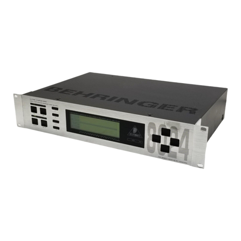
There are 6 function buttons for control & editing purpose and 1 LCD display screen in the DS212 Front panel.
2.1 Menu display & functions
Fig 2.1 Front PanelDS212
P 1 CH L EQ-ON
FILE 3 PEQ SV
L
R
CLIP
CLIP
Fig 2.2 Menu selection
(1) 2
"P:"
LED light for left/right input/output indication.
(2) indicates menu sequence select. Select any sequence from 0~10 by blinking ":" symbol with rotary
jog wheel.
Page 4
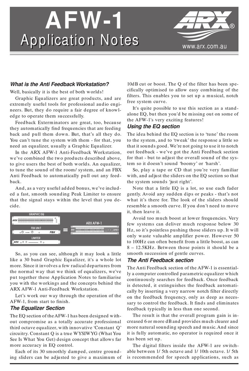
1. Introduction
DS212 is a cost-effective machine with auto digital feedback destroyer. It can store up to 10 groups of data,
and meet 10 different environmental requirements tone control. It increases signal output from +16dB~48dB.
When feedback occurs, DS212 will analyze through DSP calculation and auto detect & destroy feedback
frequencies. Then stores all result to memory. As DS212 only control & destroy the decay of filter bandwidth
It only eliminates the feedback signals and does not affect the music signal with high definition.
(1) Adjustable Filter frequency bandwidth
While in compressing feedback, filter frequency bandwidth is fluctuating and adjustable from 2 times frequency
range to 1/60. This compresses feedback effectively.
(2) Adjustable compression Threshold
User can adjust the Threshold of DS212 to initial feedback filtering in different excited level from -3dB to
-9dB.
(3) Displays all parameters
LCD screen with back light to display all filtering parameters in AUTO or SINGLE mode entering parametric
EQ manual, e.g.: you are able to read the feedback frequencies, frequency bandwidth & decreasing values. User
Is able to make changes from all this data through LCD screen.
(4) Act as Parametric EQ
There are 12 filter in every channel of DS212. In normal situation, feedback sound will not be more than
3 or 4 frequencies, thus the remainder ones are not been use and can be uterlise as parametric EQ for adju
-sting room acoustic & to compensate lost frequencies.
2.Control Front Panel
24 BIT DIGITAL PROCESSOR
FEEDBACK EXTERMINATOR
L
R
CLIP
CLIP
FILTERSEL
BYPASS
FILTERMODE STORE
MIDI
CH L
CH R
COUPLE
FEEDBACK
EXTERMINATOR
POWER
DIGISYNTHETIC
DS
212
PARAM/PUSH

0
I
FILTER SET CHL IN/OUT
FILTER MODE
COUPLE
STORE
MIDI
CHR
PARAM/PUSH
0
I
Fig 2.3 Function Buttons & jog wheel
(1) PARAM/PUSH- Rotary Jog wheel with ON/OFF ability. While selecting "PEQ" in filter mode, press jog
wheel to enter parametric EQ editing (as fig.2.4).
P 1 CH L EQ-ON
FILE 3 PEQ SV
L
R
CLIP
CLIP
Page 5
(3) "CH:" -- Adjustable Left/Right channel menu display. "CH: L" & "CH: R" indicate able to edit left & right
channel respectively. "CH: LR" means left & right channel is able to edit at the same time.
(4) "EQ" -- When this symbol is seen to indicate "EQ-ON". To on all filter: "EQ-OF", Auto & Single not affected,
"BYPA." -- BYPASS mode, all filter effect is not functioning.
(5) "FILT:"-- Able to select any filter from 1~12 by jog wheel when ":" blinks.
(6) ":PEQ"-- Turning rotary jog wheel while ":" blinking to select 4 types of filter mode from: OFF (off), PEQ
(parametric EQ), AUTO(automatic) & SING(single).
(7) To edit parameters of filter and parametric EQ. LCD reads "SV" to remind user that editable parameters is
ready for save & memory by 2 seconds blinking interval. Press "STORE" button once and it will blinkslow
for 1 second interval to remind user whether to save or not. Presses "STORE" button one time to savefast
and "SV" will disappear to indicate edited parameters had been save in present sequence. (If user does not
press "STORE" while "SV" blinking within 10 times, it will go back to blink)fast slow
2.2 Function Buttons & Jog Wheel
FEEDBACK DESTROYER
24 BIT DIGITAL PROCESSOR
Fig 2.4 Parametric EQ menu
FREQ: To select desire frequency
GAIN: To increase or decrease values for selected filter
BAND: To decide frequency band for selected filter, adjustable values from 2-time frequency range (120/60-
octave range) to 1/60 octave range.
(2) FILTER SEL- Sequence & Filter Select Button. Available 12 Filters or 10 channels. Press once to enter
Filter, press second times to enter sequence selects.
(3) FILTER MODE- Filter Mode Select Button. Press this button and turn jog wheel to activate "OFF" (off),
"PEQ" (parametric EQ), "SING" (single) & "AUTO" (automatic) modes. Press FILTER MODE & PARAM
/PUSH button together for 1 second, you are able to adjust Threshold of feedback compression from -3~-9dB.
(4) CHL, (5) CHR- Left and Right channel parameters button enable left & right channel editing. Press CHL
& CHR button to activate left & right channel function. Press left channel button "CHL" before pressing
"CHR" button to copy left channel parameters to right channel.
(6) IN/OUT (input/output) Button- allows optional bypassing of the parametric equalizer or all filters.
(7) STORE Button- Any preset parameters can be edited by STORE button. (Remarks: Press twice to store
data and symbol "SV" will disappear.)
POWER

OUTPUTS 2
INPUT LEVEL INPUT LEVEL
OUTPUTS 2INPUTS 2 INPUTS 1
SERIAL NUMBER
DATE CODE
(1) INPUT LEVEL ADJUSTER: From -20dB ~ +4dB
(2) ANALOG INPUT: XLR or TRS input socket, Parallel between XLR & TRS input. Balance & Unbalance
configuration.
(3) ANALOG OUTPUT : XLR or TRS output socket, Parallel between XLR & TRS input. Balance & Unba
-lance configuration.
(4) MIDI OUT/THROUGH/IN : Able for total Remote Control via MIDI Channel.
(5) MAIN CONNECTOR/FUSE HOLDER/VOLTAGE SELECTOR: Before you connect the unit, please
make sure that the displayed voltage corresponds to your Mains supply, Please note that the AC voltage
selection is defined by the position of the Fuse Holder. If you intend to change the two markers monitors
the selected voltage, Please note that, depending on the mains voltage supplied to the unit, the correct fuse
type and rate must be installed (see 4.3 Technical Specifications). Please use the enclosed main cable to
connect the unit to the mains power supply.
3. Function Descriptions
DS212 is able to work with 4 different modes. In order to meet flexible & complicated signal processing,
you may combine all the 4 modes in one sequence.
3.1 Activate & Cancel Filter mode
During "OFF" mode, Filter will be cancel able to activate by below selection:
3.2 Manual Filter/Parametric EQ
DS212 is able to process any musical signal. To increase or decrease fix frequency level, you may use manual
filter to select all these frequencies (parametric EQ mode). Every filter is able to set central frequency, octave
band (1/60) & increase/decrease value (in dB).
3.3 Auto Filter
The AUTO Filter will work with 2 types of modes: SINGLE & AUTO mode. In order to sense feedback,
DS212 will divide the entire frequency bandwidth 1/60 octave steps (20Hz~20kHz) and decide on this
Frequency band responsive level, evaluate and comparing this value & the entire signal level, thus the Different
Value in signal level will determine whether to activate filter or not. You may change the feedback sensitivity
From -3dB ~ -9dB (in 1dB Steps). The standard value is -6dB and is applicable in most of the feedback
Page 6
2.3 Combination Buttons
(1) Hold CHL or CHR button (do not release), and press another button to disable Left & Right channel adjus
-tment at the same time.
(2) Press FILTER MODE & PARAM/PUSH button to adjust Threshold of feedback destroyer.
(3) Press STORE & IN/OUT button to enter MIDI control menu.
(4) Press FILTER SEL & STORE button then on power supply to display "RESET". System is reset to original
factory default status.
2.4 Rear Panel
FUSE:
220VAC :10%
ATTENTION:

Display Operation Modes
OFF Disable
PEQ Parametric EQ
AUTO Automatic
SING Single
LOCK Lock
Page 7
Reconization & situation. In solely speech transmission, you may lower the feedback sensitivity to -9dB.
This will compress feedback speedily. On the other hand, increase in feedback sensitivity (e.g. -3dB) will be
More stabilize, but will be slower in detecting the feedback signal.
SINGLE mode in filtering process will analyze music signal automatically in order to detect feedback
frequencies. Once detected the feedback frequencies, filter will set its parameters to compress feedback
automatically. As filter is lock on detected feedback frequencies, thus these types of mode are very suitable
for compressing feedback with constant frequency. Effective application such as fixed located microphone
(e.g. inside a permanent installed conference room system). Although Filter will adjust automatically and
enter to a lock mode to fix the frequencies, but the octave band and depth of filter are still effective for
feedback frequencies. Once feedback frequencies move, there will be an increase in octave band range
resulting feedback in preference and decrease in gain till feedback repeated.
All moveable microphones are advice to work with AUTO mode for feedback control as they always have
changeable feedback frequencies. Under AUTO mode operation, filter will follow & compress feedback
frequencies even frequencies moved about. Filter will set its parameter as narrow band as possible and not
to affect musical signal.
3.4 Sequence Select
In order to store and save your favorable preset, DS212 consist of 10 USER program preset sequence and
shortcut preset sequence. All operated parameters are able to store in shortcut sequence manual for user to
select desire program. All data is good for 20 years and above storage memory. In shortcut preset (display
"0". It acts as user's basic sequence, NOT user's memory channel), all filter maintain at its parameter mode,
octave band will set at 1 time frequency range, frequency as 500Hz and 0dB gain.
3.4.1 Adjusting Sequence
After power is on, DS212 will display previously used preset value. Turning jog wheel to select your
desire preset value.
3.4.2 Program Sequence Select
Fig. 3.1 Displays all Filter mode program.
Fig.3.1 DS212 Filter Operation Modes
To alter filter mode: First, press FIL SEL (filter select) button and select filter from 1~12 by jog wheel. Use
CH (channel select) button not only to select left right channel but also selection of both left right channel.or and
Then press FILTER MODE (filter mode) button and turn rotary jog wheel to select filter mode.
If "LOCK" displays to indicate there is a filter from SINGLE mode already in processing with feedback situation.
You are not able to release this filtration by going back to SINGLE mode. Once discover new feedback point,
DS212 will immediately shirt the previous filter frequency to a new one. If you escape from AUTO & SINGLE
mode and entering parameter mode, filter will remain all parameters that have been set.
3.4.3 Adjusting Filter parameter
In order to adjust Filter setting, it must be set inside parametric EQ mode. Press jog wheel to select FREQ
(frequency) menu, turn jog wheel to select desire ISO frequency. In FINE (fine) Manual, user is able to
fine tune selected ISO frequency (in1/60-octave steps) within 1/3 octave band to display mathematics ratio
between value & confirmed frequency, and detect desire frequency speedily. At this moment, user may
adjust filter octave band from 2 times frequency range to 1/60 times frequency range by selecting BAND

Display Modes
CONTROL0 No controller data are transmitted
CONTROL1 Controller data are received but not transmitted
CONTROL2 Controller data are transmitted but not received
CONTROL3 Controller data are transmitted and received
CONTROL4 Similar to 3 with Filter sequence no
Page 8
(band). Select GAIN (gain) Menu to increase or decrease desire dB gain in selected frequency. "+" Means
increase in level and "-" means decrease. During SINGLE & AUTO mode, you are not able to edit any
Filter parameter. You are only able to adjust Filter parameter in these modes for similar filter frequency
and octave band with 0dB gain. Simply press FILTER MODE button and hold for 2 seconds to re start a
lock Filter by selecting SINGLE or AUTO mode.
3.4.4 Store Sequence
Use STORE button to activate store sequence. Basically, all edited parameter in parametric EQ mode is
able to store & save. Filter will adjust automatically and save required data under SINGLE & AUTO mode
operation. E.g.:
To edit a sequence by function button & jog wheel. LCD displays 2 seconds interval blinking "SV" (save)
symbol, this is to indicate preset has been edited but not been save yet. Press FILTER SEL button to enter
sequence select channel manual, press STORE button once and "SV" symbol will blink fast in 1-second
interval. In order to maintain original setting, you may use jog wheel to select an editable different preset
channel no. Press STORE button again, "SV" symbol will disappear and save data in the selected preset
store channel no. If user wish to change original preset, simply press STORE button twice after editing
to store all the changes.
Remarks: When you change a preset and press STORE button twice, then all the data before this preset
will be void and only new parameter will be rewrite. But if you wish to keep previous setting, then you
have to select another preset store channel no (by jog wheel) before you press STORE button second time.
3.5 MIDI control
Use the MIDI key combination to select the MIDI parameters you wish to adjust. For this purpose press and
keep the IN/OUT and the STORE buttons. All parameters can be edited with the jog wheel and the IN /OUT
button. The MIDI menu includes 6 pages, which you can select by pressing the IN/OUT button several times.
In page 1, you are able to select MIDI channel as display "CH-XX" in screen. User is able to select channel
from OFF to 1 through 16 by jog wheel. To disable MIDI function, simply select "OFF".
You are able to select full MIDI mode in 2 page. This means the unit transmits/receives on all 16 MIDI
nd
channels. "Omni" will display in screen and by turning jog wheel to "ON" or "OFF" to enable or disable
all function modes.
User is able to configure controller commands in the 3 page. "CONTROLX" will display in screen and jog
rd
wheel selects one of the following 4 controller modes:
Fig.3.2 Controller Settings
When you select controller 4, you may select different menus from frequency, gain, fine tune frequency.
DS212 will send auto filter parameter.
The fourth page gives you access to the program change setup. The display reads "ProgramX", here, too.
Four modes can be selected with the jog wheel, as follows:

Page 9
Display Modes
Program0 Program changes are not transmitted
Program1 Program changes are received but not transmitted
Program2 Program changes are transmitted but not received
Program3 Program changes are transmitted and received
Fig.3.3 Program change settings
The fifth page of the MIDI menu shows the "SAVE" symbol in the display. The "SAVE OFF" disable the
reception of controller #28, and therefore protects the user presets from being modified via MIDI.
Accordingly, the "SAVE ON " value enables MIDI controller #28 so that you can modify or replace presets
with a remote MIDI device or a sequencer. In this case the actual settings will be stored directly to the location
that corresponds to the controller value.
ATTENTION! Since the "store enable" mode allows you to access memory locations directly via MIDI,
it is possible that stored presets will be replaced or altered if controller #28 messages are sent on the
same MIDI channel. The purpose of this mode is to facilitate MIDI backup and restore operations
without express conformation at the DS212. It is therefore recommended to disable "SAVE OFF"
mode as soon as the intended data transfer has ended. This is done automatically when you switch
off the DS212.
On the sixth, and presently the last, page you can access the "System Exclusive"(SYSEX) functions. This
is indicated by a "d" (for dump) in the display.
means that no SYSEX data will be sent or accepted.-SYS OFF
will enable the DS212 to receive data. When STORE is pressed the unit will wait for data; this-SYS RXD
is shown by "RXD" flashing.
will enable the DS212 to send a "bulk dump". Start your sequencer and press STORE on the-SYS TXD
DS212 to start the transmission. OFF will display when transmission is completed.
During a bulk dump, all audio functions of the DS212 will be deactivated.
To load these settings again, press STORE and start your sequencer, If your press IN/OUT button again,
you will leave the MIDI setup. You can at all times press any other key to leave the MIDI setup directly.
DS212 has total command of MIDI ability and able to combine & work with any MIDI system.
MIDI IN
Any MIDI data sent to the DS212 (sequencer, MIDI footswitch, etc) are received via the MIDI IN jack.
For example, when you wish to use the DS212 as an effects devices for our guitar rack, you can connect
the MIDI IN jack to a MIDI footswitch that allows for selecting program presets. If your rack includes an
-other MIDI effects devices (e.g. a multi-effects processor), the data sent from the MIDI footswitch can be
routed via the DS212 MIDI THRU jack to your multi-effects processor.
MIDI THRU
The MIDI THRU jack is used to loop through incoming MIDI data; i.e. any control received at the MIDI
IN of the DS212 can be transmitted via MIDI THRU jack to other MIDI devices or instruments.
MIDI OUT
The MIDI OUT jack allows for transmitting MIDI data that originate from the DS212.

4.Appendix
4.1 Frequency data chart
Display Display
Page 10

4.2 Preset table
Preset Filter 1 Filter 2 Filter 3 Filter 4 Filter 5 Filter 6 Filter 7 Filter 8 Filter 9 Filter 10 Filter 11 Filter 12
1 MONO:9 single shot filters attenuate room resonance before 3 automatic filters destroy variable feedbacks
Left
Right
2 2xMONITOR AS FEEDBACK DESTROYER ONLY:7 single shots/5 automatic filters for most monitor setup
Left
Right
3 MONO AUTO PILOT:12 filters per channel constantly chase and destroy feedbacks
Left AUTO AUTO AUTO AUTO AUTO AUTO AUTO AUTO AUTO AUTO AUTO AUTO
Right
4 STEREO PARAMETRIC EQ:Preset with 12 ISO frequencies, all set to 1/3 octave,gain +0dB
Couple
5 STEREO PARAMETRIC EQ:Preset with 12 ISO frequencies,all set to 2/3 octave,gain +0dB
Couple
6 23MONO:Sample monitoring,left for handheld(lead)microphone(s),right for fixed(backing)ones
Left
Right
7 MONO PARAMETRI AND SINGLE SHOT FILTERS: A good start for fixed(backing)ones
Left
Right
8 STEREO FOH EQ:providing 4 parametric EQ (low roll in filter and 2),plus 8 single shot filters
Channels coupled,changes onone channel are valid for both.
MONO FREE
Left
Right
STEREO FREE
Couple
Page 11

4.3 Specifications
Analog Inputs
Connectors XLR and 1/4" jack
Type RF filtered, servo balanced , 20kOhms unbalanced
Impedance 40kOhms balanced, 20kOhms unbalanced
Nominal Operating Level -20dB to +4dB
Max. Input Level +16dB at +4dB nominal level, +2dB at -20dB nominal level
Analog Outputs
Connectors XLR and 1/4" jack
Type Electronically servo-balanced output stage
Impedance 66Ohms balanced, 33Ohms unbalanced
Max. Output Level +16dB at +4dB nominal level, +2dB at -20dB nominal level
System specifications
Bandwidth 20Hz to 20KHz
S/N 98dB, weighted, 20Hz to 20KHz
THD 0.065%typ. @+4dB, 1KHz, Gain 1
Crosstalk -95dB, 20Hz to 20KHz
MIDI Interface
Type 5-Pin-DIN-Socket IN/OUT/THRU
Digital Processing
Converters 24-bit Sigma-Delta, 64/128-times Over-sampling
Sampling Rate 48KHz
Display
Type 16X2 LCD-Display
Power Supply
Mains Voltages General Export Model 220 VAC 10%, 50-60Hz
Fuse 250mA
Power Consumption 10 Watts
Mains Connection Standard IEC receptacle
Physical
Dimensions(H*W*D) 45mmX482mmX152mm
Shipping Weight 3kg
All technical specifications in DIGISYNTHETIC products are subject to changes for product improvement
with withoutor NOTICE.
Page 12
Table of contents
