SABINE FBX-1020 User manual

OPERATING GUIDE
©1995-2000Sabine,
Inc.
CONGRATULATIONS! You nowhavethe state-of-the-art in feedback control.YourSabine FBX-1020 Feedback Exterminator® —asingle channel,
20-bit digital filtering device— gives you automatic real-time feedback control and increases the clarity and volume of your system.
The FBX-1020 incorporates the latest in digital signal processing technology. It automatically senses feedback in a sound system and determines
its pitch. It then places one of 10 Constant Q micro-filters on the resonating frequency and eliminates the feedback in typically less than one second.
Special features of the FBX-1020:
• An improved algorithm that allows the FBX-1020 to better distinguish the difference between feedback and music
• Improved 20-bit digital resolution, providing superior dynamic range and signal-to-noise ratio
•10 feedback filters, giving the unit more feedback elimination power for the toughest venues.
•ClipGuard™adaptivecliplevelcontrol,withTURBOsetupmode,increasestheeffectivedynamicrangebymorethan10dB
and makes setup faster and easier.
• StandardFBXfeaturessuchaslockablefixedfiltersandswitchable1/10-and1/5-octaveConstantQfiltersarealsoincluded
and now have convenient front panel switches.
QUICK-STARTOPERATION 1
DECLARATION OF CONFORMITY 2
ABOUT THE FBX-1020 3
FREQUENCY RESPONSE 3
WORLD'SBEST FEEDBACK CONTROLLER 3
WHO NEEDS FBX? 3
WHY THE FBX? 3
DIRECT HIT ON FEEDBACK!3
ACTIVE/BYPASS SWITCH 4
SIGNAL LEVEL 4
RESET 4
SET TOTAL NUMBER OF FILTERS 4
SET FIXED 4
A/CPOWER INPUT 4
AUDIO INPUTS & OUTPUTS 4
FBX-1020 CONTROLS 4
LOCK FIXED FILTERS 4
FIFTH OCTAVE 4
FILTER STAGE ACTIVITY 4
POWER SWITCH 4
FUSE 4
APPLICATION DIAGRAMS 5
FBXSETUP FOR MONITORS 5
FBXSETUP FOR ENTIRE MIX 5
FBX-1020OPERATING INSTRUCTIONS 6
WHERE THE FBXFITS IN YOUR SOUND SYSTEM 6
ANOTE ABOUT GRAPHIC EQUALIZERS 6
UNDERSTANDING FIXED&DYNAMICFILTERS 6
CLIPGUARD™ADAPTIVE CLIP LEVEL CONTROL 6
CLIPGUARDTMTURBOMODE GUIDE 6
FBXSETUP FOR SINGLE INSERT POINT 7
FBXSETUP FOR INSERT SEND & RETURN 7
HOW TOOPERATE THE FBX-1020 7
HOW TOUSE THE FBX-1020FEATURES 8
USING THE LOCKFIXED FEATURE 8
SELECTING FILTER WIDTH 8
IMPORTANT OPERATING CONSIDERATIONS 8
MEMORY 8
BYPASS MODE 8
RESETTING THE FILTERS 8
TURBOMODE SETUP 8
DEFEATING TURBO MODE 8
MOBILE VS.STATIONARY MICROPHONES 8
FREQUENTLYASKEDQUESTIONS 9
INDEX 9
FBX-1020ENGINEERING SPECIFICATIONS 10
CAUTIONS & WARNINGS 11
LIMITED WARRANTY 12
QUICK-START OPERATION
For best results, read all operating instructions before using the FBX-1020. If you're already familiar with the FBX or just
want a basic overview of FBX operation, this simple quick-start procedure is for you. More detailed instructions are on
page 7 inside this operating guide.
1.Place the FBX between the output of your mixer and the input of your power amp.
2.Withthemastervolumedown,puttheFBX-1020inactivemode(redBYPASSLEDoff),thenslowlyraisethemixermaster
volume to the point of feedback.
3.Keep raising the master volume until all of your fixed filters and one dynamic filter are set, then lower the volume slightly.
(Factorydefault isnine fixedand threedynamic filters.) Therest ofthe filterscontinually catchand updatenew feedback
frequencies throughout the program. You're ready to go.
READTHEENTIREOPERATINGGUIDEFORCOMPLETEINSTRUCTIONS.
V2

2
DECLARATION OF CONFORMITY
Application of Council Directive: 73/23/EEC and 89/336/EEC
Standard to which conformity is declared:
EN60065:1993
EN50082-1:1992
EN55022 ClassB
Manufacturer’s Name: Sabine,Inc.
Manufacturer’sAddress: 13301 Highway441
Alachua,FL32615-8544 USA
Type of Equipment: Equalizer
Model No.: FBX-1020
Serial No.:
Year of Manufacture: 1997and on
I,theundersigned,herbydeclare thattheequipmentspecifiedaboveconformstotheaboveDirectiveandStandard.
Place: Alachua,Florida,USA Signature:
Date: October4,2000 Full Name: DoranOster,SabinePresident

3
ABOUT THE FBX-1020
3
Direct Hit on Feedback!
The FBX targets feedback without taking a big chunk out of your
sound. Tests prove that a single 1/3-octave EQ slider pulled down
12 dB removes almost half the power going to the speakers over
atwo-octaverange. And,as this illustrationshows,youcan'tplace
a graphic EQ filter precisely on the ringing frequency. When you
pull down multiple sliders in a normal setup (below), you end up
withgiantholesinyourmusic. Ontheotherhand,FBXmicro-filters
are 10 times narrower - you get back up to 90% of the power you
lose with a graphic EQ! That means more gain before feedback
and no loss in sound quality.
Frequency Response
FullSet-UpFBXVs.1/3OctaveGraphicEqual-
izer. Test procedure: A PA system was set up
usingamicrophone,mixer,FBX,powerampand
two speakers. The system's gain was raised
until the FBX removed nine feedback points.
Next, the FBX was replaced with a 1/3 octave
graphic EQ. The EQ was adjusted while the
system gain was raised to the same level
achievedwiththeFBX. The frequency response
curves of each device were then plotted.
World's Best Feedback Controller
Before the invention of the FBX, the most common device for controlling feedback was the 31-band graphic EQ. However, the
FBX has three distinct advantages. The most obvious is the FBX functions automatically, even during the program. Another is
the FBX micro-filters are preciselyplaced while EQfilters are fixed. The difference: FBX filters donot have tobe as deep, so there
is more system gain. The most important advantage is that FBX micro-filters are ten times narrower than 31-band EQ filters.
FBX micro-filters return up to 90 percent of the power removed by EQ filters.
Over the years, engineers stopped using 12-band EQs in favor of the narrower-filter 31-band EQ for controlling feedback. The
FBX represents the next step. An EQ would need more than 10,000 sliders to be equivalent to your FBX. With the FBX-1020,
your monitors will finally sound loud enough, everyone in the audience will understand each word, and the mains will sound
natural and transparent.
Who Needs FBX?
Virtually every sound system will be improved with the FBX. Small bands that do not have sound technicians can now increase
theirmonitorvolumessotheycanhear themselves clearly and with fullfidelity,withoutworryingiftheprogramisgoingtobe ruined
by feedback.
Auditoriums and churches of all sizes will enjoy reliable feedback control. Hotels and conference centers around the world can
offer meeting rooms with sound systems that won’t howl during programs. The FBX-1020 can be installed in theaters, schools,
sports arenas, courtrooms —anywhere multiple microphones are used. It can also be used for teleconferencing, intercoms
or interactive remote classrooms.
Why the FBX?
The simple beauty of the FBX is its ability to quickly and effectively eliminate feedback with narrower filters than ever before
possible. The FBX delivers superior sound quality automatically.
FREQUENCYRESPONSE: FBX1/10-OctaveFilterVs.
1/3-OctaveGraphicEQFilter(12dBdepth;LogScale).
FBX filter
Feedback
Frequency

4
FBX-1020 CONTROLS
A/C Power Input
TheFBX-1020isfactoryconfiguredtooperateateither115VAC
or 230 VAC. Using the wrong input voltage may cause perma-
nent damage to the unit and will void the warranty.
Audio Inputs & Outputs
1/4" TRS and XLR balanced and unbalanced.
Active/Bypass Switch
Bypass mode takes the unit out of the signal path so that it will
have no effect on the program. In active mode, the unit controls
feedback automatically. The red BYPASS LED lights when the
unit is in bypass mode.
Signal Level
The LED ladder indicates the signal strength relative to the
FBX's input clip level. The red CLIP LED indicates clipping; it
also indicates the unit is in TURBO mode.
Reset
To reset ALL filters, hold the reset button for 4 seconds until all
filter LEDs are off.
Set Total Number of Filters
To set the total number of filters, depress the button for 4
seconds and then release. The LEDs will begin to light in
sequence. When the LED corresponding to the desired
number of filters lights, press the button to register your
selection.
Set Fixed
To set fixed filters, hold down the button for 4 seconds and then
release. The LEDs will begin to light in sequence. When the
LED corresponding to the desired number of fixed filters lights,
press the button to register your selection. (Factory default is
nine fixed and three dynamic filters.)
Lock Fixed Filters
When the LOCK FIXED button is pressed, its LED will light to
indicate that the FBX is in LOCK FIXED mode. LOCK FIXED
mode can be activated at any time after system setup and will
stay on until the button is pressed again and the LED turns off.
EngagingtheLOCKFIXEDbutton also takes theFBX-1020out
of ClipGuard's TURBO setup mode.
Fifth Octave
Press the button at any time to select wider filters for any new
filters to be set. It is possible to have both 1/5 and 1/10 octave
Constant Q filters active in one channel simultaneously.
Filter Stage Activity
When one of the unit’s 10 filters is activated, the corresponding
LED lights. A blinking LED indicates the filter that was most
recently activated.
Power Switch
The ON/OFF switch is a two-position push button switch. The
power indicator LED will light when the FBX is operational.
FBX-1020 Front Panel
FBX-1020 Back Panel
Fuse
This equipment is fitted with an IEC power inlet incorporating
a built-in fuse holder. To change the fuse in this socket:
1.Disconnect the power cord from the unit.
2.Pull out the fuse holder and remove the old fuse.
3.Install the new fuse into the holder. Replace only with
5x20mm, 0.315A, 250V F (fast acting) fuse.
4.Refit the fuse cover.

5
APPLICATION DIAGRAMS
FBX Setup for Entire Mix
FBX OUT
Main OUT
FBX IN
Amp IN
Amplifier
All other Signal
Processing
Equipment
FBX Setup for Monitors
Monitor OUT
FBX IN
FBX Out
Amp In
Amplifier

6
Where the FBX fits in your sound system
Place the FBX anywhere in the sound system that a graphic
equalizer might be used to control feedback. The most com-
mon place is between the output of the mixer and the input of
apower amp. In thisposition,the FBX cansense and eliminate
feedback occurring in any channel of the mixer. The FBX can
also be used on a mixer insert point.
A note about graphic equalizers
GraphicEQsareexcellentforshapingsound,andtheyarefairly
simple to use. However, using one-octave-wide EQ filters to
control feedback invariably causes an unnecessary decrease
in the gain and fidelity of the program. It's easy to see that if
feedback occurs somewhere between the sliders, you will
have to pull one of those EQ sliders down pretty far to eliminate
feedback. That pulls out plenty of your program, too. On the
other hand, you'll get considerably more net gain and much
better sound quality if you use wide graphic EQ filters for tone
control and insist on narrow filters for feedback control.
Ifyouuseanequalizer,placethe FBX after theEQinthesignalpath.
Use the EQ’s controls to shape the tonal response of the sound
system, but DO NOT NOTCH FOR FEEDBACK.
Understanding FIXED & DYNAMIC filters
Before operating the FBX, you need to understand the
two types of FBX filters: FIXED and DYNAMIC. FIXED
FILTERS retain their frequency center-points until the
unit is reset by the user. The system’s gain before feedback is
limited primarily by the number of fixed filters; i.e., increasing the
number of fixed filters increases the system’s gain before
feedback. The FBX's DYNAMIC FILTERS control intermittent
feedbackthatcomesandgoesthroughouttheprogram.Theyare
!
Read
This
!
Read
This
continually reset automatically to different frequencies as new
feedback occurs during the program. For most applications, the
optimalsettingisnineFIXEDandthreeDYNAMICFILTERS. This
is the factory default.
ClipGuard™Adaptive Clip Level Control
Your FBX-1020 has a powerful new feature: Sabine's
patented ClipGuard™adaptive clip level control. Until
Sabine invented ClipGuard™, engineers had to set
audio equipment input and output levels to a compromised
setting that allowed too much noise in quiet programs and
risked clipping during high-level programs. With ClipGuard™,
no front panel program level control is needed. It automatically
matchestheFBX-1020internaldynamicrangetotheconstantly
changing program level and maintains unity gain. ClipGuard™
extends the effective dynamic range of your FBX-1020 from
100dB to 105dB!
ClipGuard™incorporates TURBO mode setup, another new
feature. It cuts the time for FBX filter initialization to just a few
seconds,anditgreatlyreducesthevolumelevelofthefeedback
duringsetup. The FBX-1020 is set in TURBO mode at the
factory and automatically engages every time you
press RESET or SET TOTAL NO (to reset filters or set
total number of filters). The FBX-1020 automatically
returns to normal program mode when the first dy-
namic filter is set or when you press the front panel
LOCKFIXED button. ALLFILTERLEDSWILLCYCLETO
INDICATE THE FBX IS ABOUT TO EXIT TURBO MODE.
FBX-1020 OPERATING INSTRUCTIONS
FBX Setup for Single Insert Point
Note: If you're using a mixer with unbalanced 1/4" outputs, you must
use standard unbalanced cables and connectors when connecting it
to the FBX. Similarly, if your mixer is wired for balanced 1/4" (Ring/Tip/
Sleeve) outputs, you must use that type of connector. If you don't, you
may experience a loss of gain when using the FBX.
FBX-1020
OUTPUT&INPUT
1/4" phone (ring)
1/4" phone (tip)
Mixer Input
Channel
TRS connector
High Z
Insert
Low Z
FBX Setup for Insert Send & Return
FBX-1020
OUTPUT&INPUT
Mixer Input
Channel
High Z
Insert
Send
Low Z
Insert
Return
Use 1/4" TRS plug for balanced sends/inserts
Use 1/4" TS plug for unbalanced sends/inserts
The FBX is designed for balanced output. If either side of the balanced output is grounded at any point, a 6 dB loss in dynamic range may occur
(+21dBV max. signal level unbal.; +27dBV max. signal level bal.).

7
!
Read
This
IMPORTANT TIP
You can mix 1/10- and 1/5-octave filters in the same
channel. If you have an especially bad feedback prob-
lem, try making the first few filters 1/5-octave and the
remaining filters 1/10-octave.
TURBOmodespeedsuptheFBXfilterinitial-
ization process so that it takes only a few
seconds, and it greatly reduces the volume
level of the feedback during setup.
If the red CLIP LED flashes when no other
signal level LEDs are on, TURBO is on.
TURBO turns off automatically after the first
dynamic filter is set, or you can turn it off
manuallybypressingtheLOCKFIXEDbutton.
(Press it again to unlock the filters.)
NO!TURBOmodeshouldbeturnedoffeither
automatically or manually before your pro-
gram begins. If left on, the 1020 will clip, may
set FBX filters improperly.
If you press LOCK FIXED to turn off TURBO
mode before all the fixed filters have been
set, and you want to use the rest of the fixed
filters, press LOCK FIXED again right away
before a dynamic filter sets. Once a dynamic
filter sets, you will not be able to use the rest
of the fixed filters unless you reset and start
the initialization again.
What is TURBO
mode?
Why won't all the
fixed filters set?
Can the 1020
work during the
program with
TURBO on?
How do I turn off
TURBO?
How do I know
TURBO is on?
ClipGuardTM TURBO Mode Guide
NOTE: IfyoupressLOCKFIXEDtoturnoffTURBOmode
before all the fixed filters have been set, and you want to
use the rest of the fixed filters, press LOCK FIXED again
right away —before a dynamic filter sets. Once a dy-
namic filter sets, you will not be able to use the rest of the
fixed filters unless you reset and reinitialize the unit.
WARNING: Follow the setup procedure outlined on the
left, and do not play audio program during TURBO setup
mode.Otherwise,theFBX-1020willclipandmaysetFBX
filters improperly. (Clip level is set to the lowest level so
the feedback clips quickly; therefore, your program will
also be clipped in TURBO mode. Be sure a dynamic filter
is set, and if one isn't, press the LOCK FIXED button
before your program begins. Press LOCK FIXED again
ifyouwantFIXEDfilterstoremainactive.)You'llknowthe
1020 is in TURBO mode if the red CLIP LED flashes
when no other signal level LEDs are on. (See "How do
IturnoffTurbo?"intheClipGuardTURBOModeGuide
above.)
NOTE: Anyloud soundspicked up by open microphones
while TURBO is engaged may cause FBX filters to set.
For this reason we recommend maintaining silence as
much as possible during the short time TURBO is
engaged.
If your venue is too noisy to take advantage of TURBO
mode,turn offTURBO by pressing LOCK FIXED on, then
off before you initialize for feedback. Remember: if you
leaveLOCKFIXEDon,thefixedfilterswon’tinitialize.The
LED indicating LOCK FIXED should be off when initial-
izing.
How To Operate The FBX-1020
Follow these steps to obtain the maximum gain
before feedback without changing the tonal quality of
your program.
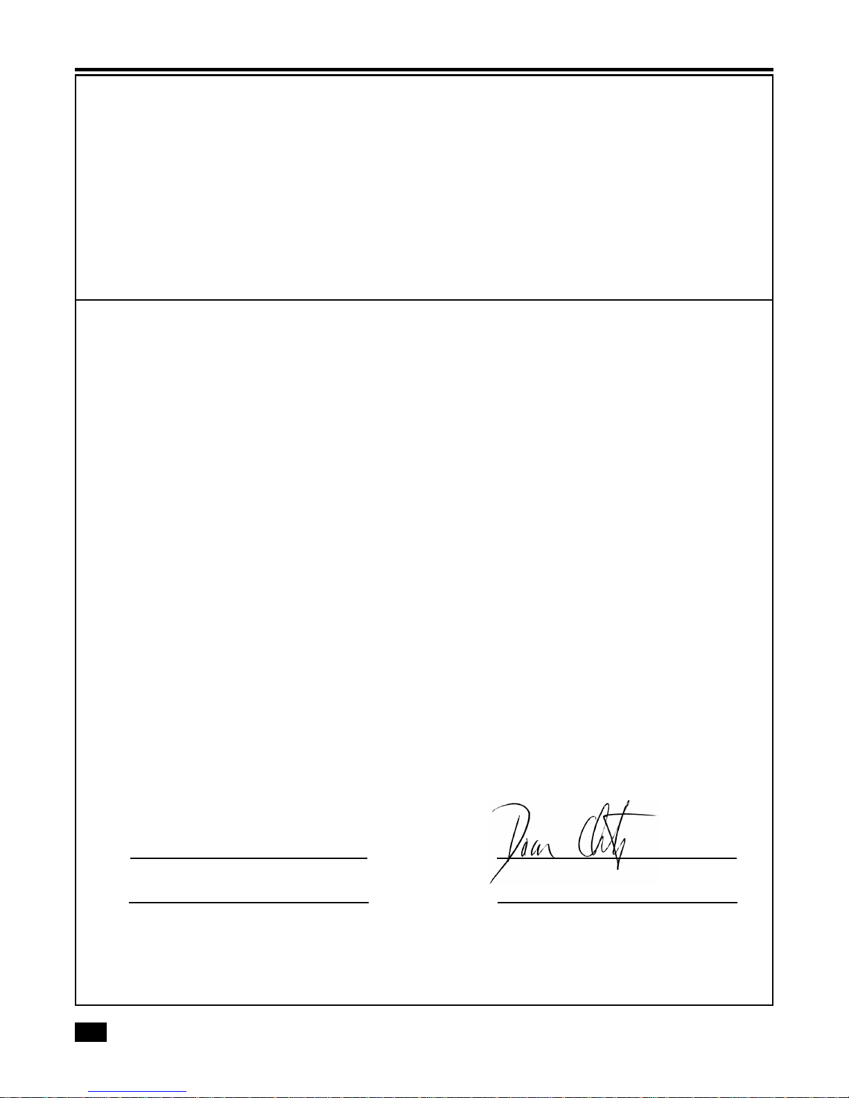
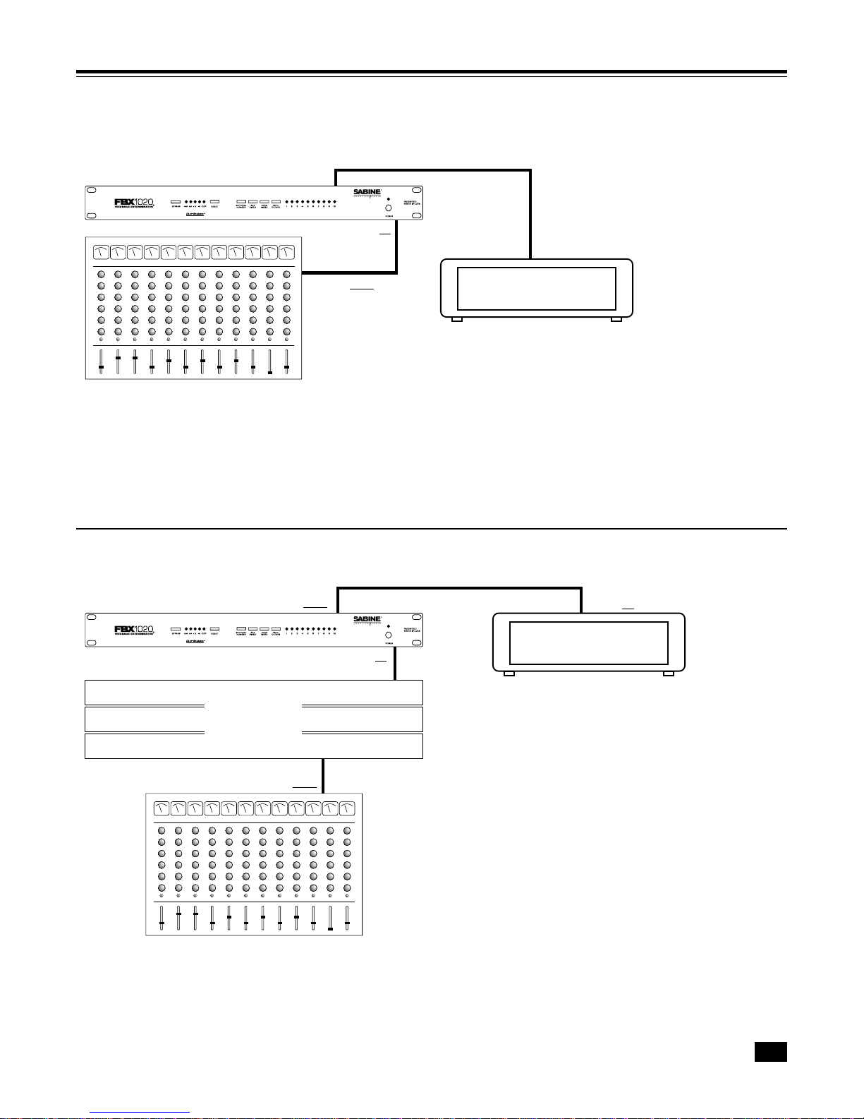
1.Place the speakers and microphones in the positions
where they will be used during the program. Avoid placing
microphones directly in front of speakers.
2. If you possess any equipment in the signal path with a noise
gate,youMUST DISENGAGE these noisegatespriorto the
setup procedure. You may reengage these noise gates
uponconclusionofyourFBXsetup.(Itisalsorecommended
to disengage compressors in the signal path)
3.Set the master volumes to their lowest positions. Turn on
the mixer, then the FBX (make sure the FBX is in BYPASS
mode, with the red BYPASS LED on), then any other
accessories and finally the power amp. If you are using a
graphic EQ, adjust only for the desired tonal qualities, but
DONOTNOTCHFORFEEDBACK.Adjustthebalancefor
each mixer channel, and set the sound system’s master
volume to minimum.
4.Press RESET until all LEDs stop flashing.
5.You may set the total number of filters you want to activate
(factorydefaultis10filters-skipto#6ifdefaultisOKforyour
application)byholdingdowntheSETTOTALNO.buttonfor
4 seconds. The LEDs will blink 4 times and then go out.
Release the SET TOTAL NO. button. The LEDs will begin
to light in sequence. When the LED corresponding to the
desired number of filters lights, press the SET TOTAL NO.
button. You've successfully set the total number of filters.
6.Nowsetthenumberoffixedfiltersyouneed(factorydefault
is7 fixedand 3dynamic -skip to#7 ifdefault isOK foryour
application). DepresstheSETFIXEDbuttonfor4seconds.
The total number of enabled filters set in step 5 will blink
4 times and go out. Release the SET FIXED button, and
the LEDs will begin to light in sequence. When the LED
corresponding to the desired number of fixed filters lights,
press the SET FIXED button. You've successfully set the
number of fixed filters.
7.PressBYPASStoputtheFBXinactivemode(redLEDoff).
8.Slowly raise the sound system’s master volume until
feedback occurs. The FBX will quickly remove the feed-
back.ThefirstFILTERLEDwillthen blink to indicateafilter
has been set. Repeat this procedure until all of the FIXED
FILTERSand one oftheDYNAMIC FILTERS areset.(The
Clip Level mode LED will go off.)
9.Now lower the master volume slightly so that the system
is not on the verge of another feedback point. This is the
maximumvolumelevelthattheFBXwill be able to provide.
Higher levels will cause uncontrollable feedback.
10. You're ready to go. ClipGuard™will automatically match
the input level to the best internal dynamic range.
How To Use The FBX-1020 Features

8
UsingtheLOCK FIXED feature
In very few situations the FBX may mistake music for feedback
and drive the fixed filters deeper than necessary, such as in a
church with a pipe organ, or during a performance with a great
deal of intentional sustained electric guitar feedback. You can
prevent the fixed filters from deepening beyond their preset
depth by pressing the LOCK FIXED button on the front panel
after setup. The LOCK FIXED LED will light to indicate that the
FBX is in LOCK FIXED mode. The fixed filters stay locked until
you press the LOCK FIXED button again.
Selecting filter width
If you're using the FBX for a music application, the standard 1/
10-octave Constant Q filter is usually preferable. However, in
spoken word applications, such as lectures or teleconferenc-
ing, we recommend using the wider 1/5-octave filter for more
robust feedback control. You may enable the 1/5-octave filters
by pressing the "FIFTH OCTAVE" button, and the built-in LED
will light. Only filters set after pressing the button in will be 1/
5-octave. Press the button again to set subsequent filters to
standard 1/10-octave filters. You can mix filter widths in the
same channel (see "IMPORTANT TIP" below).
Important Operating Considerations
Memory
The FBX stores the positions and depths of the filters in
nonvolatile internal memory when the unit is turned off or
during a power failure. The unit will return all filters to their
previous frequencies and depths when it is turned back on.
BypassMode
TheFBX has atrue power-off bypass.The signal isunaffected
in BYPASS MODE even if the unit is turned off. Please note
thatif acombinationofBALANCED andUNBALANCED
inputs and outputs is used, the signal may be discon-
nectedinBYPASSMODE.
Resettingthefilters
The user must reset the FBX if the microphones or speakers
aremovedsignificantly.Toresettheunit,placethePAsystem’s
master volume to minimum and then press the RESET button
untiltheLEDsflashabout 4 seconds —andtheFILTERLEDs
stop flashing. Then follow the system initialization procedure
explained previously.
TURBOModeSetup
The FBX-1020 incorporates TURBO mode setup, which is
indicated by a flashing red “CLIP”LED. This lightning-quick
setup feature cuts the time for FBX filter initialization to just a
few seconds, and it reduces the volume level of the feedback
during setup. The 1020 is set in TURBO mode at the
factory and automatically engages every time you
press RESET (resetting filters). The 1020 automati-
cally returns to normal program mode when the first
dynamic filter is set or when you press the front panel
LOCKFIXEDbutton. ALLFILTERLEDSWILLCYCLETO
INDICATETHEFBXIS ABOUTTO EXITTURBOMODE.
WARNING: TURBOModewillcause distortion in your
audio program — it is for setup only. Youmustfollowthe
setup procedure outlined in the previous section, and do not
play program during TURBO setup mode. Otherwise the 1020
will clip, and filters may be set improperly. (Clip level is set to
the lowest level so the feedback clips quickly; therefore, your
program will also be clipped in TURBO mode. Be sure a
dynamic filter is set, and if one isn’t, press the LOCK FIXED
button before your program begins.) You’ll know the 1020
isinTURBOmodeifthe red CLIP LED flashes when no
other signal level LEDs are lit.
Defeating Turbo Mode
You can manually override TURBO mode if necessary: Press
LOCK FIXED (the LOCK FIXED light will turn on), then press
it again. (LOCK FIXED light will go out).
Mobilevs. StationaryMicrophones
Onesignificant advantageoffered by the Sabine familyof FBX
feedback eliminator products is their ability to adapt to chang-
ing acoustical relationships involving sound system compo-
nents and various user applications. One major source of
potential feedback problems arises in situations with wire-
less microphones, when the user of the wireless mic is
movingaround thestage/auditorium. As a microphone moves
in a sound space, with varying degrees of proximity to the
speakers and varying acoustic responses, feedback frequen-
cies may shift. In such a situation, feedback-free mobility may
be more important a concern than maximum system gain.
One method of setting FBX filters with mobile microphones is
to turn a microphone on and walk around to the various
possible microphone locations. At the same time, raise the
system gain and set the FBX filters one at a time.
In some situations, raising the number of dynamic filters
(versus fixed FBX filters) may allow a second layer of defense
against new feedback from new locations. However, in many
mobile microphone set ups, fixed FBX filters will protect
against feedback across the range of microphone mobility.

9
FREQUENTLY ASKED QUESTIONS
Q. Can I place the FBX in the mixer’s EQ loop?
A. Yes.
Q. Can I place the unit in the mixer effects loop?
A. Avoid this configuration if possible. You can configure the
system this way
only
if each effects send of each mixer
channel is set so that all of the signal is routed completely
through the effects loop. You cannot mix dry signal with
effects signal and still control feedback.
Q. ThesignalinputLEDsdonotlight.Theunitwillnotcatch
feedback. Why?
A. The unit is not in the signal path. Check the connections.
Be sure that the program is interrupted when the input is
disconnected from the back of the unit.
Q. CanImixbalancedandunbalancedinputsandoutputs?
A. Yes. An unbalanced input and balanced output are com-
patible. However,abalanced inputandunbalancedoutput
mayresult ina 6 dBloss ofdynamic range, and the bypass
function may not operate correctly.
Q. WhydoesoneoftheFILTERACTIVITYLEDsblink?
A. The last filter to be automatically updated blinks. During
normal operation, the blinking will move from filter to filter
as they are reset. This gives the user a visual confirmation
thatthe unit isresponding to newfeedback and isfunction-
ing properly.
Q. Sometimesduringtheinitialsetup,thefirstfilterLEDwill
blinkbeforeanyfeedbackhasbeenintroducedintothe
system. Why?
A. The FBX will set a filter if the system has a hum. Check for
bad grounds. Try resetting the filters.
Q. Why does the FBX cause a noticeable hum?
A. Ithums if themain power voltagedrops significantly below
10%of thespecified voltage. Checkthe A/C power mains.
Q. Why does my system sound thin and muffled?
A. PlacetheFBXinBYPASSMODE.Ifthesystemstillsounds
thin, your problem is probably with improper use of a
graphicEQ. Ifthe problem isreallythe FBX, reinitializethe
system.
Q. Why does my program sound clipped and distorted?
A. Make sure the FBX's TURBO mode has turned off before
your program begins. Check the signal level ladder. If the
red CLIP LED flashes when no other signal level LEDs are
on, the FBX-1020 is still in TURBO mode. TURBO mode
turns off automatically after the first dynamic filter is set, or
you can turn it off manually by pressing the LOCK FIXED
button.
Q. Why won't the rest of the fixed filters set after I press
LOCKFIXEDtoturnoffTURBOmode?
A. If you press LOCK FIXED to turn off TURBO mode before
all the fixed filters are set, and you want to use the rest of
thefixedfilters,pressLOCKFIXEDagain
before
adynamic
filter sets. Once a dynamic filter sets, you will not be able
to use the rest of the fixed filters unless you reset the unit
and start initialization again.
INDEX
Symbols
1/10 Octave Filter 3, 4, 6, 8
1/3 Octave Filter 3
1/5 Octave Filter 4, 6, 8
A
Adaptive Clip Level 6
B
Balanced/Unbalanced IN/OUT 4, 7, 8
Bypass 4, 7, 8
C
ClipGuard 4, 6, 7
D
Dynamic Filter 4, 7
F
Filter LEDs 4, 6, 8
Fixed Filter 4, 6, 7
Fuse 4, 10, 11
L
Lock Fixed 4, 6, 7, 8
M
Master Volume (System) 7, 8
Microphone 3, 7, 8
Music Application (for FBX) 8
P
Pipe Organs & FBX 8
R
Reset 6, 7, 8
Reset (dual function) 4
S
Send & Return 7
Set Fixed 4, 7
Set Total Number of Filters 6, 7
Spoken Word Application (for FBX) 8
T
Turbo Mode 4, 6, 7, 8
V
Voltage 4, 11
W
Wireless Microphones 8

10
FBX-1020 ENGINEERING SPECIFICATIONS
(SPECIFICATIONSSUBJECTTOCHANGEWITHOUTNOTICE)
FILTERS
10 independent digital notch filters, controlled automatically from 40
Hz to 20 KHz.
Filter width: user-controllable, either 1/10 or 1/5 oct., Constant Q 1
Resolution: 1/50th Octave
Time required to find and eliminate feedback: 0.4 seconds,
typical @ 1KHz
Total number of combined filters active: user selectable, from
1-10
Number of dynamic vs. fixed filters: user selectable
LASTCONFIGURATIONSTOREDINMEMORY
INPUT/OUTPUT2
Input/Output Maximum Signal Levels: Balanced +27dBV peak,
unbalanced +21 dBV peak
Output Drive: Unit will perform as specified driving a load >600
Ohms
Input Impedance: Balanced or unbalanced >10K Ohms, PIN 2 high
Output Impedance: Balanced or unbalanced 10 Ohms nominal, PIN
2 high
Bypass: True power off bypass
Headroom: +23dB peak @ 4dBV nominal input, balanced
I/O Connectors: XLR-3 and 1/4" TRS
PERFORMANCE3
Spectral Variation: < .25 dB, 20Hz to 20 KHz
SNR: >100 dB, typical, "A" weighted
NOTES
1Below approximately 200 Hz the feedback filters become slightly
wider to increase the feedback and rumble capture speed at these
low frequencies.
2Note: Inputs may be balanced or unbalanced. For maximum output
capability, outputs must be balanced (XLR or TRS). If either side of
an output is grounded, the peak output and dynamic range will be
reduced by 6 dB.
3Tests performed using an Audio Precision System One model 322
or equal.
THD: <0.02% @ 23 dBV sine wave at 1 KHz
Dynamic Range: >110 dB with ClipGuard™automatic clip level
control active
POWERINPUT
Factory configured to either 115 VAC or 230 VAC. 50/60 Hz, 12
Watt input.
FUSEREPLACEMENT
To reduce the risk of fire, replace only with 5x20 mm, .315 A, 250 V,
fast-acting fuse.
DIMENSIONS
1-U rack mount; 19 x 1.75 x 8.0 ins. nominal (rack mountable); 48.3 x
4.5 x 20.3 cm nominal (rack mountable)
WEIGHT
7.0 lbs. (3.3 kg) nominal
OPTIONS
Input/output transformer option
All FBX Feedback Exterminators conform to all Year 2000 (Y2K)
standards.

11
Warning!Thisequipmentmustbeearthed.
Caution!Riskofelectricshock.Donotopen.
Caution!Shockhazard.Donotremovecovers.Nouserserviceableparts
inside.Referservicingtoqualifiedservicepersonnel.
Warning! To reduce the risk of fire or electric shock, do not expose this
producttorainormoisture.
Attention!Cetappareildoitêtrereliéàlaterre.
Attention!Risquedechocélectrique;nepasouvrir.
Attention!Risquedechoc;nepasoterlescapots.Aucunepièceaccessible
àl'intérieur.S'addresseràuntechnicienqualifié.
Attention!Pourréduirelerisqued'incendieoudechocélectrique,nepas
laisserl'appareilsouslaplouieouàl'humidité.
Achtung!DiesesGerätmussschutzgeerdetsein.
Achtung!GefareineselektrischenStormschlags.Gehausenichtöffnen.
Achtung!Gefareineselektrischen Stormschlags.Gehäusenichtöffnen.
KeineconBenutzerzubedienendenTeileimGeräteinneren.
ÜberlassenSiedasGerätzuServicezweckennurgeschultemFachpersonal.
UmBrandgefaroderdasRisikoeineselektrischenSchlagsauszuschließen,
dasGerätvorNässeundFeuchtigkeitschützen.
Advertencia!Esteequipodebeestarconectadoatierra.
Precaución!Reisgodedescargaeléctrica.Noabrir.
Precaución!Riesgodedescargaeléctrica.Nodesmontarlastapas.Piezas
interioresnoreparablesporelusuario.Reparablesóloporpersonalcualificado.
Advertencia!Parareducirelriesgodeincendioodedescargaeléctricano
expongaesteproductoalalluviaohumedad.
FCC Statement:
ThisdevicecomplieswithPart15,ClassB,oftheFCCRules. Operationis
subjecttothefollowingconditions:(1)Thisdevicemaynotcauseharmful
interference;and(2)Thisdevice must accept any interference received,
including interference that may cause undesired operation.
Warning:
Changesormodificationstothisunitnotexpresslyapprovedbytheparty
responsibleforcompliancecouldvoidthe user's authority to operate the
equipment.
NOTE:Thisequipmenthasbeentestedandfoundtocomplywiththelimits
foraClassBdigitaldevice,pursuanttoPart15oftheFCCRules. Theselimits
aredesignedtoprovidereasonableprotectionagainstharmfulinterference
inaresidentialinstallation. Thisequipmentgenerates,uses,andcanradiate
radiofrequencyenergyand,ifnotinstalledandusedinaccordancewiththe
instructions,maycauseharmfulinterferencetoradiocommunications. How-
ever, there is no guarantee that interference will not occur in a particular
installation. Ifthisequipmentdoescauseharmfulinterferencetoradioor
televisionreception,whichcanbedeterminedbyturningtheequipmentoff
andon,theuserisencouragedtotrytocorrecttheinterferencebyoneor
moreofthefollowingmeasures:
•Reorient or relocate the receiving antenna.
•Increase the separation between the equipment and receiver.
•Connect the equipment into an outlet on a circuit different from that
to which the receiver is connected.
•Consult the dealer or an experienced radio TV technician for help.
Canadian Compliance Statement
This digital apparatus does not exceed the Class B limits for radio noise
emissionsfromdigitalapparatussetoutintheRadioInterferenceRegula-
tionsoftheCanadianDepartmentofCommunications.
Le present appareil numerique n'emet pas de bruits radioelectriques
depassantleslimitesapplicablesauxappareilsnumeriquesdelaclassB
prescritesdansleReglementsurlebrouillageradioelectriqueedicteparle
ministeredesCommunicationsduCanada.
CAUTIONS & WARNINGS
1. Read allsafety andoperating instructionsbefore usingthisproduct.
2. All safety and operating instructions should be retained for future
reference.
3. Obey all cautions in the operating instructions and on the unit.
4. All operating instructions should be followed.
5. Use only shielded audio and data cables.
6. This productshouldnot beusedin the presenceof moisture orrain,
or near any water, i.e., a bathtub, sink, swimming pool, wet
basement, etc.
7. This product should be located so that its position does not
interfere with proper ventilation. Do not use in direct sunlight. Do
notplace flat againstawall or ina built-in enclosurethatwill impede
the flow of cooling air.
8. This product should not be placed near a source of heat such as
a stove or radiator.
9. Connect only to a power supply of the type marked on the unit
adjacent to the power entry module.
10. Never break off the ground pin on the power supply cord.
11. Power supply cords should always be handled carefully. Never
walkorplaceequipmentonpowersupplycords. Periodicallycheck
cords for cuts or signs of stress, especially at the plug and the point
where the cord exits the unit.
12. The power supply cord should be unplugged when the unit is to be
unused for long periods of time.
13. Care should be taken so that objects do not fall and liquids are not
spilled into the unit through the ventilation holes or any other
openings.
14. This unit should be checked by a qualified service technician if:
A. The power supply cord or plug has been damaged.
B. Anything has fallen or been spilled into the unit.
C. The unit does not operate correctly.
D. The unit has been dropped or the enclosure damaged.
15. The user should not attempt to service this equipment. All
service work should be done by a qualified service technician.
OSHA 2201; 1995 revised.
The FBX-1020PissuppliedwithoneofthefollowingACpowercords:
Japan 100VAC
U.S./NorthAmerica 120VAC
ContinentalEurope 230VAC
UnitedKingdom 240VAC
Australia 240VAC
Caution!
Replacethefusewithafuseofexactlythesameratingspecifiedonthe
rearoftheproduct.
TheunitisdesignedtooperatefromstandardACpower. Pleasebe
surethepowerinyourareaiscompatiblewiththepowerrequirements
markedontherearoftheunit.Usingthewronginputvoltagemaycause
permanentdamagetotheunitandwillvoidthewarranty.
Warning!
Japanese EMI Compliance Statement

12
Sabine, Inc.
13301 Highway 441
Alachua, Florida 32615-8544
Phone: (904) 418-2000
Fax: (904) 418-2001
©2000 Sabine, Inc.
LIMITED WARRANTY
CAUTION FBXandFBXFeedback Exterminator are registered trademarks
of Sabine, Inc., and are the brand names of its line of automatic
feedback controllers. Covered by U.S. Patent No. 5,245,665,
AustralianPatent No.653,736,Canadian PatentNo.2,066,624-2,
GermanPatent No. 69118486.0, and U.K. Patent No. 0486679.
Otherpatentspending.
REAL-QandREAL-Q2areprotectedbyU.S.PatentNo.5,506,910.
Otherpatentspending.
Graphi-Q,POWER-Q,REAL-Q, andREAL-Q2aretrademarks of
Sabine,Inc.
Copyright 2000. All rights reserved.
THIS LIMITED WARRANTY VALID ONLY WHEN PURCHASEDAND REGISTERED IN THE
UNITED STATES OR CANADA. ALL EXPORTED PRODUCTS ARE SUBJECT TO WAR-
RANTYAND SERVICESTO BE SPECIFIED AND PROVIDED BY THEAUTHORIZED DIS-
TRIBUTOR FOR EACH COUNTRY.
Cesclausesdegarantienesontvaiablesqu’auxEtats-UnisetauCanada.Danstouslesautrespays,
lesclausesdegarantie etdemaintenancesontfixees par ledistributeurnationaletassuree parlui
selonla legislation envigueur.
DieseGarantieistnurindenUSAandKanadagultig.AlleExport-ProduktesindderGarantieunddem
ServicedesImporteursdesjewelligenLandes untervorfen.
Estagarantia esvalida solamentecuandoel productoes compradoen E.U.continentaleso en
Canada.Todoslosproductosqueseancompradosenelextranjero, estansujetos alasgarantiasy
servicioquecada distribuidor autorizadodetermineyotrezca enlosdiferentespaises.
ONE-YEAR LIMITED WARRANTY/REMEDY
SABINE,INC.(“SABINE”)warrantsthisproducttobefreefromdefectsinmaterial and workmanship
foraperiodofone(1) year fromdateofpurchasePROVIDED,however,thatthislimited warrantyis
extendedonlytotheoriginalretail purchaser andissubjecttotheconditions,exclusionsandlimita-
tionshereinaftersetforth:
CONDITIONS, EXCLUSIONS AND LIMITATIONS OF LIMITED WARRANTIES
Theselimitedwarranties shall bevoidandof no effectif:
a.Thefirst purchaseofthe product isforthe purposeofresale;or
b.The original retailpurchase is notmade from anAUTHORIZED SABINE DEALER;or
c.Theproduct hasbeendamagedby accidentorunreasonableuse, neglect,improperserviceor
maintenance,orothercauses notarisingoutofdefects inmaterialorworkmanship;or
d.Theserialnumberaffixed totheproductisaltered,defaced orremoved;or
e.Thepowersupplygroundingpinisremovedorotherwisedefeated.Intheeventofadefect inmaterial
and/orworkmanship coveredbythis limitedwarranty,Sabine willrepairthedefect inmaterial or
workmanshiporreplacetheproduct,atSabine’soption;andprovided,however, that,inanycase,all
costsofshipping,ifnecessary,arepaidbyyou,the purchaser.
THE WARRANTY REGISTRATION CARD (or ONLINE REGISTRATION FORM) SHOULD
BE ACCURATELYCOMPLETED,MAILED TOAND RECEIVED BYSABINEWITHIN FOUR-
TEEN (14) DAYS FROM THE DATE OF YOUR PURCHASE .
Inordertoobtainservice under thesewarranties,youmust:
a.BringthedefectiveitemtoanyAuthorizedSABINEDEALERandpresenttherewiththeORIGINAL
PROOFOFPURCHASE suppliedtoyou bytheAUTHORIZEDSABINE DEALERinconnection
withyourpurchasefromhimofthisproduct. IftheDEALERisunabletoprovidethenecessarywarranty
service,youwillbedirectedtothenearestotherSABINEAUTHORIZEDDEALERwhichcan provide
suchservice. OR
b.Shipthedefectiveitem,prepaid, to:
SABINE,INC.
13301HIGHWAY441
ALACHUA,FL32615-8544
Includetherewithacomplete,detaileddescriptionof the problem,togetherwithalegiblecopyofthe
originalPROOFOF PURCHASEandacomplete returnaddress.Upon Sabine’sreceiptofthese
items:
Ifthedefectisremedialunderthelimitedwarrantiesandtheothertermsandconditionsexpressedhave
beencompliedwith,Sabinewillprovidethenecessarywarrantyservicetorepairorreplacetheproduct
andwillreturn it,FREIGHTCOLLECT,to you,thepurchaser.
Sabine’sliabilitytothepurchaserfordamagesfromanycausewhatsoeverandregardlessoftheform
ofaction,including negligence,islimitedto theactualdamagesup tothegreater of $500.00oran
amountequaltothepurchasepriceoftheproductthatcausedthedamageorthatis the subjectofor
isdirectly relatedtothe causeofaction. Such purchasepricewill bethatin effectfor the specific
productwhenthecauseofactionarose.Thislimitation ofliability will notapplytoclaimsforpersonal
injuryordamageto realpropertyortangiblepersonal property allegedlycausedbySabine’snegli-
gence.Sabine doesnot assume liabilityfor personalinjury orproperty damage arisingout ofor
causedbya non-Sabinealterationor attachment,nordoesSabine assumeanyresponsibility for
damagetointerconnectednon-Sabine equipmentthatmayresultfromthe normalfunctioningand
maintenanceoftheSabineequipment.
UNDERNO CIRCUMSTANCESWILLSABINEBE LIABLEFORANYLOSTPROFITS,LOST
SAVINGS, ANY INCIDENTAL DAMAGES OR ANY CONSEQUENTIAL DAMAGESARISING
OUT OF THE USE OR INABILITY TO USE THE PRODUCT, EVEN IF SABINE HAS BEEN
ADVISEDOF THE POSSIBILITYOF SUCHDAMAGES.
THESE LIMITED WARRANTIESAREINLIEU OFANYANDALL WARRANTIES,EXPRESS
OR IMPLIED, INCLUDING BUT NOT LIMITED TO, THE IMPLIED WARRANTIES OF MER-
CHANTABILITYANDFITNESSFORAPARTICULARUSE;PROVIDED, HOWEVER,THATIF
THE OTHER TERMS AND CONDITIONS NECESSARY TO THE EXISTENCE OF THE EX-
PRESSLIMITEDWARRANTIES,ASHEREINABOVESTATED,HAVEBEENCOMPLIEDWITH,
IMPLIED WARRANTIES ARE NOT DISCLAIMED DURING THE APPLICABLE ONE-YEAR
PERIOD FROM DATE OF PURCHASE OF THIS PRODUCT.
SOMESTATES DONOTALLOWLIMITATION ONHOW LONGANIMPLIED WARRANTY
LASTS,ORTHEEXCLUSIONOR LIMITATIONOFINCIDENTALOR CONSEQUENTIALDAM-
AGES,SOTHEABOVELIMITATIONSOREXCLUSIONS MAYNOTAPPLYTOYOU. THESE
LIMITEDWARRANTIESGIVEYOUSPECIFIC LEGALRIGHTS,AND YOU MAYALSO HAVE
OTHERRIGHTS WHICHMAYVARYFROMSTATETOSTATE.
THESELIMITEDWARRANTIESARETHEONLYEXPRESSWARRANTIESONTHISPROD-
UCT,AND NOOTHERSTATEMENT,REPRESENTATION,WARRANTYORAGREEMENTBY
ANYPERSONSHALLBEVALIDOR BINDING UPONSABINE.
Intheeventofany modificationordisclaimerofexpressor impliedwarranties,oranylimitation
ofremedies, contained hereinconflictswith applicablelaw,then suchmodification,disclaimer or
limitation,asthecasemaybe,shallbedeemedtobemodifiedtotheextentnecessarytocomplywith
suchlaw.
Yourremediesforbreachofthesewarrantiesarelimitedtothoseremediesprovidedherein,and
Sabinegivesthislimitedwarranty only withrespecttoequipmentpurchasedin the UnitedStatesof
America.
INSTRUCTIONS-WARRANTY REGISTRATION CARD
Mailthe completedWARRANTYREGISTRATIONCARD to:
SABINE,INC.
13301HIGHWAY441
ALACHUA,FL32615-8544
OR,registeronlineatwww.SabinePro.com
NOTE:Keep thePROOF OFPURCHASE. In the eventwarranty serviceis requiredduringthe
warrantyperiod,youwillneedthisdocument.TherewillbenoidentificationcardissuedbySabine,Inc.
IMPORTANCE OF WARRANTY REGISTRATION CARDSAND NOTIFICATION OFCHANGES
OF ADDRESS
Shouldnotificationbecomenecessaryforanyconditionthatmayrequirecorrection,theREGISTRA-
TIONCARD,orinformationsubmittedusingtheONLINEREGISTRATIONFORM,willhelpensure
thatyouarecontactedandproperlynotified.
Noticeofaddresschanges-Ifyoumove fromtheaddressshownontheWARRANTYREGISTRA-
TIONCARDorONLINEREGISTRATIONFORM,youshouldnotifySabineofthechangeofaddress
soastofacilitateyourreceiptofanybulletinsorotherformsofnotificationwhichmaybecomeneces-
saryinconnectionwith any conditionthatmayrequiredisseminationof informationorcorrection.
You may contactSabinedirectlyby telephoning (904)418-2000.
Pleasehave theSabine product nameand serial numberavailable when communicating
withSabine Customer Service.
EXPOSURETOEXTREMELYHIGH NOISELEVELSMAYCAUSEAPERMANENT HEAR-
INGLOSS. INDIVIDUALSVARYCONSIDERABLYINSUSCEPTIBILITYTONOISEINDUCED
HEARINGLOSS,BUTNEARLYEVERYONEWILLLOSESOME HEARINGIFEXPOSEDTO
SUFFICIENTLYINTENSE NOISEFORASUFFICIENTTIME. THEU.S. GOVERNMENT’S
OCCUPATIONALSAFETYAND HEALTHADMINISTRATION (OSHA)HASSPECIFIEDTHE
FOLLOWINGPERMISSIBLENOISELEVELEXPOSURES:
DURATION/DAYINHOURS SOUND LEVELINdBA, SLOWRESPONSE
890
692
495
397
2 100
1-1/2 102
1 105
1/2 110
1/4or less 115
ACCORDING TO OSHA, ANY EXPOSURE IN EXCESS OF THE ABOVE PERMISSIBLE
LIMITSCOULDRESULTINHEARINGLOSS. EARPLUGSORPROTECTORSINTHEEAR
CANALS OR OVER THE EARS MUST BE WORN WHEN OPERATING THIS DEVICE IN
ORDERTOPREVENT A PERMANENTHEARINGLOSS,IF EXPOSUREISINEXCESS OF
THELIMITSAS SETFORTHABOVE. TOENSUREAGAINSTPOTENTIALLYDANGEROUS
EXPOSURE TO HIGH SOUND PRESSURE LEVELS, ITIS RECOMMENDED THATALL
PERSONSEXPOSEDTOEQUIPMENTCAPABLEOF PRODUCINGHIGHSOUND PRES-
SURE LEVELS SUCH AS THIS DEVICE BE PROTECTED BY HEARING PROTECTORS
WHILETHIS UNITIS INOPERATION.
FBX-1020-OpGd-v2.P65
11.05.00 -hto
MADEIN USA www.Sabine.com
Table of contents
Other SABINE Stereo Equalizer manuals