Digital-Ally DTM-600 User manual

860-00323-00 Rev E pg.1
DTM-600
Installation Guide

860-00323-00 Rev E pg.2
Contents
1.Overview…………………………. ...............................................................................................................................................3
2. Wiring Diagram .................................................................................................................................................................4
3. Floor Stand Option............................................................................................................................................................6
3.1. Floor Stand…………………..................................................................................................................................................7
3.2. Temp Sensor Option……...............................................................................................................................................11
3.3. Forehead Temperature Sensor Option........................................................................................................................18
4. Desktop Stand Option…….. .............................................................................................................................................24
5. Wall Mount Option………… ..............................................................................................................................................25
6. Terminal Configuration….. ..............................................................................................................................................27
6.1. Device Startup and Login.....................................................................................................................................27
6.2. OSD Configuration………………………………………………………………………………………………………………………………………….28
6.3. Web Portal Configuration....................................................................................................................................30
7.Contact Information……………...........................................................................................................................................33
860-00323-00 Rev E pg.3
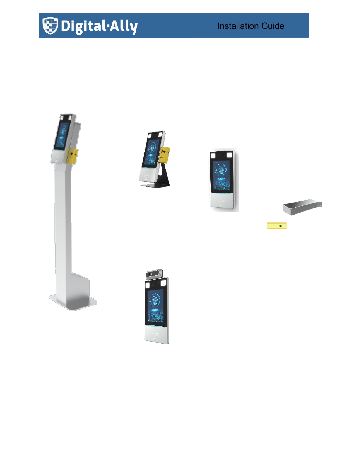
1. Overview
This document provides assembly instructions for the Floor Stand, Desk Stand, Wall Mount, and
Temperature Sensor options for the DTM-600.
The wiring diagram for the terminal and temp sensor apply to each of the three mounting options.
Floor Stand
Option
Desktop
Stand
Option
Wall
Mount
Option
Temp Sensor
Wall Mount
Option
Forehead
Sensor
Option

860-00323-00 Rev E pg.4
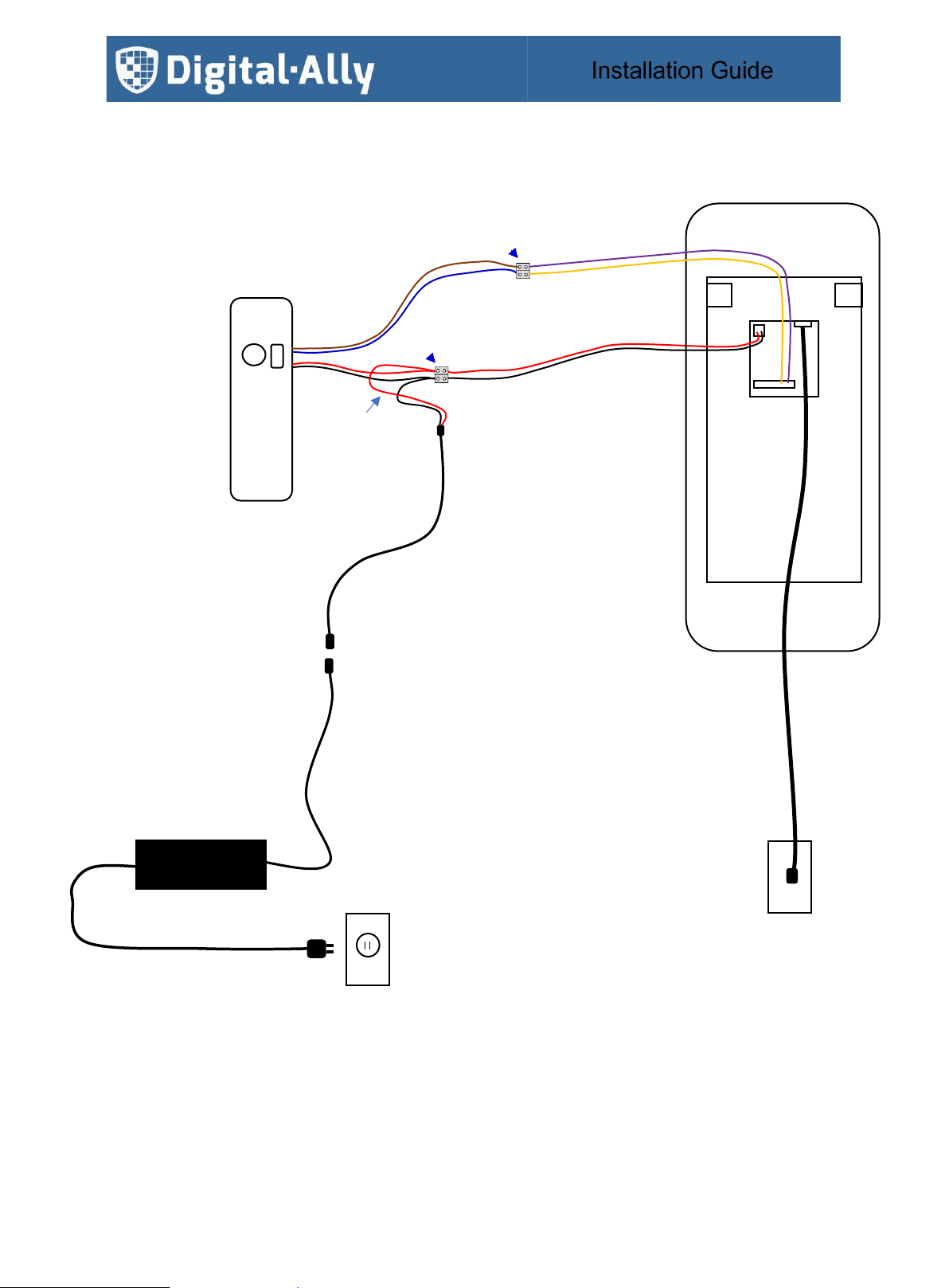
2. Wiring Diagram
Power and Temp Sensor
Wiring Kit
•Crimp Connectors
•Barrier Block
•Power Harness
•Wiring Guide
AC/DC Adapter
Power
Harness
+12vdc
AC Cable
RS485 P
Orange
RS485 N
Purple
RS485 N
Brown
RS485 P
Blue
+12vdc
Gnd
Ethernet
Network
Jack
AC
Outlet
Crimp Connector
Solution
Terminal
Red OR
Black with stripe
Wrist Temp Sensor
OR
Forehead Temp Sensor
Note:
The DTM-600 firmware
can differentiate between
the Wrist Temp Sensor
and Forehead Temp
Sensor. No additional
configuration is required.
860-00323-00 Rev E pg.5
Power
Harness
RS485 P
Orange
RS485 N
Brown
RS485 P
Blue
+12vdc
Gnd
Barrier Block
Solution
RS485 N
Purple
Ethernet
Terminal
Wrist Temp Sensor
OR
Forehead Temp Sensor
Network
Jack
+12vdc
AC Cable
AC
Outlet
AC/DC Adapter
Red OR
Black with stripe
Note:
The DTM-600 firmware
can differentiate between
the Wrist Temp Sensor
and Forehead Temp
Sensor. No additional
configuration is required.

860-00323-00 Rev E pg.6
Ground
3. Floor Stand Option
The mounting plate packaged with the DTM-600 terminal and the mounting bracket packaged with the Temperature
Sensor is mounted to the floor stand. Once the hardware is assembled, reference the wiring diagram to complete the
assembly.
The Floor Stand Base is an option to raise the Floor Stand.
The Extension Plate packaged with the Floor Stand is an option to raise the mounting height of the Terminal.
Floor Stand
Temp Sensor
Bracket Options
Temp Sensor
Mounting
Terminal
Mounting
Floor Stand
Covers
Final Assembly
Floor Stand
Base Option
Extension Plate
Option
Extension Plate Cover
placed over plate

860-00323-00 Rev E pg.7
3.1. Floor Stand
Remove the floor stand from the packaging.
For ease of assembly, place the floor stand on the floor or table face down.
Remove the terminal back plate by removing the 2 screws.
Remove the adapter back plate from the floor stand by removing the 2 screws.
terminal
back plate
adapter
back plate
base
back plate

860-00323-00 Rev E pg.8
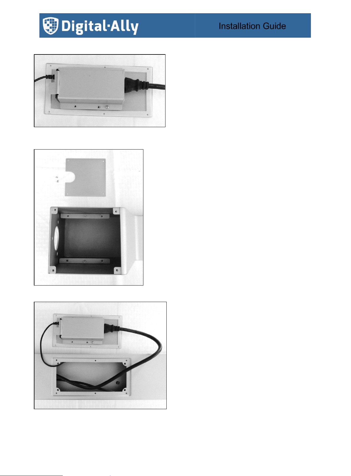
Remove the AC adapter plate from the mid-way back plate by removing the 2 screws.
Note: bending the AC adapter plate as shown will allow the AC adapter to seat flush.
Seat the AC adapter on the adapter plate.
Seat the AC adapter plate atop the mid-way back plate and secure in place with 2 screws.
860-00323-00 Rev E pg.9
Plug the AC cable into the AC adapter.
Remove the back plate at the base of the floor stand.
Feed a network cable (not supplied) into the mid-way access cutout to the top and bottom of the floor stand.
Orient the AC adapter cables as shown below and carefully reseat the mid-way back plate.

860-00323-00 Rev E pg.10
Secure the mid-way back plate in place with 6 screws.
Orient the base plate to align the threaded studs to the floor stand.
Seat and thread the nuts to the threaded studs.
Orient the base back plate to allow the network cable and AC cable through the plate.
Secure the base back plate in place with 4 screws.
Set the floor stand on the side as shown with the temp sensor mounting holes facing up.

860-00323-00 Rev E pg.11
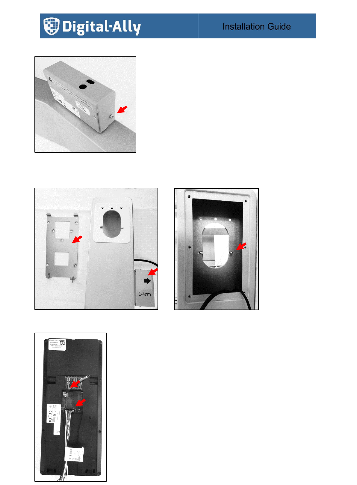
3.2. Temp Sensor Option
Determine what height to mount the temp sensor.
Orient the temp sensor mounting bracket and secure in place using the 2 counter sunk screws supplied
Orient the temp sensor as shown, feeding the harness through the floor stand.
860-00323-00 Rev E pg.12
Seat the temp sensor on the mounting bracket as shown.
Secure the temp sensor to the bracket using the 2 pan head screws supplied.
Apply the temperature sensor label as shown below.
Secure the terminal mounting plate to the floor stand using the 2 bolts and nuts provided.
Plug the power harness and I/O harness into the back of the terminal.
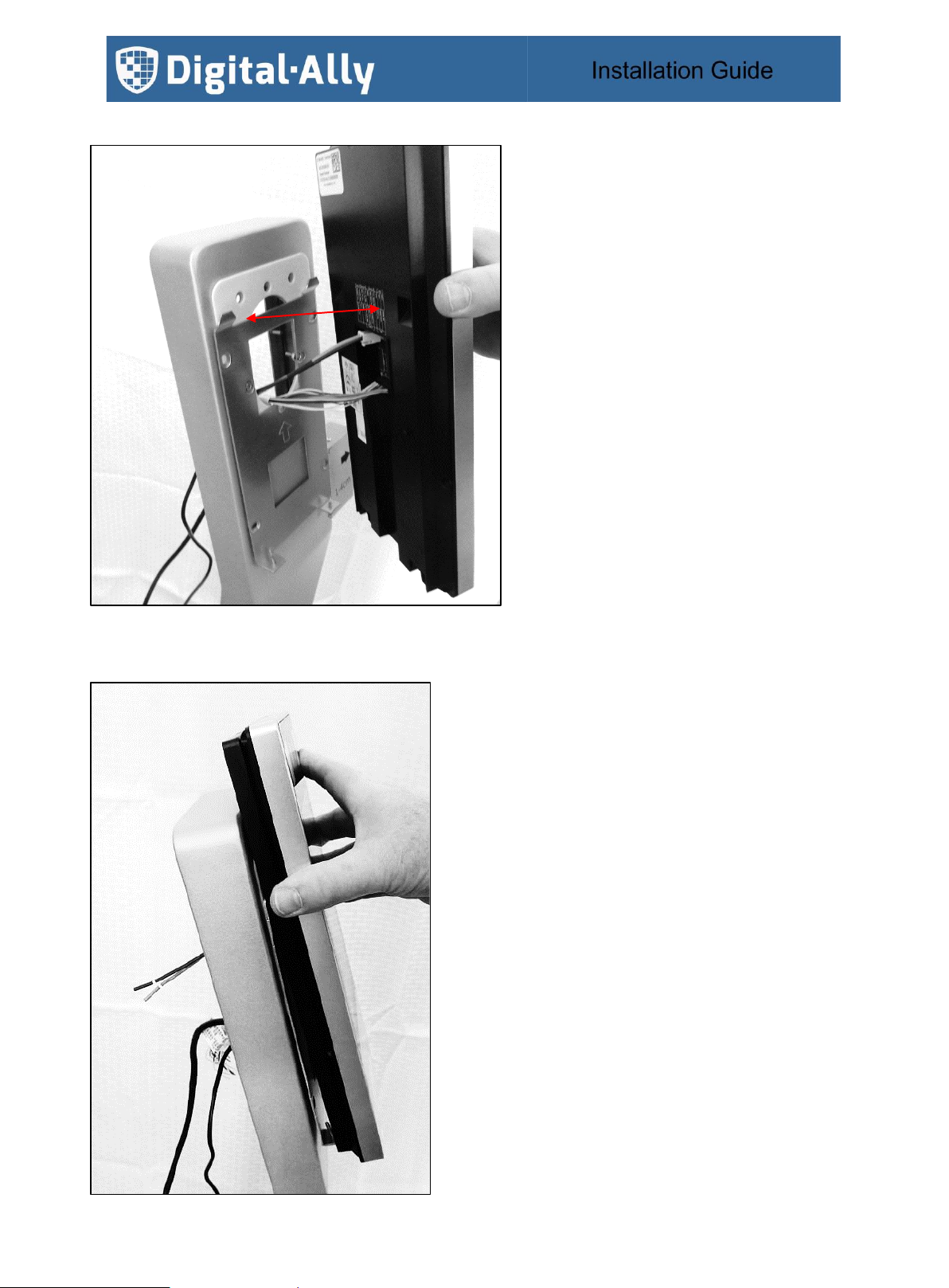
860-00323-00 Rev E pg.13
Feed the power and I/O harness through the mounting plate of the floor stand.
Seat the terminal on the mounting plate.

860-00323-00 Rev E pg.14
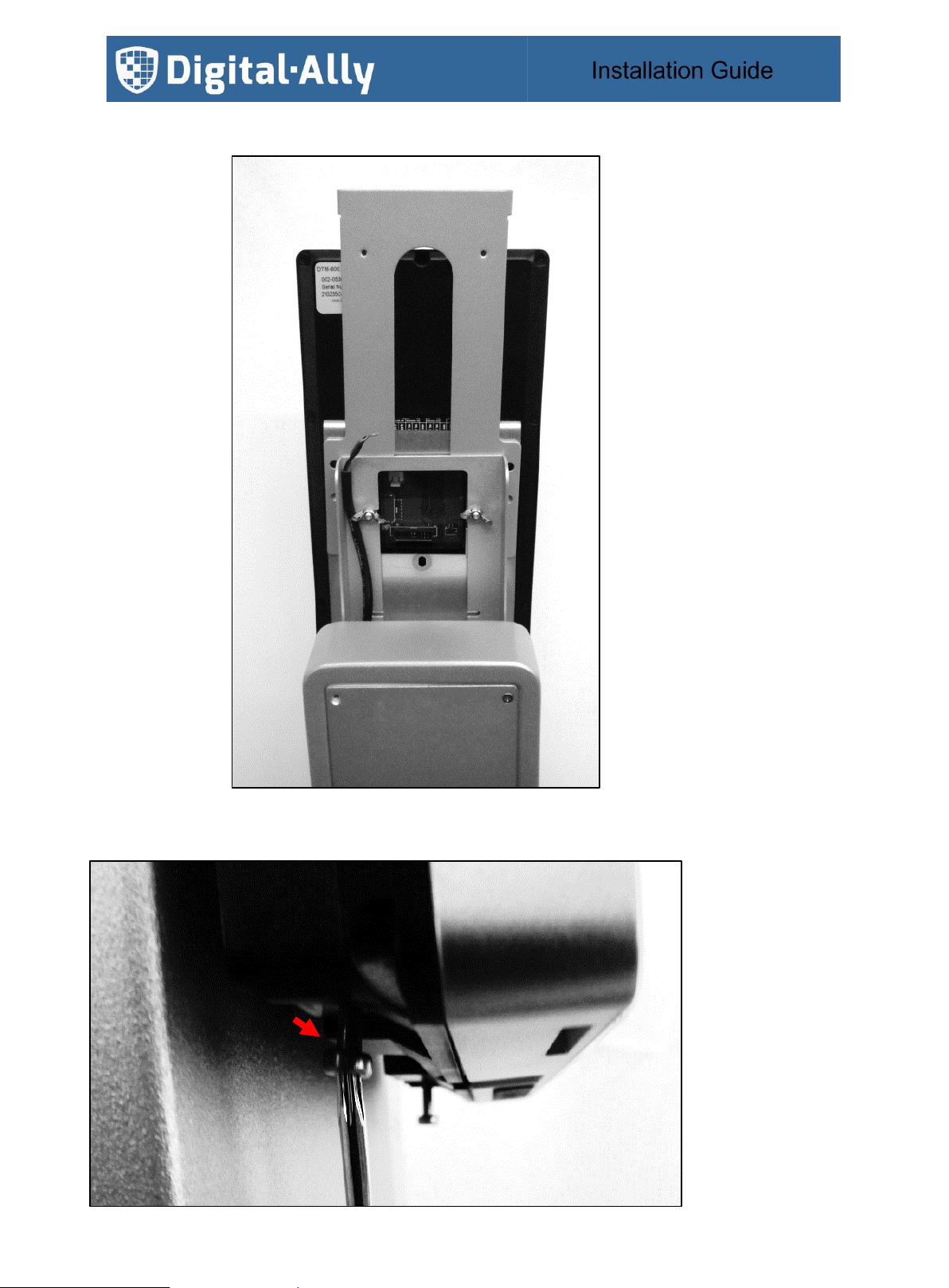
Secure the terminal in place by driving the security screw with the supplied allan key.
Plug the ethernet cable into the terminal.
860-00323-00 Rev E pg.15
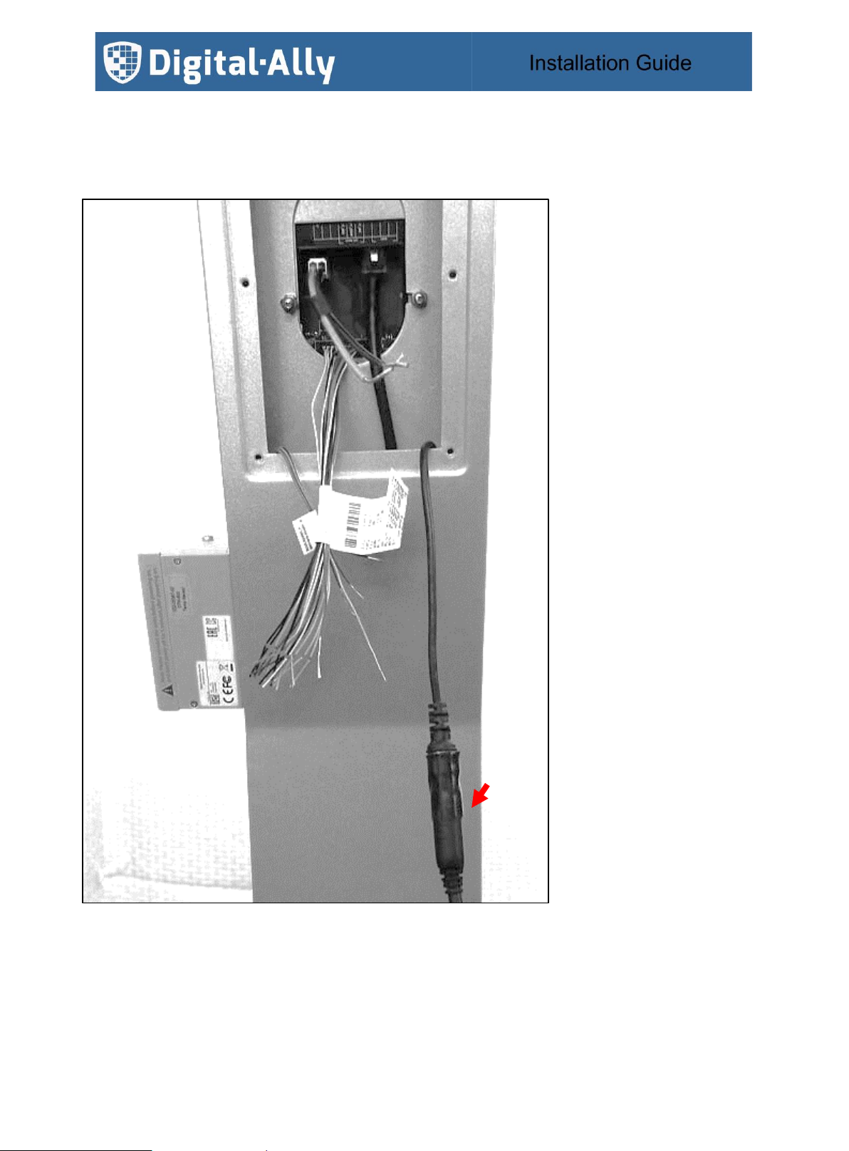
Reference the wiring diagram from Section 2 for power, network, and I/O connectivity.
Connect the power harness included in the wiring kit to the AC adapter and wrap with electrical tape.
860-00323-00 Rev E pg.16
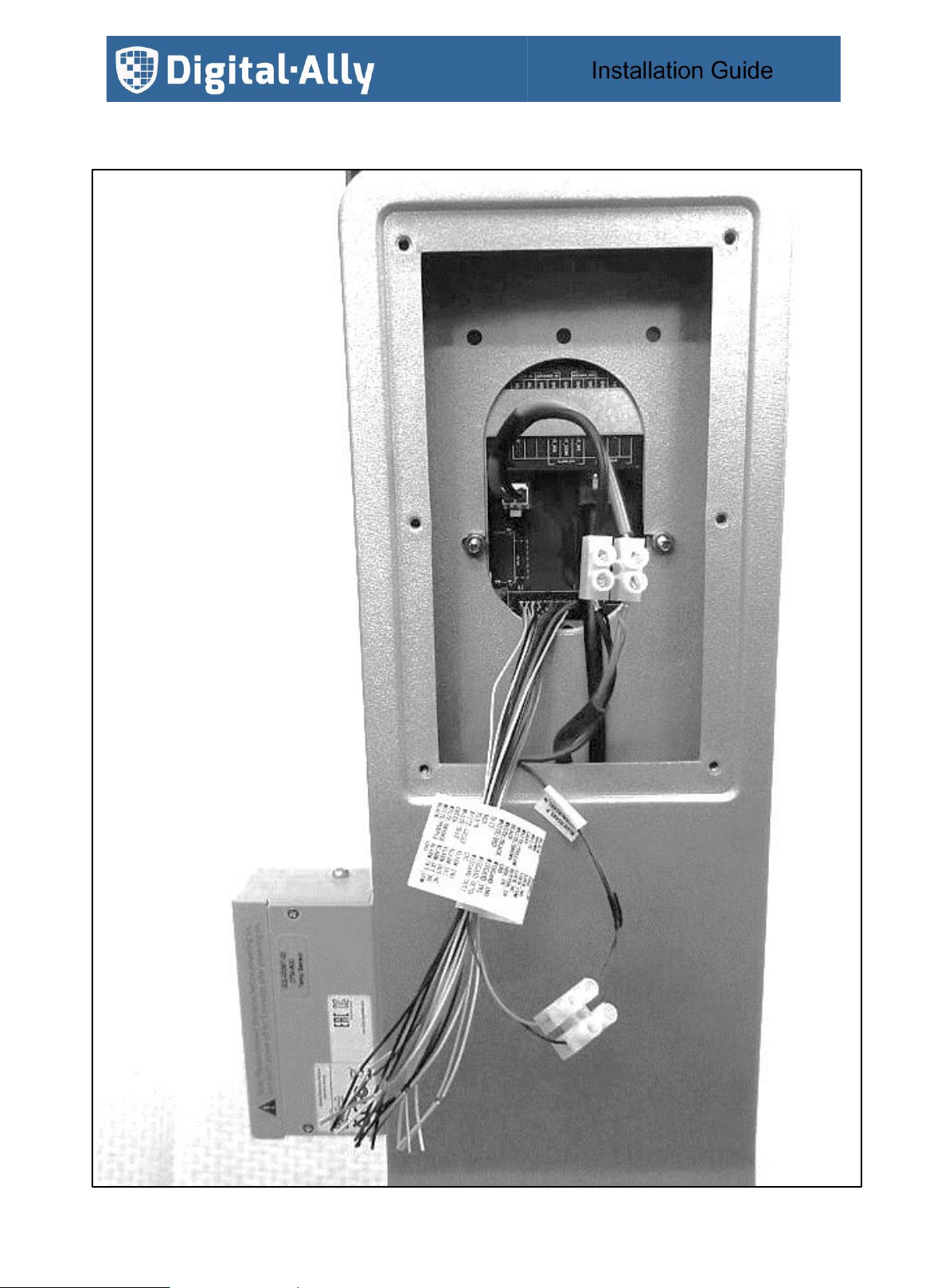
Note: the wiring below makes use of the screw barrier blocks.
RS485
Temp Sensor
Terminal I/O Harness
+12vdc
Temp Sensor Power
Terminal Power Harness
Wiring Kit Power Harness

860-00323-00 Rev E pg.17
Secure the terminal back plate in place with the 6 screws.
Proceed with the Terminal Configuration in Section 6.

860-00323-00 Rev E pg.18
3.3. Forehead Temperature Sensor Option
Use of the extension bracket is recommended to raise the height of the terminal.
Align the extension bracket with the floor stand and secure in place with 2 screws from within the floor stand.
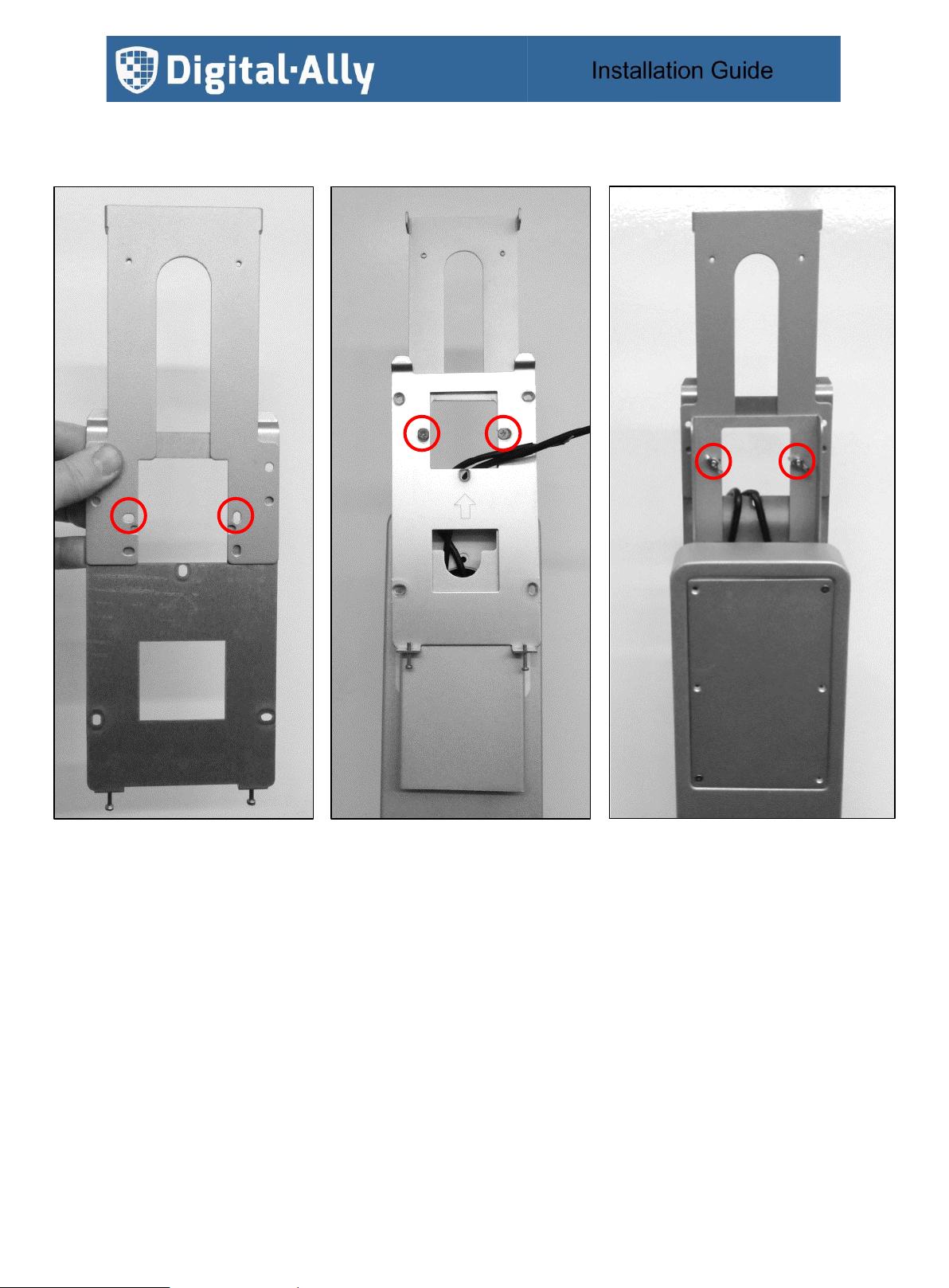
860-00323-00 Rev E pg.19
The Forehead Temperature Sensor mounting bracket is mounted behind the Terminal mounting bracket.
Align the mounting holes of the two brackets as shown below and secure in place with 2 screws and wing nuts.
860-00323-00 Rev E pg.20
Seat the terminal on the mounting plate.
Secure the terminal in place by driving the security screw with the supplied allan key.
Other manuals for DTM-600
1
Table of contents


