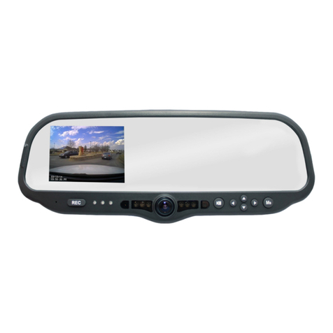
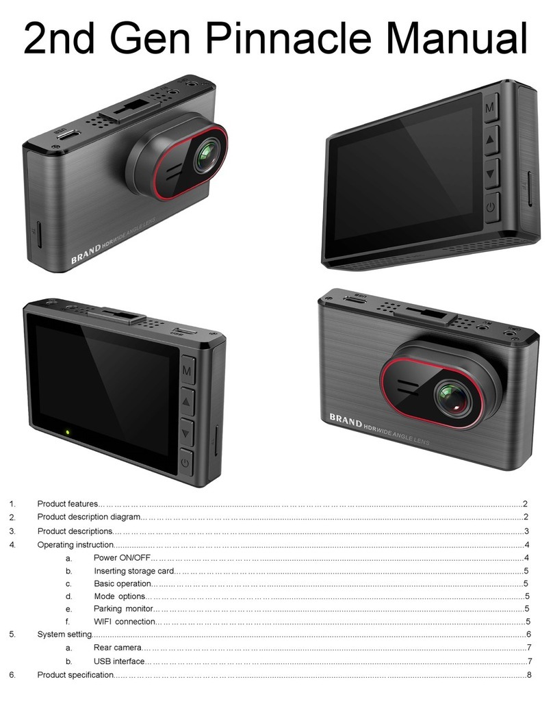
Digital-Ally DVM-800 User manual

Installation Guide
DVM-800
Copyright © 2017, Digital Ally, Inc. All Rights Reserved. This publication may not be repro-
duced, stored in a retrieval system, or transmitted in whole or part in any form or by any
means electronic, mechanical, recording, photocopying, or in any other manner without
the prior written approval of Digital Ally, Inc.
860-00185-00 Rev L

Copyright © 2017 Digital Ally, Inc. i
On behalf of the Digital Ally team, I want to thank you for this order. We appreciate the
trust and condence you have shown us.
We will strive to do everything we can to provide you with the best products, support
and customer service. Please know we have a team of engineers, sales, manufacturing,
customer service, accounting, technicians and support personnel who work to provide
the excellent customer experience and satisfaction you demand and of which is the
cornerstone of our business.
Below are a few comments and suggestions before you get started with the installation
of your Digital Ally DVM-800 system:
• The DVM-800 is designed to be easily installed into virtually any make
or model of vehicle.
• Please check the packing list against the items enclosed to make sure
you have received all the items.
• Pictures of the various components of the system are shown
throughout this guide to assist you.
• Please refer to the DVM-800 Operation Guide for operating
instructions. You can download and print this document by logging in
to the Digital Ally website at http://www.digitalallyinc.com/login.cfm.
• The default passwords to access the DVM can be located on page 4-1
of this document.
• The system diagram is provided on page 2-5, and the wiring
connections chart is provided on page 2-6.
If you need any help, have any questions, or just want to provide some comments,
please feel free to contact us and we will be happy to assist you. We are located in the
Kansas City metro area.
Best regards,
Stanton Ross, CEO
Digital Ally, Inc.
9705 Loiret Blvd
Lenexa, KS 66219
Ph: 800-440-4947 or 913-814-7774
Fax: 913-814-7775
Email: [email protected]
Website: www.digitalallyinc.com
SR/mb

Copyright © 2017 Digital Ally, Inc. ii
Table of Contents
Section 1
Before You Begin........................................................................................................... 1-1
Tools Needed ..................................................................................................................1-1
Cautions and Notes........................................................................................................1-1
Section 2
Parts List and System Diagrams ................................................................................. 2-1
DVM-800 Standard Parts Kit 001-00081-00..................................................................2-1
External Camera Packages............................................................................................2-2
Optional Parts.................................................................................................................2-3
DVM Features Diagram..................................................................................................2-4
System Diagram..............................................................................................................2-5
Wiring Connections Chart .............................................................................................2-6
Section 3
Installation Instructions .............................................................................................. 3-1
Step 1: Factory Mirror Removal ....................................................................................3-1
Screw Mount Rearview Mirror Removal .................................................................................3-1
Wedge (Screwless) Mount Rearview Mirror Removal..........................................................3-1
Cam Lock Rearview Mirror Removal........................................................................................3-1
Step 2: DVM Installation ................................................................................................3-2
Step 3: Interface Box Installation .................................................................................3-3
Interface Box .................................................................................................................................3-3
Mount the IF Box ..........................................................................................................................3-3
DVM to Interface Box Cable Installation.................................................................................3-3
Step 4: Power, Ground, and Input Sensor ...................................................................3-4
Power Cable Installation .............................................................................................................3-4
IF Input Sensor Cable Installation.............................................................................................3-5
Determine the Device Trigger Signal Level ............................................................................3-5
Siren Adapter Interface (optional)............................................................................................3-6
Step 5: Wireless Microphone Installation....................................................................3-6
DWM Wireless Microphone Cable Installation......................................................................3-6
Remote Accessory Out................................................................................................................3-7
Example Relay Wiring Diagrams: ......................................................................................... 3-7
Step 6: External Camera Installation ...........................................................................3-8
Overview .........................................................................................................................................3-8
Option 1: 12XC Camera & Backseat Camera - with 2 Cables ............................................ 3-8
Option 2A and 2B: 12XC Camera & License Plate Camera ................................................ 3-9
Option 3A and 3B: 12XC Camera, Backseat Camera & License Plate Camera.............. 3-10
Option 4: 12XC Camera & Backseat Camera - with Y-Cable............................................ 3-11
Step 3: GPS Module ......................................................................................................3-12
Step 4: Wi-Fi Antenna...................................................................................................3-12
Section 4
Testing the Installation................................................................................................ 4-1
Section 5
Support........................................................................................................................... 5-1
How to Reset the DVM-800 System..............................................................................5-1
Basic Troubleshooting ...................................................................................................5-1
Interface Box Sensor Worksheet..................................................................................5-3
Section 6
Contact Information..................................................................................................... 6-1

Digital Ally, Inc. |Before You Begin 1-1
DVM-800 Installation Guide |860-00185-00 Rev L
Go Back To Table of Contents
This document references the installation of the DVM-800 system, external cameras,
and the cabling harnesses.
Tools Needed
• #2 Phillips head screwdriver
• #20 Torx screwdriver or bit
• 1/8” (4 mm) at-blade screwdriver
• Digital Volt Meter
• Tie wraps
• 16 Gauge Scotchlok or butt connectors
• Wire Crimpers
Cautions and Notes
Please read the following instructions and precautions before installing the DVM-800.
• For assistance, a qualied installation technician or mechanic should
be consulted.
• Do not use excessive force when removing the mirror from the
windshield. The mirror mounting plate may become separated from
the windshield and/or the windshield may break if excessive force
is used. If you are unfamiliar with rearview mirror removal seek
professional assistance.
• Do not route wiring and cabling over sharp metal edges where they
may become damaged or cut.
• To prevent electrical shorts or breakage in the wiring and cabling, do
not allow wiring and cabling to be pinched behind trim pieces, panels,
or other objects.
• Do not run wires or cables in areas where they may become damaged
by heat from the engine or the exhaust system.
• Do not install any DVM components or wiring in the deployment path
of the air bags.
• When installing the cables or making wire connections, it is
recommended you leave a little slack in the cable connections to allow
for service loops and for adjustment of the mirror so the connections
do not get pulled or accidentally disconnected.
• Do not connect any Digital Ally wiring in series with a vehicle charge
guard or battery saver. All system battery connections must be made
to a constant +13.8VDC location within the vehicle.
• Where possible, do not leave excessive cable above the headliner. We
recommend at least 2 feet of distance between our cabling and that of
other systems which may carry a signal for transmit and/or receive.
Section 1
Before You Begin

Digital Ally, Inc. | Parts List and System Diagrams 2-1
DVM-800 Installation Guide |860-00185-00 Rev L
Go Back To Table of Contents
DVM-800 Standard Parts Kit 001-00081-00
External Camera Packages are shown on the next page
Part # Image and Description
006-08265-31 DVM-800, Main Unit
002-05146-00 DVM Mount Assembly
002-05168-00
Accessory Kit: Includes Windshield Mounting Puck,
Lanyard, Mounting Hardware, Security Tamper
Resistant Screw and Key Kit
006-08210-01 IF Box (model IFE-20)
008-01388-00 Cable, Main Power to IF Box 3.1m (10.1ft.)
008-01386-01 Cable, IF Box to DVM 4.6m (15.0ft.)
002-05185-00
DWM-928 System, (900MHz) Includes Wireless
Microphone, Charging Cradle, Mounting Bracket,
and Lapel Microphone. (DWM-865 version available
for countries that require 800MHz)
004-09064-00 Backseat Microphone for DWM-928/865, 20ft.
2.5mm plug
008-0100 Cable, USB 2.0 Type A to Mini-B, 3.3 ft.
008-01455-00 Cable, Wireless Microphone to DVM-800
008-01464-00 Cable, IF Box, Sensor, RJ45
001-00010-20 Wi-Fi Antenna
008-01410-00 GPS Module
363-00087-00 SD card, 32GB
860-00184-00 Quick Reference Guide
Section 2
Parts List and System Diagrams

Digital Ally, Inc. | Parts List and System Diagrams 2-2
DVM-800 Installation Guide |860-00185-00 Rev L
Go Back To Table of Contents
External Camera Packages
Part Number Kit Contents
Option 1
Front 12XC Camera
& Backseat Camera
with 2 Cables
002-05136-12
• 566-00138-00 Front 12XC Camera
• 566-00134-00 Backseat Camera,
w/Smart IR, Reverse Image Switch,
Water Resistant (IP69)
• 008-01390-00 Backup Camera Cable
• 008-01442-00 Cable, 12XC Camera to
DVR
Option 2A
Front 12XC Camera
& License Plate
Camera
002-05136-21
• 566-00138-00 Front 12XC Camera
• 566-00141-00 License Plate Backup
Camera w/adapter cable
• 008-01390-00 Backup Camera Cable
• 008-01442-00 Cable, 12XC Camera to
DVR
Option 2B
Front 12XC Camera
& Mini Backup
Camera
002-05136-22
• 566-00138-00 Front 12XC Camera
• 566-00144-00 Mini Backup Camera
w/adapter cable
• 008-01390-00 Backup Camera Cable
• 008-01442-00 Cable, 12XC Camera to
DVR
Option 3A
Front 12XC Camera,
Backseat Camera
& License Plate
Camera
002-05136-32
• 566-00138-00 Front 12XC Camera
• 566-00141-00 License Plate Backup
Camera w/adapter cable
• 566-00134-00 Backseat Camera,
w/Smart IR, Reverse Image Switch,
Water Resistant (IP69)
• 008-01390-00 Backup Camera Cable
• 008-01443-00 Y-Cable, 12XC Camera
and Backseat Camera to DVR
Option 3B
Front 12XC Camera,
Backseat Camera
& Mini Backup
Camera
002-05136-33
• 566-00138-00 Front 12XC Camera
• 566-00134-00 Backseat Camera,
w/Smart IR, Reverse Image Switch,
Water Resistant (IP69)
• 566-00144-00 Mini Backup Camera
w/adapter cable
• 008-01443-00 Y-Cable, 12XC Camera
and Backseat Camera to DVR
• 008-01390-00 Backup Camera Cable
Option 4
Front 12XC Camera
& Backseat Camera
with Y-Cable
002-05136-42
• 566-00138-00 Front 12XC Camera
• 566-00134-00 Backseat Camera,
w/Smart IR, Reverse Image Switch,
Water Resistant (IP69)
• 008-01443-00 Y-Cable, 12XC Camera
and Backseat Camera to DVR

Digital Ally, Inc. | Parts List and System Diagrams 2-3
DVM-800 Installation Guide |860-00185-00 Rev L
Go Back To Table of Contents
Optional Parts
Part Number Image and Description
008-01382-00
008-01382-01
008-01382-02
008-01382-03
Backup Camera 25ft Extension Cable
Backup Camera 40ft Extension Cable
Backup Camera 60ft Extension Cable
Backup Camera 15ft Extension Cable
025-00018-00
025-00019-00
DWM-928 External 900MHz Antenna.
DWM-865 External 800MHz Antenna.
002-05091-00 Charger, RMT Desktop Charger 120VAC
002-05153-00 Auxiliary 4-Camera Switch Box V3
002-05204-00 SD Card Reader with USB Cable for PC
740-00388-00 Panel Mount Remote Activation Switch
740-00399-00 Footswitch, Maintained (18/2AWG, 6ft, bare
leads)
002-05030-00 Drop Mount Adapter
002-05112-00 Windshield Mount Adapter Kit, Dodge
Charger
006-08267-00 Windshield Mount Adapter Kit, Dodge
Sprinter
006-0030 Visor Mount For external front camera
006-0050 Siren Adapter Interface

Digital Ally, Inc. | Parts List and System Diagrams 2-4
DVM-800 Installation Guide |860-00185-00 Rev L
Go Back To Table of Contents
1
2 3
10
4
11
12
13 14 15 16 417 18
5
6 7 8
9
1 LCD Display: Used for viewing video. LCD is behind the mirror and is not visible when o.
2 Internal Microphone: Records audio from the passenger compartment.
3 Manual Record button: This button is used to Start/Stop a manual event recording.
4LED Status Indicators (Passenger Facing & Road Facing): These visible indicators give the
operator feedback on the operational status of the DVM from inside or outside of the vehicle.
5Infrared Illuminators: Automatically provides Infrared illumination for the Passenger Facing
Camera during low light conditions.
6 Passenger Facing Camera: Records video of the vehicle passenger area.
7Ambient Light Sensor: Senses ambient light to automatically adjust LCD brightness and interior
Infrared Illuminators.
8Menu and Playback Buttons: Used to navigate the DVM menus, play back videos, and log into
the system.
9SD Card: A removable SD card is installed behind the external SD door. The SD card is installed at
a slight angle and positioned with the connector pads as shown above.
10 External Microphone Input: The Digital Wireless Microphone audio cable is connected here.
11 SD Card door: Provides access to the removable SD memory card.
12 USB Port: For data transfer and Wi-Fi download.
13 Camera 1 Port: An external camera can be connected to the DVM with this port.
14 Camera 2 Port: A 2nd external camera is connected to the DVM here.
15 GPS Port: The GPS antenna is connected here.
16 Power Port: Provides power to the DVM. Also used to connect the Interface Box to the DVM.
17 Reset Button: Used to perform a hard reset of the system.
18 Road Facing Camera: Records the view in front of the vehicle.
DVM Features Diagram

Digital Ally, Inc. | Parts List and System Diagrams 2-5
DVM-800 Installation Guide |860-00185-00 Rev L
Go Back To Table of Contents
System Diagram

Digital Ally, Inc. | Parts List and System Diagrams 2-6
DVM-800 Installation Guide |860-00185-00 Rev L
Go Back To Table of Contents
Wiring Connections Chart
Input Signal Color Pin # Description
Main Power Cable (page 3-4)
Battery Red 1
+13.8VDC Unswitched Power. Connect directly to the
engine compartment battery. DO NOT connect any
Digital Ally equipment through a vehicle charge guard
or battery saver.
Ignition 2
+13.8VDC Switched. Powered only when ignition is in
the ACC or On position. Ignition is used to cycle the
system power on and o.
Ground Black 3 Chassis Ground. Secure directly to vehicle frame.
Sensor Input Cable (page 3-5)
Reverse Red 1Connect to reverse gear relay, or reverse light bulb.
Emergency
Lights Orange 2Connect to light bar controller.
+12VDC when emergency lights are activated.
Brakes Blue 3Connect to brake pedal switch or 3rd brake light.
+12VDC when brake is active.
VSS Yellow 4 Connect to Vehicle Speed Sensor pulse signal.
Sensor 5 5Congurable input sensor
Mic Trigger Out Green 6Connect to Green wire of Wireless Microphone Cable
Mic Trigger In Brown 7 Connect to Brown wire of Wireless Microphone Cable
Ground Black 8Chassis Ground
RJ45 RJ45 N/A Connect to “SENS A” RJ45 input of Interface box
DWM Wireless Microphone Cable (page 3-6)
Battery Red 1+13.8VDC Unswitched Power. Connect directly to the
engine compartment battery.
Ground Black 2Connect to Chassis Ground
Mic Trigger Out Green 3 Connect to Green wire of Input Sensor Cable.
Mic Trigger In Brown 4 Connect to Brown wire of Input Sensor Cable.
Remote
Accessory Out Violet 5Connect to auxiliary equipment (optional connection)
RJ45 RJ45 N/A Connect to Wireless Microphone Cradle.
Audio 3.5mm N/A Connect to 3.5mm Ext Mic jack on back of DVM.

Digital Ally, Inc. |Installation Instructions 3-1
DVM-800 Installation Guide |860-00185-00 Rev L
Go Back To Table of Contents
Step 1: Factory Mirror Removal
The current factory rear-view mirror must be removed from the windshield mounting
plate. There are several versions of mirror mounting systems. Below are the most
common methods of rear-view mirror removal. If you are unfamiliar with rearview
mirror removal, seek professional assistance.
Be very careful and do not use excessive force when removing the mirror from
the windshield. The mirror mounting plate may become separated from the
windshield and/or the windshield may break if excessive force is used.
Use one of the following methods that match the mirror mounting conguration of
your vehicle:
Screw Mount Rearview Mirror Removal
1. Using a Philips screwdriver or #20 Torx bit, loosen the screw in the
base of the mirror.
2. After loosening the screw, gently lift upward to slide mirror o of
mirror mount.
Wedge (Screwless) Mount Rearview Mirror Removal
1. Using a small 1/8” (4 mm) at-blade screwdriver, insert the at end into
the opening at the bottom of the mirror mount next to the windshield.
2. Slide the screwdriver into the center of the mirror mount until
resistance is felt.
3. Gently apply a small amount of additional upward force to lift away the
locking spring inside the mount.
4. While still applying upward pressure with the screwdriver, grasp the
mirror bracket and wiggle it from side to side. Lift the mirror up toward
the headliner and o the windshield mount button.
Cam Lock Rearview Mirror Removal
1. With your right hand, grip the mirror
and keep it stabilized.
2. With your left hand, grip the base of the
factory mount where it meets the glass.
3. Apply a small amount of inward
pressure toward the glass and rotate
the base clockwise.
4. The spring loaded factory mount should
release from the windshield puck.
Section 3
Installation Instructions

Digital Ally, Inc. |Installation Instructions 3-2
DVM-800 Installation Guide |860-00185-00 Rev L
Go Back To Table of Contents
Step 2: DVM Installation
1. Install the provided Mirror Mount to the back of the DVM using 3 of the
supplied M4 x 6mm black screws. Using the longer 8mm black screw,
attach one end the Tether Cable to the Mirror Mount and DVM.
2. Slide the new DVM onto the existing windshield mounting plate and
secure your DVM to the vehicle windshield. For some 2011 and later
Dodge vehicles, attach and orient the optional adapter to factory
windshield as shown. Use Loctite™ #03346 glue to secure the adapter
to the factory windshield mount. If needed, attach optional the drop-
down bracket as shown.
3. Use a #20 Torx screw driver to tighten the mounting screw.
4. Adjust the viewing angle for the rearview mirror.
In some vehicles, the position of the manufacturer’s windshield mounting
plate may not allow for proper rearview DVM adjustment for some
individuals, especially when the vehicle is equipped with an overhead console
and/or interior emergency lighting. In these cases, the mounting plate
included with the DVM package must be glued to the windshield in a location
that will allow proper adjustment. Loctite #03346 glue is recommended.
Please follow the instructions on the Loctite package.
5. Securely attach the other end of the Tether Cable to the metal
structure of the vehicle above the DVM using either the supplied self-
drilling screw, or by drilling a hole and using the supplied bolt, nut, and
washer.
The Tether Cable is a safety feature to minimize the chance of personal injury
should the windshield be broken in an accident or if the DVM otherwise
becomes disengaged from the windshield.
6. Remove the protective lm cover from the:
◦Internal Road Facing camera
◦Internal Passenger Facing camera

Digital Ally, Inc. |Installation Instructions 3-3
DVM-800 Installation Guide |860-00185-00 Rev L
Go Back To Table of Contents
Step 3: Interface Box Installation
Interface Box
The IF Box must be securely mounted on a solid area of the
vehicle structure in a moisture free location where it can be
easily accessed for reset or replacement.
Possible mounting locations include:
• Under the dash on the passenger side.
• Behind the kick panel on the passenger side (or driver side).
• Mounted into the transmission tunnel sheet metal below the dash. On
some vehicles this is not advisable due to extreme heat radiated from
the transmission.
• Mounted on the exterior of the center console. Do NOT mount inside
the center console.
• Under the seat on some SUV-type vehicles.
• Behind a panel on the right hand side of the dash (nearest to the door).
• Do not place the IF Box directly on oorboard, or mount it in areas
where it could be exposed to moisture such as air conditioner
condensation, accidental liquid spills, rain, snow, mud, or other
elements that could be tracked into the vehicle.
• Do not place the IF Box in an area that will subject the unit to excessive
heat such as the transmission tunnel or engine rewall.
Mount the IF Box
1. Use the IF Box to DVM Cable as a gauge to estimate an appropriate location for
mounting the IF Box. Secure the IF Box to a location free from moisture.
2. Once a suitable mounting location has been identied for the IF Box, verify that
the shielding strap can be securely connected to the metal surface of the vehicle
chassis. If the shielding strap does not reach a suitable metal surface, reposition the
IF Box appropriately.
3. Secure the unconnected end of the shielding strap to the vehicle chassis.
4. The shielding strap must be connected to a metal surface of the vehicle chassis to
prevent electrical interference. Failure to properly connect the shielding strap may
cause system operation issues.
DVM to Interface Box Cable Installation
1. Plug the IF Box to DVM Cable into the back of the DVM.
2. Leaving slack in the cable at the mirror mounting bracket for
DVM adjustment, begin routing the cable from the DVM under the front edge of the
headliner down the windshield pillar towards the mounting location for the IF Box.
To conceal the cable, it may be necessary to loosen the sun visor mounting bracket
and/or other trim pieces to allow the cable to be tucked in behind the headliner.
3. Do not route wiring and cabling over any sharp metal edges. Avoid running the
cable parallel to other wiring and/or antenna coax from other equipment in the
vehicle. To prevent electrical shorts or breakage in the wiring and cabling, do not
allow wiring and cabling to be pinched behind trim pieces, panels, or other objects.
4. Secure the cable using velcro or standard tie wraps as required.
5. Plug the remaining end of the cable into the IF Box Mirror jack.
IF Box to DVM Cable

Digital Ally, Inc. |Installation Instructions 3-4
DVM-800 Installation Guide |860-00185-00 Rev L
Go Back To Table of Contents
Step 4: Power, Ground, and Input Sensor
Power Cable Installation
1. Plug the connector of the Main Power Cable into the IF Box.
2. Route the cable to a suitable location for electrical
connection.
3. Remove 4 to 5 inches of the outer jacket at the bare end of the power cable.
Separate the braided shield from the individual conductors, attach an electrical
terminal to the end of the braided shield, and attach the terminal to the chassis of
the vehicle.
4. Connect the Red wire of the power cable to the vehicle Positive battery terminal
and the Black wire of this power cable directly to the vehicle’s chassis. It is required
that the power wires be connected to the battery with no obstructions such as a
cuto switch or charge guard system.
5. Connect the White wire to the ignition switch where +13.8VDC is only present when
the vehicle ignition key is in the ON position.
Figure 3-4: Power Connections
Input Color
Power
Connect to +13.8VDC Battery Terminal Red
Ignition
Connect to +13.8VDC Ignition Switch White
Ground
Vehicle Chassis Black
6. Secure the cable and the inline fuse housing using Velcro or standard cable ties
as required. The cable contains a 5 Amp, 250V fuse and a lter to help minimize
unwanted RF noise.
7. Re-connect the cable to the connector on the back of the DVM.
Main Power Cable

Digital Ally, Inc. |Installation Instructions 3-5
DVM-800 Installation Guide |860-00185-00 Rev L
Go Back To Table of Contents
IF Input Sensor Cable Installation
The IF Box provides multi-purpose sensor inputs that allow
external devices to trigger an event record in the mirror.
Common external sensors include; emergency lights, siren,
brake pedal, vehicle speed sensor, reverse gear, covert
foot-switch, or door sensors.
Determine the Device Trigger Signal Level
For the administrator to congure each of the six multi-purpose input sensors, the
signaling from the external device must be found and documented. Determine the
signaling of each external device that will be used and document the signal information
on the Interface Box Sensor Worksheet that has been provided on page 5-3.
1. Position the RJ45 end of the sensor cable near the IF Box RJ45 jack, but
do not plug it into the IF Box yet.
2. Leaving a service loop for connection to the IF Box, begin routing the
non-terminated end of the sensor cable to the desired location in the
vehicle for connection to each of the input sensor devices.
3. Cut o excess cable as required.
4. Use Figure 3-5 below for wiring connections to the sensor cable and
connect the external devices to the appropriate wire of the RJ45 sensor
cable.
5. The Green and Brown wires are reserved for the DWM wireless
microphone system. Connect the wires as shown in below to ensure
microphone activation functions correctly. Use butt splice connectors
to connect the green and brown wires.
6. When all external devices have been connected, plug the RJ45 into the
jack labeled “SENS A” on the IF Box.
Figure 3-5: Input Sensor Connections
Pin Sensor Wire Color
1Reverse
Reverse Gear Sensor Red
2Lights
Connect to +12VDC Light Bar Output Orange
3Brakes
Connect to +12VDC Brake Switch Blue
4
Speed
Connect to VSS Output
(Vehicle Speed Sensor) Yellow
5Sensor #5
Congurable Input
6Mic Trigger Out
Connect to Green wire of DWM harness Green
7Mic Trigger In
Connect to Brown wire of DWM harness Brown
8Ground
Connect to vehicle chassis Black
N/A Sensor In/Out
Connect to “SENS A” input on interface box RJ45
IF Box Sensor Input Cable

Digital Ally, Inc. |Installation Instructions 3-6
DVM-800 Installation Guide |860-00185-00 Rev L
Go Back To Table of Contents
Siren Adapter Interface (optional)
If an acceptable DC output cannot be obtained from the siren controller, the
optional Siren Adapter Interface can be used to connect the siren speaker
to the interface box. Follow the diagram below to install the siren interface.
White
White
Red
Yellow
Siren
Speaker
Output
To DVM-800 HD
IF Box Sensor Input
When using the siren adapter, the input sensor must be congured for a High
to Low, Standard Threshold within the VuVault device conguration.
Step 5: Wireless Microphone Installation
1. Attach the mounting bracket to the back of the
Wireless Microphone Cradle; the assembly can then be
mounted at your preferred location, such as the side
of the center console. Do not mount the cradle in close
proximity to a cup holder or other area which may be
exposed to moisture. Damage caused by a liquid spill
is not covered under warranty.
2. Attach the antenna. If you are using the external In-Car
Microphone, connect it to the DWM Cradle Microphone jack and route
the microphone to your preferred location in the vehicle. The typical
mounting location for the external in-car microphone is in the rear seat
area along the headliner & below the weather strip.
DWM Wireless Microphone Cable Installation
Carefully route the cable to the Ext Mic jack on the back of the DVM. Make the following
connections:
Figure 3-6: Wireless Microphone Cable Connections
Connection Wire Color
Power
Connect to +13.8DVC Battery Terminal Red
Ground
Connect to vehicle chassis Black
Remote Accessory Out
Connect to auxiliary equipment
(optional connect, see next page) Violet
Microphone Trigger Out
Connect to Green wire of IF Sensor Cable Green
Microphone Trigger In
Connect to Brown wire of IF Sensor Cable Brown
Transmit/Receive
Connect to RJ45 input jack on the DWM
Microphone Cradle RJ45
Audio Out
Connect to 3.5mm Ext Mic jack on
the back of the DVM
3.5mm Audio
Plug

Digital Ally, Inc. |Installation Instructions 3-7
DVM-800 Installation Guide |860-00185-00 Rev L
Go Back To Table of Contents
When connecting the 3.5mm Audio Plug to the Ext Mic jack on the back of the DVM, be
sure to leave enough slack in the cable to allow for adjustment of the mirror.
3.5mm Audio
Input Jack
Remote Accessory Out
The Remote Accessory Out button (unmarked) on the top of the DWM Microphone
Transmitter can be congured to activate or deactivate an auxiliary device. Below is a
general outline showing how this can be wired using an interposing relay.
The device, relay, and fuse are optional customer provided items. Be sure to select a
relay which can handle the power requirements of your device.
Example Relay Wiring Diagrams:
1. Activate device when button is momentarily pressed: To activate a
+12VDC device that is normally o by default by pressing the button,
connect it as shown below. When the button is pressed once, the relay will
be energized and the external device will be powered on. When the button
is pressed again, the relay will not be energized and the device will turn o.
2. Deactivate device when button is momentarily pressed: To deactivate a
+12VDC device that is normally on by default by pressing the button,
connect it as shown below. When the button is pressed once, the relay will
be energized and the device be powered o. When the button is pressed
again, the relay will not be energized and the device will be powered on.
Remote Accessory Button
Note: Pressing this button does not
cause a recording to start.

Digital Ally, Inc. |Installation Instructions 3-8
DVM-800 Installation Guide |860-00185-00 Rev L
Go Back To Table of Contents
Step 6: External Camera Installation
Overview
There are 6 External Camera Package options for the DVM-800. Choose the instruction
that matches the camera option you have purchased.
Option 1: 12XC Camera & Backseat Camera - with 2 Cables
1. Attach the visor mount through the visor clip and attach front camera
to the mounting plate as shown below. Connect the 12XC camera cable
(008-01442-00) to the DVM-800 CAM1 input.
2. Determine a mounting location for the backseat camera.
The example below has the camera mounted in
the center of the cage. This gives a wide angle view of
the entire back seat. Secure the camera using the
supplied hardware.
DO NOT install the backseat camera behind
plexiglass (or glass); The infrared lights will reect back
into the camera lens and completely obscure any video.
3. If the camera is to be mounted facing the rear of the
vehicle, adjust the image switch on the back of the
camera to the Reverse position.
4. Attach the backseat camera cable (008-01390-00) to the DVM-800
CAM 2 input. Secure extra cable in the headliner away from any other
existing cabling and/or airbags. Leave slack in the cable as a service
loop and for DVM adjustment; then begin routing the cable to the
backseat area. To conceal the cable it may be necessary to loosen
interior trim and other components within the vehicle.

Digital Ally, Inc. |Installation Instructions 3-9
DVM-800 Installation Guide |860-00185-00 Rev L
Go Back To Table of Contents
Option 2A and 2B: 12XC Camera & License Plate Camera
1. Attach the visor mount through the visor clip and attach front camera
to the mounting plate as shown below. Attach the front camera cable
(008-01442-00) to the DVM-800 CAM 1 input.
2. Determine a mounting location for the backup camera. Secure the
camera using the supplied hardware.
3. Attach the backup camera cable (008-01390-00) to the DVM-800
CAM 2 input. Leave slack in the cable as a service loop and for DVM
adjustment; then begin routing the cable to the rear of the vehicle.
4. Depending on your vehicle you may be able to route the cable down
the side of the headliner to a rear compartment of the vehicle.
Otherwise nd a suitable route on the oorboard of the vehicle.
5. To conceal the cable it may be necessary to loosen interior trim and
other components within the vehicle.
6. The cable connector for the Backup Camera should be routed to a rear
compartment of the vehicle such as the trunk of a car, to a location
within 3 feet of the rear license plate.
Mounting the License Plate Backup Camera (Option 2A)
7. Remove the top two screws holding the rear license plate to the
vehicle.
8. Use the screws to attach the backup camera bracket along the top
edge of the license plate.
Mounting the Mini Backup Camera (Option 2B)
9. Using the supplied self-drilling screws, mount the camera to an
appropriate location on the back of the vehicle where it will not
obscure any part of the license plate.

Digital Ally, Inc. |Installation Instructions 3-10
DVM-800 Installation Guide |860-00185-00 Rev L
Go Back To Table of Contents
Option 3A and 3B: 12XC Camera, Backseat Camera & License Plate Camera
If a backup camera is used, the vehicle’s reverse gear signal will allow the DVM LCD
image to switch to the Licence Plate camera when active. In this conguration, the
front and backseat cameras share the single Y-Cable (008-01443-00) on the CAM 1 port.
The License Plate camera uses the CAM 2 port. You must also connect to the vehicle’s
reverse gear signal. Please consult the “DVM-800 Operation Guide” for assistance with
creating a device conguration le.
1. Attach the visor mount through the visor clip and attach front camera
to the mounting plate as shown below. Attach the camera Y-Cable
(008-01443-00) to the DVM-800 CAM 1 input.
2. Determine a mounting location for the backseat camera. The example
on page 3-8 has the camera mounted in the center of the cage. This
gives a wide angle view of the entire back seat. Secure the camera
using the supplied hardware.
DO NOT install the backseat camera behind plexiglass (or glass); The
infrared lights will reect back into the camera lens and completely obscure
any video.
3. Route the remaining portion of the camera cable to the backseat
camera and connect. Secure extra cable in the headliner away
from any other existing cabling and/or airbags. Leave slack in the cable
as a service loop and for DVM adjustment. To conceal the cable it may
be necessary to loosen interior trim and other components within the
vehicle.
4. Attach the backup camera cable (008-01390-00) to the DVM-800
CAM 2 input. Leave slack in the cable as a service loop and for DVM
adjustment; then begin routing the cable to the rear of the vehicle.
5. Depending on your vehicle you may be able to route the cable down
the side of the headliner to a rear compartment of the vehicle.
Otherwise nd a suitable route on the oorboard of the vehicle.
6. To conceal the cable it may be necessary to loosen interior trim and
other components within the vehicle.
7. The cable connector for the Backup Camera should be routed to a rear
compartment of the vehicle such as the trunk of a car, to a location
within 3 feet of the rear license plate.
Other manuals for DVM-800
2
This manual suits for next models
1
Table of contents
Other Digital-Ally Dashcam manuals
